

Page 1
3B SCIENTIFIC® PHYSICS
U10300 Optical bench, triangular profile, 1 m
U10301 Optical bench, triangular profile, 2 m
U10302 Optical bench, triangular profile, 0.5 m
U10304 Set of supports for the optical bench
U10305 Swivel joint
6/03 ALF
Instruction sheet
®
The optical bench and its accessories are used in experiments with optical components for research and
demonstrations where the highest degree of precision
is required for adjustment of axes and distance measurement. The swivel joint permits experiment configurations where the beam path is deflected.
1. Description, technical data
1.1 Optical benches
1
2
5
4
3
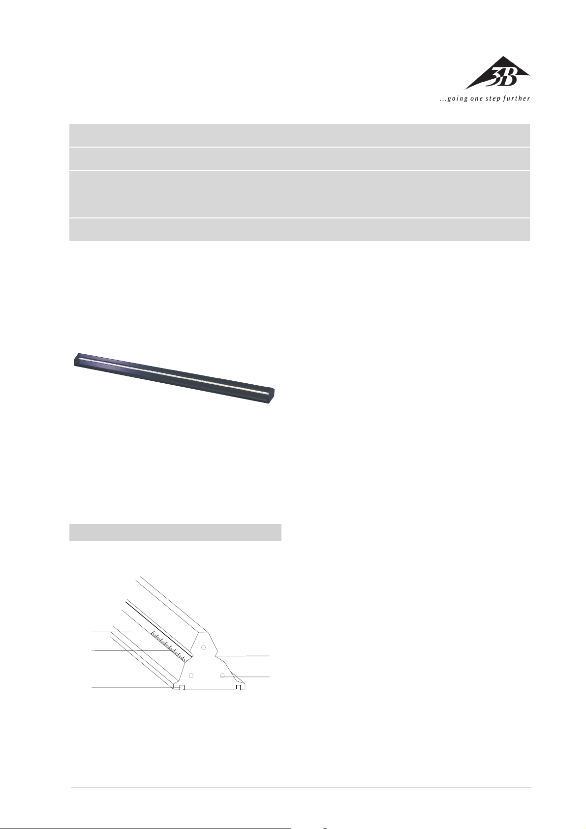
Abb. 1: 1 Rail 2 Scale
3 Groove for mounting 4 Drill hole for attaching the
the rail feet swivel joint
5 Groove for the tightening of the optical rider
The optical bench made of triangular-profile, black
anodised aluminium is tilt-proof, deformation- and
torsion-proof as well as anti-slip. A continuous scale in
cm/mm division is attached to both sides. Two grooves
on the supporting surface are available for optional
mounting on two rail supports or one support and a
single-point support. There are three drill holes at the
front end for fastening the end plate or the swivel joint.
U10300 1 m Weight: approx. 3.5 kg
U10301 2 m Weight: approx. 7 kg
U10302 0.5 m Weight: approx. 1.75 kg
1.2 Set of supports for the optical bench
This set consists of two rail supports and a single-point
support made of black anodised aluminium. It allows
for height adjustment of the optical bench in a fourpoint or three-point support configuration.
Length of the supports: 270 mm
3
Page 2
Rotational angle: ± 90°
Protractor: ±180°
Scale division: 1°
Sleeve height: 60 mm
Span width for shaft: 10 mm up to 14 mm
1
5
2
4
3
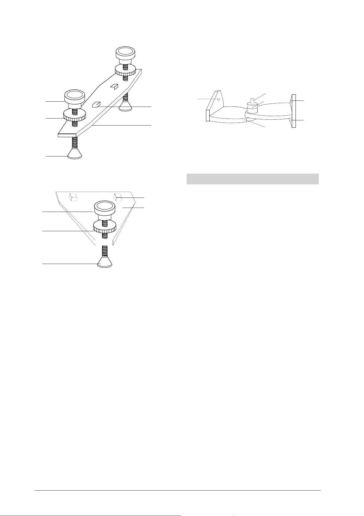
Fig. 2.1 Rail supports
5
1
4
2
3
Fig. 2.2 Single-point support
1 Adjustment screw to adjust the height
2 Grub-screw to secure the height
3 Stand base
4 Rail support
5 Square-socket screw to fasten the rail foot into the groove
1.3 Swivel joint
The swivel joint consists of black anodised aluminium
and can be swivelled around an angle of 90° in both
directions. A protractor has been included to set the
angle. In the rotational axis there is a sleeve to mount
optical components.
1
2
1
1
1
Figure 3
1
Drilled screw holes for fastening to the optical bench
2
Mount for protractor and sleeve
2. Operation
2.1 Assembly of the rail supports
• Insert the square-socket screws into the guide
groove under the profile rail and fasten by tightening them.
• Adjust the height using the adjustment screw.
• Use the grub-screw to secure the settings.
2.2 Assembly of the swivel joint
• Take off the front plate by loosening the three fastening screws.
• Place the swivel joint on the rail and secure it by
tightening the three screws.
• Connect the swivel joint to the second rail in like
fashion.
2.3 Recommended rider and assembly aids
• For the assembly of elements in the optical axis:
Optical rider (U10310 to U10312 and U10315 to
U10317)
Double rider (U10340 to U10342)
• To tilt element out of the optical axis:
Tilting rider (U10330)
• To slide elements perpendicular to the optical
bench axis: sliding rider (U10320)
• To position elements adjacent to the optical axis:
Extension arm (U10331)
2
3B Scientific GmbH • Rudorffweg 8 • 21031 Hamburg • Deutschland • www.3bscientific.com • Technical amendments are possible
4
 Loading...