


3B SCIENTIFIC® PHYSICS |
® |
|
U10010 Ultrasonic Echoscope and Accessories
Operating instructions
6/04 ALF
1
234 5 6
bu
bt
bs
br
bq bp |
bobn bm bl 9 |
1
2
3
4
5
6
7
8
79 bl
bm
8bn bo bp bq br bs bt bu
Start point for time-dependent amplification
Trigger slope (rise time) for time-dependent amplification Width of time-dependent amplification
Threshold for time-dependent amplification Transmitter power
Receiver gain
Power supply
Mains switch
Receiver unit
Probe connection for reflection mode or receiver in transmission mode
Reflection/transmission mode changeover switch Probe connection for transmission mode Transmitter unit
Clocking unit (time-dependent amplifier)
Connector sockets for oscilloscope
Signal output A scan (LF signal)
Signal output (HF signal)
Signal output for trigger signal
Signal output for time-dependent amplifier ramp
Safety instructions
For your own safety and that of the equipment, please read the following instructions thoroughly before using this ultrasonic device and its accessories.
The slits in the device are for ventilation and must not be covered to avoid overheating of the equipment. We recommended that the feet on the device be used.
Ensure that the specified operating voltage and safety measures are observed.
Never try to insert objects through the ventilation slits since this could lead to short circuits or electric shocks. Connect only the ultrasonic transducer supplied by 3B Scientific GmbH to the "PROBE" sockets. Caution: the transmitting transducer may experience voltage pulses as high as 300 V.
Be aware that this is laboratory equipment and not a medical appliance. The ultrasonic sensors are not to be used on people or animals.
|
|
Contents |
|
1. |
Introduction ........................................ |
12 |
|
2. |
Components ......................................... |
12 |
|
2.1. |
U10010 |
Ultrasonic echoscope controls ....... |
12 |
2.2. |
Ultrasonic transducers................................ |
12 |
|
2.2.1. |
U10015 |
1-MHz ultrasonic transducer ......... |
12 |
2.2.2. |
U10017 |
4-MHz ultrasonic transducer ......... |
12 |
2.3. |
Accessories ................................................. |
12 |
|
2.3.1. |
U10027 |
Acrylic block with holes ................. |
12 |
2.3.2. |
U10020 |
Equipment set for longitudinal |
|
|
and transverse waves .................................. |
12 |
|
2.3.3. |
U10022 |
Aluminum block with |
|
|
protractor scale .......................................... |
13 |
|
2.3.4. |
U10023 |
Polyoxymethylene (POM) plate |
|
|
with protractor scale .................................. |
13 |
|
2.3.5. |
U10025 |
Reflection plate ............................. |
13 |
2.3.6. |
U10026 |
Set of three cylinders ..................... |
13 |
2.3.7. |
U10029 |
Heart valve model ......................... |
13 |
2.3.8. L55/1 Model of a single breast |
|
||
|
with benign tumor ..................................... |
13 |
|
All rights are reserved by 3B Scientific GmbH. No part of this operating manual may be reproduced, rewritten, copied or redistributed in any form without the express permission of 3B Scientific GmbH.
3B Scientific GmbH accepts no responsibility for damage caused by incorrect use of the equipment, nor for any repairs or modification made by third parties other than those authorized by 3B Scientific GmbH.
11

3. |
Software .............................................. |
13 |
3.1. |
Program operation ..................................... |
13 |
3.2. |
Menu functions .......................................... |
14 |
4. |
Suggested experiments .......................... |
14 |
4.1. |
Wave nature of ultrasound ......................... |
14 |
4.2.Determining the frequency
of the transducer in use ............................. |
15 |
4.3.Speed of longitudinally propagated
|
sound in test bodies ................................... |
15 |
|
4.4. |
Attenuation of sound in test bodies ........... |
15 |
|
4.5. |
Attenuation of sound in fluids .................... |
16 |
|
4.6. |
Frequency-dependent attenuation ............. |
16 |
|
4.7. |
Time-dependent amplifier ......................... |
17 |
|
4.8 |
Frequency dependence of resolution ......... |
18 |
|
4.9. |
Manually guided B image ........................... |
18 |
|
4.10. Time-motion mode (M mode) ..................... |
18 |
||
4.11. Transmission coefficient and speed |
|
||
|
of transversely propagated sound .............. |
19 |
|
4.12 |
Combination of B image and |
|
|
|
A scan – testing of materials ...................... |
20 |
|
5. |
Technical details .................................. |
20 |
|
5.1 |
U10010 Ultrasonic echoscope controls ....... |
20 |
|
5.2. |
U10015 |
1-MHz ultrasonic transducer ......... |
20 |
5.3. |
U10017 |
4-MHz ultrasonic transducer ......... |
20 |
5.4. |
U10027 |
Acrylic block with holes ................. |
20 |
5.5 |
U10020 |
Equipment set for |
|
|
longitudinal and transverse waves ............. |
20 |
|
5.6 |
U10022 |
Aluminum block with |
|
|
protractor scale .......................................... |
20 |
|
5.7.U10023 Polyoxymethylene (POM) plate
|
with protractor scale .................................. |
20 |
|
5.8. |
U10025 |
Reflection plate ............................. |
20 |
5.9. |
U10026 |
Set of three cylinders ..................... |
20 |
5.10. |
U10029 Heart valve model ......................... |
20 |
|
5.11. L55/1 Model of a single breast with benign |
|
||
|
tumor ......................................................... |
|
20 |
6. |
Bibliography ........................................ |
20 |
|
1. Introduction
Ultrasonic echoscopy (also called sonography) has developed into one of the key procedures for medical examination and materials technology. Although there is a confusingly wide range of ultrasonic devices produced for various applications, all of them rely on the same basic principle of emitting a mechanical wave and recording the reflections in an echogram.
2.Components
2.1.Ultrasonic echoscope controls U10010
The U10010 echoscope is an ultrasonic A-image device with an output for pure pulse echo operation and an extra output and converter for operation with two ultrasonic transducers for transmission measurements. The device is equipped with a parallel interface for connection to transfer data to a PC.
To make the principle behind the device clearer, the individual components, receiver, transmitter and time-
dependent amplifier can be viewed separately. The gain for the amplification of the received signal can be adjusted in 5-dB steps from 0 to 35 dB. The transmitter power can be adjusted in 10-dB steps from 0 to 30 dB. For time-dependent amplification, the start point, the rise time, the threshold and the width can all be continuously adjusted up to a maximum gain of 35 dB.
Also included is the ASH control software for Microsoft Windows. This allows you to measure amplitude and timing differentials. It also supports the simultaneous display of HF signal and amplitude signal so that, unlike with conventional A-image equipment, the wave nature of ultrasound can be demonstrated. An additional chart simultaneously shows the form of and change in the time-dependent amplification. Other software options include: manually guided B-images; time-motion mode; FFT on a selected signal segment; zoom function; changeover between time and resolution depending on the speed of sound, which can also be adjusted; switching between measuring ranges; data export and print capability; automatic mode display (transmission or refection).
2.2.Ultrasonic transducer
2.2.1. Ultrasonic transducer 1 MHz U10015
For examinations at greater depth or examinations involving high power and low depth resolution, 16-mm piezo-ceramic disc in cast metal housing, preset for water propagated sound, one cable with frequencycoded snap-in plug.
2.2.2. Ultrasonic transducer 4 MHz U10017
For examinations requiring maximum depth resolution at shallow depth, 16-mm piezo-ceramic disc in cast metal housing, preset for water propagated sound, 1-m cable with frequency-coded snap-in plug.
2.3.Accessories
2.3.1. Acrylic block with holes U10027
For determining speed of sound and attenuation of an ultrasonic signal in acrylic (polyacrylate), for pinpointing discontinuities, and investigating imaging errors caused by sound shadows or ground echoes, fre- quency-dependent resolution capacity and display of a manual B image. To investigate resolution, both the 1-MHz and the 4-MHz transducers are required. Polished polyacrylate block with drilled holes of various diameter for simulating discontinuities at various distances from the surface of the block.
2.3.2.Equipment set for longitudinal and transverse waves U10020
For investigating the propagation of longitudinal and transverse (shear) waves in solid bodies and determining elastic constants (shear modulus, modulus of elasticity and Poisson number) of these bodies. Also for determining ultrasonic attenuation in fluids by means
12
of time-dependent amplitude measurement with moveable reflector.
Ultrasound is first passed vertically through a body under test placed in a trough filled with water. Only longitudinal waves are propagated through the body. The transmission amplitude of these is recorded. In rotating the body to ever greater angles, the amplitude of the longitudinal waves decreases and transverse waves are increasingly propagated through the body. These appear in the amplitude domain as a second peak.
From the angle where total reflection of the longitudinal waves takes place, the speed of the longitudinal waves can be calculated. The speed of transverse waves can be calculated from the angle where the maximum transmission amplitude for transverse waves occurs. If the body is rotated further, total reflection of the transverse component may also occur depending on the magnitude of the speed of sound in proportion to that in the surrounding fluid.
From the two speeds of sound, the elastic constants (shear modulus, modulus of elasticity and Poisson number) for the body under test can be calculated.
Acrylic (included in the scope of delivery), aluminum and polyoxymethylene (POM) plates are available as test bodies. The speed of transverse waves in acrylic (polyacrylate) is almost exactly the same as in water. In aluminum the speed is greater and in POM it is smaller than in water.
Set consists of sounding trough, acrylic test plate in holder with protractor scale and two transducer holders for 1-MHz or 4-MHz ultrasonic transducers that allow for precise positioning of the transducers on the sounding trough.
2.3.3.Aluminum plate with protractor scale U10022
Accessory for longitudinal and transverse waves equipment set for investigating the propagation of transverse waves in metals and for determining the elastic constants such as shear modulus, modulus of elasticity and Poisson number for aluminum; high quality reflector (large reflection coefficient in water) and therefore easy- to-measure signal amplitudes for attenuation measurements in liquids (e.g. water, cooking oil, glycerine).
2.3.4.Polyoxymethylene (POM) plate in test holder with protractor scale U10023
Accessory for longitudinal and transverse waves equipment set for investigating the propagation of transverse waves in plastic and for determining the elastic constants such as shear modulus, modulus of elasticity and Poisson number for POM.
2.3.5. Reflection plate U10025
Polished acrylic plate for investigating multiple echoes and measuring frequency-dependent attenuation. The 4-MHz transducer is particularly suited for measurements of this kind. Initially an echo image with at least three echoes is recorded and the spectrum of the
individual echoes analyzed. The result is a shifting of the median frequency to lower frequencies since the higher frequency components are more strongly attenuated.
2.3.6. Set of 3 cylinders U10026
Polished polyacrylate cylinders for determining speed of sound and attenuation of ultrasound in acrylic. Measurements can be made using reflection mode or transmission mode.
2.3.7. Heart valve model U10029
Twin chamber with rubber membrane and pressure regulator for demonstrating the action of heart valves using the time-motion method. During the experiment, the membrane chamber produces an image similar to that produced by a valve of a beating heart in an electrocardiogram as used for medical diagnosis.
2.3.8. Model of a single breast with benign tumor
Imitation breast made of silicon with a simulated benign tumor for demonstrating B-image mode.
3.Software
3.1. Program operation
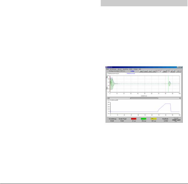
As soon as the program is started, the measuring equipment is immediately activated. The user interface is shown in the illustration above. In the top part of the screen, the A-image signal, the current position of the markers (vertical red and green lines), the frequency of the receiving transducer that is connected and the current mode (reflection/pulse echo or transmission). The markers can be positioned using the mouse (the mouse cursor changes when the markers are to be moved).
The scale for the time axis (time measurement) can be switched to display distance (depth measurement) ["Time"/"Depth" buttons]. An entry for the speed of propagation as required for calculation can be made using the Settings option in the menu (default: 1000 m/s). The UP-DOWN button pairing at the left-hand edge of the screen is for changing the amplitude resolution (top) and shifting the zero-axis (bottom).
13
 Loading...