


N-Doped Germanium on Printed Circuit Board
3B SCIENTIFIC
N-doped germanium on circuit board 1009760
Instruction manual
03/12 ALF
1. Safety instructions
®
PHYSICS
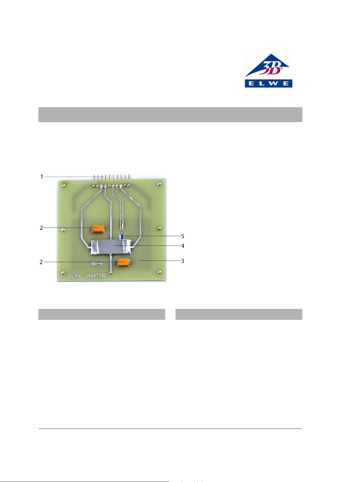
1 Multi-pin plug
2 Spacer
3 Heating element
4 N-doped germanium crystal
5 PT100 thermocouple
2. Description
The germanium crystal is highly breakable:
• Handle the board carefully and do not put any
mechanical stress on it.
The sample circuit board can get very hot when in
operation (170°C) and there is a risk of burns.
• Before dismantling the board from the apparatus,
allow it sufficient time to cool.
Because of its high resistivity, the germanium crystal
will start to heat up as soon as a sample current is put
through it.
• Do not exceed the maximum sample current I =
±33 mA.
• Turn the trimmer for setting the sample current to a
position in the centre.
The circuit board is intended for use with the Hall
effect basic apparatus (1009934) in order to measure
the conductivity and Hall voltage of n-doped
germanium as a function of temperature. In addition,
it is also possible to study how the Hall voltage
depends on an external magnetic field and the sample
current through the crystal.
The circuit board has a multi-pin plug with contacts for
a sample current, the resistive heating element and
the temperature sensor underneath the crystal.
1
3. Contents
1 Circuit board with germanium crystal
1 Test record
1 Instruction manual
4. Technical data
Maximum sample current: ±33 mA
Dimensions of crystal: 20x10x1 mm approx.
Dimensions: 70x70x10 mm approx.
Weight: 30 g approx.
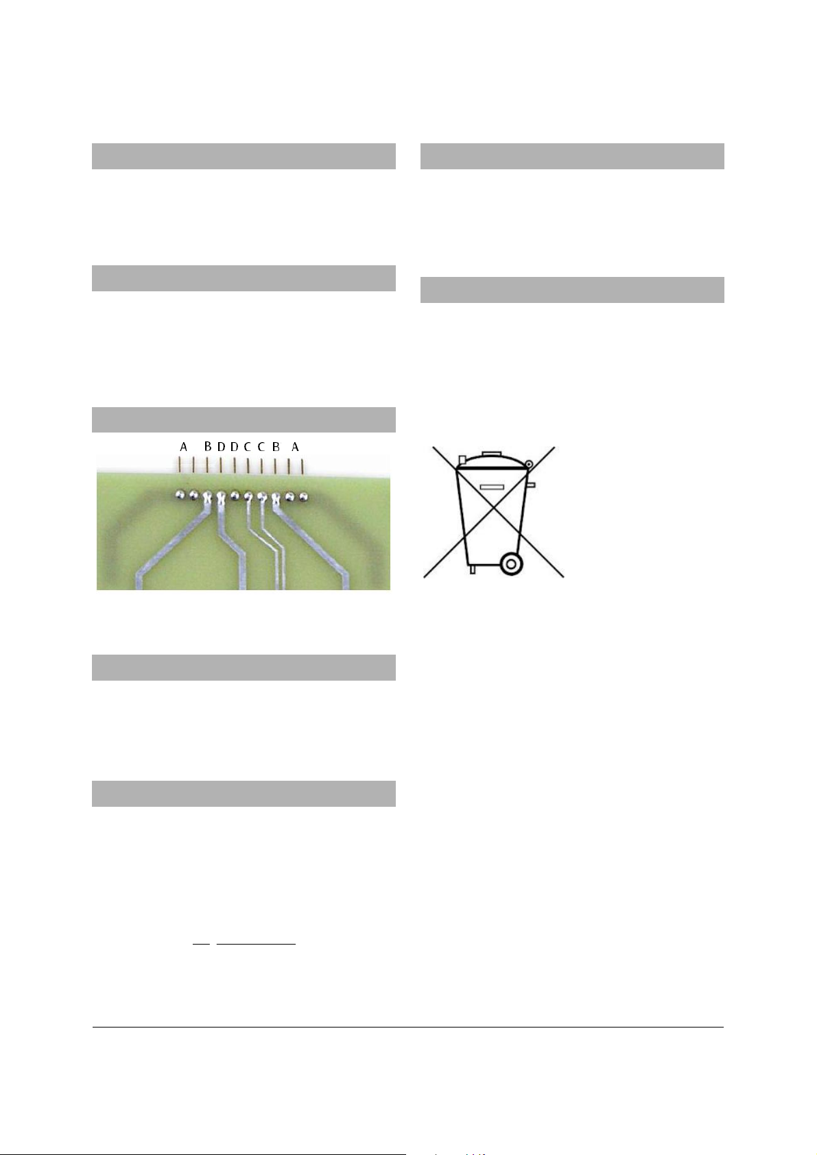
5. Pin assignment
8. Care and maintenance
• Use a soft brush to clean the board. Do not touch
the crystal with your fingers if possible.
• Keep in the original box after the equipment has
been used and has cooled down.
9. Disposal
• If you need to dispose of the circuit board, never
throw it away in normal domestic waste. Local
regulations for the disposal of electrical
equipment will apply.
The packaging is made of environmentally-friendly
materials and can be recycled.
• You can dispose of it at local recycling points.
Fig.1 A Heating element, B Sample current through
germanium crystal, C PT100 thermocouple, D Hall voltage
6. Operation
Installation of the circuit board in the Hall effect
console and the circuit diagram for the experiment are
included in the instruction manual for the Hall effect
equipment itself.
7. Measurement values
Hall voltage U
H
Sample voltage U
(basic apparatus)
(basic apparatus)
Sample current I (basic apparatus)
Sample temperature T
(basic apparatus)
P
Magnetic flux B (with magnetic field sensor)
Derived values:
Conductivity:
I
U
Absolute temperature in Kelvin:
mm 20
⋅=σ
mm 1mm 10
⋅
K 273,15+=PTT
2
 Loading...