


3B SCIENTIFIC® PHYSICS
Free-Fall Tube with 6 Induction Coils U8511200
Instruction sheet
12/09 SP/ALF
1 |
Free-fall tube |
2 |
Coil |
3 |
Connector sockets |
4 |
Plinth with socket |
5 |
Bar magnet |
6 |
Cork mat |
1. Description
The free-fall tube with 6 induction coils is used to illustrate the principles of induced voltages.
The free-fall tube is a plastic tube that is mounted upright on a plinth and has six identical induction coils connected in series with one another. Within the clamp socket of the plinth there is a rubber washer, which prevents the falling body (a bar
magnet) from bouncing back up the tube after the impact.
If the bar magnet is allowed to fall through the tube, a voltage is induced in each of the coils in turn. Since the velocity of the magnet increases with time as it falls, the amplitudes of the voltage peaks also increase as time passes, while their widths decrease. The area under each of the voltage peaks remains constant.
1
By using the 3B NETlogTM unit as an interface or by means of a storage oscilloscope it is possible to display the voltage curve graphically. Two 4 mm sockets are provided for making the connections.
After falling, the magnet is held in the rubber washer and can be retrieved when the plinth is tilted sideways. The cork mat serves to protect the magnet and the table top from damage by the impact.
2. Technical data
Coil width: |
5 mm |
Distance between coils: |
180 mm |
Number of turns: |
13 in each coil |
Overall dimensions: |
130x200x1020 mm3 approx. |
Weight: |
500 g approx. |
3.Assembly
•Set up the tube in the socket of the plinth using gentle pressure.
Bumps, knocks or any lateral forces acting on the tube may damage the instrument.
•Do not subject the tube to any mechanical stress.
|
|
4. Operation |
|
|
|
Also required: |
|
|
1 |
3B NETlogTM |
U11300-230 |
or |
3B NETlogTM |
|
1 |
U11300-115 |
|
1 |
3B NETlabTM |
U11310 |
Experiment leads
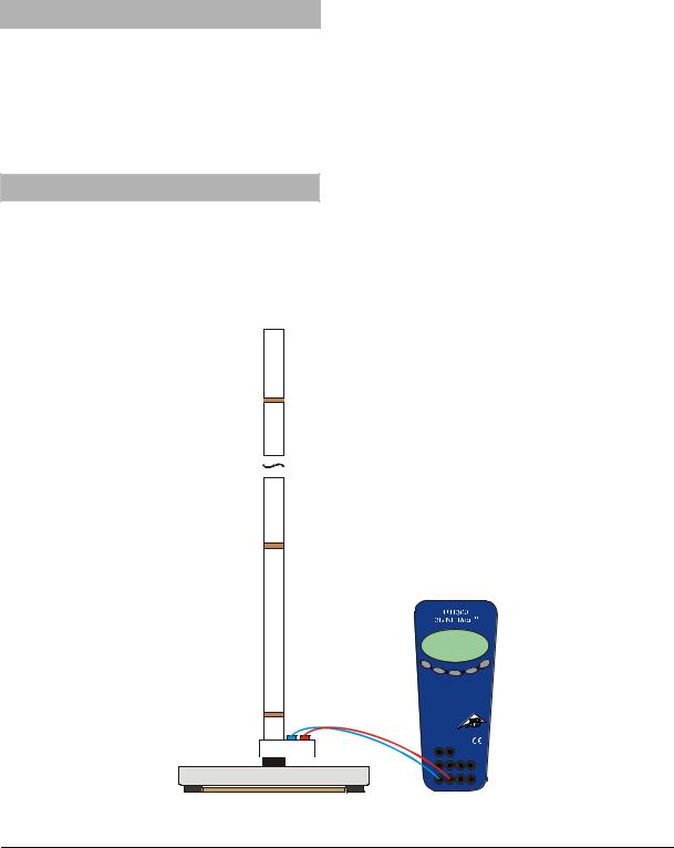
•Set up the experiment as shown in fig. 1.
•Connect leads between the connector sockets of
the tube and the voltage input UAIN on the interface.
•Connect the interface to the computer.
•Start the software program.
•Hold the bar magnet over the top opening of the tube.
•Start a measurement in the program and allow the bar magnet to fall.
•Evaluate the voltage curve.
Alternatively, the measurement may be carried out with an oscilloscope.
Fig. 1 Experiment set-up
2
 Loading...