


3B SCIENTIFIC® PHYSICS
Heat pump U8440600
Instruction sheet
12/08 ELWE/ALF
1 |
On/off switch for Compressor |
2 |
Condenser |
3 |
Stirrer |
4 |
Overpressure cut-out switch |
5 |
Reset overpressure cut-out switch |
6 |
Manometer for the high-pressure side |
7 |
Manometer for the low-pressure side |
8 |
Energy monitor |
9 |
Expansion valve |
10 |
Evaporator |
11 |
Stirrer |
12 |
Viewing window |
13 |
Compressor |
1. Safety instructions
If the heat pump is tipped to one side, it must remain in an upright position for at least seven hours before being operated again.
•Always keep the heat pump in an upright position during storage, transport and operation.
•Carry the heat pump only at the carrying handles.
•Do not lift the heat pump by its copper pipes or they may get bent.
Caution: the voltage in the compressor circuit is dangerous to touch!
•Do not thermally insulate the compressor or it may overheat.
•After shut-down by the overpressure cut-out switch wait for 10 minutes to press the green reset button.
2. Description
Demonstration model of an electrically powered compressor heat pump for demonstrating how a heat pump or a refrigerator operates. Can be operated as a water-air or water-water heat pump.
The demonstration model of an electrically powered compressor heat pump consists of a compressor with a drive motor, an evaporator, a condenser and an expansion valve. These components are connected in a closed system by means of pipes and built onto a base.
The energy monitor allows to record and display the electrical performance data of the compressor.
1
Button |
Function |
|
|
Zeit (Time) |
displays the time / operating time of |
|
the compresor (ED) |
|
(changes when you press the button) |
|
|
Strom (Cur- |
displays the current consumption of |
rent) |
the compresor |
|
|
Spannung |
displays the mains voltage |
(Voltage) |
|
|
|
Leistung |
displays the momentary power con- |
(Power) |
sumption |
|
|
Energie |
displays the energy, (unit: Wh) |
(Energy) |
|
|
|
Zeit (Time) |
Reset function for time, ED and |
> 6s |
energy |
|
|
The evaporator and condenser are constructed as coils of copper piping and each is immersed in a beaker filled with 2000 ml of water that serves as a reservoir of heat in order to determine the quantity of energy absorbed or emitted. Two additional thermometers are required in order to measure the temperature of the water in the beakers.
Two large manometers display the pressure of the refrigerant in both heat exchangers. An overpressure cut-out switch disconnects the heat pump from the mains if the excess pressure reaches 15 bars.
So that the properties of the refrigerant in liquid and gaseous states and the processes of conversion can be viewed, the heat pump is equipped with viewing windows. These allow the interior of the pump to be seen and the state of the refrigerant to be observed immediately after the evaporator or condenser.
The heat pump is available for two different mains volatages. U8440600-230 is designed for 230 V (±10 %), 50 Hz mains supplies, while the U8440600-115 model is for 115 V (±10 %), 60 Hz supplies.
3. Technical data
Compressor power: |
120 W, power consump |
|
tion dependent on operat- |
|
ing state |
Evaporator temperature: -10° C |
|
Refrigerant (CFC-free): |
R 134A (Tetrafluorethan, C2H2F4) |
Boiling point: |
-26° C |
Manometer: |
160 mm dia., evaporator |
|
(suction intake) up to 9 |
|
bars; condenser (pressure |
|
pipe) up to 24 bars |
Overpressure cut-off: |
disconnects compressor |
|
from the mains at 15 bars |
Power supply: |
115 V, 60 Hz or 230 V, 50 Hz |
Dimensions: |
750 x 350 x 540 mm3 |
Weight: |
21 kg approx. |
4.Operating principle
3.1The processes in a heat pump circuit
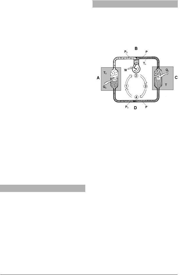
In the most important and widely used type of heat pump, the compressor heat pump, a substance in the form of a liquid with a low boiling point circulates in a closed loop. It passes through four different processes. It is evaporated, compressed, condensed and then allowed to expand (see Fig. 1).
Fig. 1 Circulation in a heat pump
AEvaporator
BCompressor
CCondenser
DExpansion valve
P0 |
Low pressure in the evaporator segment from |
|
the outlet of the expansion valve to the input |
of the compressor
pHigh pressure in the condenser segment from the outlet of the compressor to the input of the expansion valve
T0 |
Temperature of the medium (soil, water, air) |
|
surrounding the evaporator from which a |
quantity of heat Qa is absorbed
TTemperature of the medium (usually centrally heated water), surrounding the condenser which absorbs a quantity of heat Qz
T0* |
Boiling point of the refrigerant in the evapo- |
|
rator at pressure p0 |
Th |
Temperature of the refrigerant vapour |
|
after compression |
T* |
Boiling point of the refrigerant in the con- |
|
denser at pressure p |
Qa |
Heat absorbed by the evaporator |
QZ |
Heat emitted by the condenser |
W |
Work performed by the compressor |
3.1.1 Evaporation
In the evaporator the liquid refrigerant experiences a low pressure p0. The temperature T0 in the medium surrounding the evaporator is higher than the boiling point of the refrigerant T0* corresponding to the pressure p0. This tempera-
2
 Loading...