


I N
S |
|
T |
Q SERIES |
|
RUCT I O |
|
REACH-IN |
|
NS |
Q SERIES
REACH-IN
FOOD STORAGE CABINETS
701 S. RIDGE AVENUE
TROY, OHIO 45374-0001
937 332-3000
www.hobartcorp.com |
FORM 14580 Rev. L (Jan. 2002) |
Installation, Operation and Care of
Q SERIES REACH-IN FOOD STORAGE CABINETS
SAVE THESE INSTRUCTIONS
GENERAL
The Q Series Reach-In Food Storage Cabinets are available as low temperature (0°F), medium temperature (38°F) refrigeration units or hot food storage cabinets (180°F maximum). They may be ordered as one-, two-, or three-section cabinets.
A variety of optional cabinets is available. These include: Twoor three-section cabinets with a combination of medium and low temperature sections or medium temperature and hot food storage sections; twoor three section cabinets equipped with optional SAFE-T-THAW® equipment for safe, rapid thawing at medium temperatures; convertible models which, by setting a selector switch, will operate as either a low temperature or medium temperature unit; and single-section over/under cabinets which feature a medium temperature and a low temperature unit, one on top of the other.
INSTALLATION
UNPACKING AND ASSEMBLY
Immediately after unpacking the reach-in, check for possible shipping damage. If this unit is found to be damaged after unpacking, save the packaging material and contact the carrier within 15 days of delivery.
Prior to installation, test the electrical service to assure that it agrees with the specifications on the machine data plate located in the upper left corner inside the cabinet.
LOCATION
For optimum performance, the condensing unit of the reach-in (refrigeration models only) must have an adequate supply of air for cooling purposes. The operating location must provide either a minimum 12" clearance overhead of the condensing unit or the unrestricted flow of air at the back of the reach-in.
– 2 –

ASSEMBLY
Some components can be removed to allow the cabinet to pass through short or narrow doorways.
The door handle can be removed as follows:
1.Remove the screw and bolt from the tumbler.
2.Remove the two mounting screws and the handle assembly (Fig. 1)
|
MOUNTING SCREW |
|
ASSEMBLY |
HANDLE ASSEMBLY |
|
MOUNTING |
||
SCREW |
|
|
SCREW |
|
|
BOLT |
PLUG |
|
BUTTON |
||
|
||
DOOR |
PL-50949 |
|
|
KEY |
3. Replace in reverse order of disassembly.
Door(s) and hinges can be removed as follows:
1.Lift up and remove the front trim panel (Fig. 1).
2.Remove the screws which secure the trim rail cover (Fig. 1), unplug the door switch lead wires, and remove the screws which secure the trim rail (Fig. 1). Carefully lay the trim rail on top of the cabinet — avoid damaging or kinking the thermometer capillary tube.
3.Remove the three screws which secure the upper hinge plate to the cabinet (Fig. 2). This will remove hinge tension. Remove the nut underneath the lower hinge plate which secures the bottom hinge. Remove door. Remove lower hinge plate (Fig. 2).
FRONT TRIM PANEL
TRIM RAIL COVER
P L - 5 3 6 1 5
Fig. 2
Fig. 1
UPPER
HINGE
LOWER
HINGE
SCREWS
(3)
PL-53617
TRIM RAIL
Fig. 3
4.If the hinge mechanism should become uncocked while changing the door, it will be necessary to recock the hinge mechanism. To do this, remove the door from the cabinet and position the door face down on a workbench or table. Using a 5/16" open end or adjustable wrench, turn the hinge mechanism shaft 135° (Fig. 3).
5.Replace the hinge plates and door(s) in the reverse order of disassembly.
If cabinets are too tall, the refrigeration system may need to be removed in order to pass through short openings. Contact your dealer or authorized servicer if this becomes necessary.
UNCOCKED POSITION |
COCKED POSITION |
TURN 135 º |
135 º |
– POSITION |
1 – (LEFT - HAND HINGED DOOR) |
UNCOCKED POSITION |
COCKED POSITION |
TURN 135 º |
135 º |
– POSITION 2 – (RIGHT - HAND HINGED DOOR) POSITION DOOR IN ONE OF THE TWO POSITIONS SHOWN .
Fig. 4
Once the cabinet is in its final position, replace any components that may have been removed (door handle, etc.) and then level the cabinet front-to-back and side-to-side by adjusting the legs as required.
Door Hinging
Should the doors need to be rehinged (from right to left or vice versa), contact a Hobart-authorized Refrigeration Service Company.
– 3 –
LEGS OR CASTERS
WARNING: THE CABINET MUST BE BLOCKED AND STABLE BEFORE INSTALLING LEGS OR CASTERS.
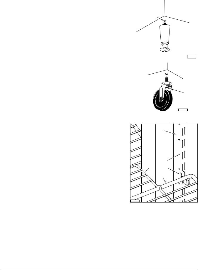
Legs (Fig. 5)
To install the legs, raise and block the reach-in a minimum of 7" from the floor and thread the legs into the Threaded Holes on the bottom of the cabinet. This unit must be level in order to operate properly. Turn the adjustable feet in or out as required to level the unit front-to-back and side-to-side.
NOTE: Three-section front opening cabinets come with five legs, the fifth leg should be placed in the front center threaded hole. In the case of a three section pass through cabinet, a sixth leg is included for the rear center hole. Failure to install these legs in the proper location may result in damage to the cabinet.
Casters (Fig. 6)
Use casters only on reach-in models with self-contained refrigeration systems that have cord and plug electrical connections. Raise and block the cabinet a minimum of 7" from the floor. Thread the casters into the holes in the bottom of the cabinet (Fig. 2). Casters with brake should be installed at the front. Securely tighten the caster with the octagon shaped Bolt head underneath — not the round flange on top.
Shelves (Fig. 7)
If purchased, the shelves and shelf clips are shipped with the cabinet. Insert the shelf clips into the pilaster and install the shelves. Index holes are provided in the pilaster to help in leveling the shelves.
Bonus shelves are provided to fill the space between the shelves. These are positioned and supported by the shelves.
NOTE: Loosen all thumbscrews which secure shelf pilasters and light cover(s) prior to placing product in cabinet. Thumbscrews should be loose enough to remove with your fingers so parts can be readily removed for cleaning without the use of tools. Failure to comply with this request will invalidate the NSF listing.
Utility Base (Optional)
THREADED HOLE
RAISE LOWER
Fig. 5 |
PL-56125 |
|
 BOLT
BOLT
PL-53353
Fig. 6
|
PILASTER |
COLD AIR |
|
DUCT |
|
|
INDEX |
BONUS |
HOLE |
|
|
SHELF |
SHELF |
|
CLIP |
|
SHELF |
PL-50910 

Fig. 7
If your unit comes with a utility base, we recommend securing the base to the floor to prevent damage to the floor outlet due to accidental movement. The utility base is secured to the cabinet with four bolts, one at each corner. The utility base is mounted at the factory. With the cabinet in its final installed and leveled position, apply a bead of NSF approved sealant (not supplied) around the bottom. Access covers, secured with screws, are provided on the left side and front for attaching the power supply cord to a floor outlet underneath the cabinet.
Curb
The cabinet may be installed on a curb without legs or casters; the typical curb must be recessed a minimum of 13/8" from the front of the cabinet (and rear if it is a pass through) to allow room for the hinges.
– 4 –
 Loading...