


 Loading...
Dell™ PowerConnect™ 2124 and 2508 Systems
User’s Guide
w w w. d e l l . c o m | s u p p o r t . d e l l . c o m

Notes, Notices, and Cautions
NOTE: A NOTE indicates important information that helps you make better use of your computer.
NOTICE: A NOTICE indicates either potential damage to hardware or loss of data and tells you how to avoid the problem.
 CAUTION: A CAUTION indicates a potential for property damage, personal injury, or death.
____________________
Information in this document is subject to change without notice. © 2002 Dell Computer Corporation. All rights reserved.
Reproduction in any manner whatsoever without the written permission of Dell Computer Corporation is strictly forbidden.
Trademarks used in this text: Dell, the DELL logo, DellNet, and PowerConnect are trademarks of Dell Computer Corporation.
Other trademarks and trade names may be used in this document to refer to either the entities claiming the marks and names or their products. Dell Computer Corporation disclaims any proprietary interest in trademarks and trade names other than its own.
September 2002 P/N 0P263 Rev. A02

Contents
1Caution: Safety Instructions 5
2Features 11
Package Contents 12
Front Panel Indicators 13
Connecting Devices 16
Aggregating Traffic at 1000-Mbps Gigabit Ethernet 17
Class-of-Service 18
Redundant Power System PowerConnect RPS-60 19
Mounting Kit Instructions 19
Technical Information 20
3 Help and Regulatory Notices 21
Technical Assistance 22
Problems With Your Order 24
Product Information 24
Returning Items for Warranty Repair or Credit 24
Before You Call 25
Contacting Dell 26
Contents 3

Regulatory Notices 42
4 Contents

Caution:
Safety
Instructions
Use the following safety guidelines to ensure your own personal safety and to help protect your system from potential damage.
General
•Observe and follow service markings. Do not service any product except as explained in your system documentation. Opening or removing covers that are marked with the triangular symbol with a lightning bolt may expose you to electrical shock.
Components inside these compartments should be serviced only by a trained service technician.
•If any of the following conditions occur, unplug the product from the electrical outlet and replace the part or contact your trained service provider:
–The power cable, extension cable, or plug is damaged.
–An object has fallen into the product.
–The product has been exposed to water.
–The product has been dropped or damaged.
–The product does not operate correctly when you follow the operating instructions.
•Keep your system away from radiators and heat sources. Also, do not block cooling vents.
•Do not spill food or liquids on your system components, and never operate the product in a wet environment. If the system gets wet, see the appropriate section in your troubleshooting guide or contact your trained service provider.
•Do not push any objects into the openings of your system. Doing so can cause fire or electric shock by shorting out interior components.
•Use the product only with approved equipment.
•Allow the product to cool before removing covers or touching internal components.
•Operate the product only from the type of external power source indicated on the electrical ratings label. If you are not sure of the type of power source required, consult your service provider or local power company.
Safety Instr uctions |
|
5 |
|

w w w. d e l l . c o m | s u p p o r t . d e l l . c o m
Caution:
Safety
Instructions
•Use only approved power cable(s). If you have not been provided with a power cable for your system or for any AC-powered option intended for your system, purchase a power cable that is approved for use in your country. The power cable must be rated for the product and for the voltage and current marked on the product's electrical ratings label. The voltage and current rating of the cable should be greater than the ratings marked on the product.
•To help prevent electric shock, plug the system and peripheral power cables into properly grounded electrical outlets. These cables are equipped with three-prong plugs to help ensure proper grounding. Do not use adapter plugs or remove the grounding prong from a cable. If you must use an extension cable, use a 3-wire cable with properly grounded plugs.
•Observe extension cable and power strip ratings. Make sure that the total ampere rating of all products plugged into the extension cable or power strip does not exceed 80 percent of the ampere ratings limit for the extension cable or power strip.
•To help protect your system from sudden, transient increases and decreases in electrical power, use a surge suppressor, line conditioner, or uninterruptible power supply (UPS).
•Position system cables and power cables carefully; route cables so that they cannot be stepped on or tripped over. Be sure that nothing rests on any cables.
•Do not modify power cables or plugs. Consult a licensed electrician or your power company for site modifications. Always follow your local/national wiring rules.
•When connecting or disconnecting power to hot-pluggable power supplies, if offered with your system, observe the following guidelines:
–Install the power supply before connecting the power cable to the power supply.
–Unplug the power cable before removing the power supply.
–If the system has multiple sources of power, disconnect power from the system by unplugging all power cables from the power supplies.
•Move products with care; ensure that all casters and/or stabilizers are firmly connected to the system. Avoid sudden stops and uneven surfaces.
Rack Mounting of Systems
6 Safety Instr uctions

Caution:
Safety
Instructions
Observe the following precautions for rack stability and safety. Also refer to the rack installation documentation accompanying the system and the rack for specific caution statements and procedures.
Systems are considered to be components in a rack. Thus, "component" refers to any system as well as to various peripherals or supporting hardware.
 CAUTION: Installing systems in a rack without the front and side stabilizers installed could cause the rack to tip over, potentially resulting in bodily injury under certain circumstances. Therefore, always install the stabilizers before installing components in the rack.
After installing system/components in a rack, never pull more than one component out of the rack on its slide assemblies at one time. The weight of more than one extended component could cause the rack to tip over and may result in serious injury.
NOTE: Your system is safety-certified as a free-standing unit and as a component for use in a Dell rack cabinet using the customer rack kit. The installation of your system and rack kit in any other rack cabinet has not been approved by any safety agencies. It is your responsibility to have the final combination of system and rack kit in a rack cabinet evaluated for suitability by a certified safety agency. Dell disclaims all liability and warranties in connection with such combinations.
•System rack kits are intended to be installed in a rack by trained service technicians. If you install the kit in any other rack, be sure that the rack meets the specifications of a Dell rack.
 CAUTION: Do not move racks by yourself. Due to the height and weight of the rack, a minimum of two people should accomplish this task.
•Before working on the rack, make sure that the stabilizers are secured to the rack, extended to the floor, and that the full weight of the rack rests on the floor. Install front and side stabilizers on a single rack or front stabilizers for joined multiple racks before working on the rack.
•Always load the rack from the bottom up, and load the heaviest item in the rack first.
•Make sure that the rack is level and stable before extending a component from the rack.
Safety Instr uctions |
|
7 |
|

w w w. d e l l . c o m | s u p p o r t . d e l l . c o m
Caution:
Safety
Instructions
•Use caution when pressing the component rail release latches and sliding a component into or out of a rack; the slide rails can pinch your fingers.
•After a component is inserted into the rack, carefully extend the rail into a locking position, and then slide the component into the rack.
•Do not overload the AC supply branch circuit that provides power to the rack. The total rack load should not exceed 80 percent of the branch circuit rating.
•Ensure that proper airflow is provided to components in the rack.
•Do not step on or stand on any component when servicing other components in a rack.
 CAUTION: A qualified electrician must perform all connections to DC power and to safety grounds. All electrical wiring must comply with applicable local or national codes and practices.
 CAUTION: Never defeat the ground conductor or operate the equipment in the absence of a suitably installed ground conductor. Contact the appropriate electrical inspection authority or an electrician if you are uncertain that suitable grounding is available.
 CAUTION: The system chassis must be positively grounded to the rack cabinet frame. Do not attempt to connect power to the system until grounding cables are connected. Completed power and safety ground wiring must be inspected by a qualified electrical inspector. An energy hazard will exist if the safety ground cable is omitted or disconnected.
Modems, Telecommunications, or Local Area Network Options
•Do not connect or use a modem during a lightning storm. There may be a risk of electrical shock from lightning.
•Never connect or use a modem in a wet environment.
•Do not plug a modem or telephone cable into the network interface controller (NIC) receptacle.
•Disconnect the modem cable before opening a product enclosure, touching or installing internal components, or touching an uninsulated modem cable or jack.
8 Safety Instr uctions

Caution:
Safety
Instructions
When Working Inside Your System
Protecting Against Electrostatic Discharge
Static electricity can harm delicate components inside your system. To prevent static damage, discharge static electricity from your body before you touch any of the electronic components, such as the microprocessor. You can do so by periodically touching an unpainted metal surface on the chassis.
You can also take the following steps to prevent damage from electrostatic discharge (ESD):
•When unpacking a static-sensitive component from its shipping carton, do not remove the component from the antistatic packing material until you are ready to install the component in your system. Just before unwrapping the antistatic packaging, be sure to discharge static electricity from your body.
•When transporting a sensitive component, first place it in an antistatic container or packaging.
•Handle all sensitive components in a static-safe area. If possible, use antistatic floor pads and workbench pads and an antistatic grounding strap.
NOTE: Your system may also include circuit cards or other components that contain batteries. These batteries must also be disposed of in a battery deposit site. For information about such batteries, refer to the documentation for the specific card or component.
Safety Instr uctions |
|
9 |
|

w w w . d e l l . c o m | s u p p o r t . d e l l . c o m
uctions Instr Safety 10
1
S E C T I O N 1
Fe a t u r e s
Package Contents
Front Panel Indicators
Connecting Devices
Aggregating Traffic at 1000-Mbps Gigabit Ethernet
Class-of-Service
Redundant Power System PowerConnect RPS-60
Mounting Kit Instructions
Technical Information
m o c . l l e d . t r o p p u s | m o c . l l e d .w w w

w w w. d e l l . c o m | s u p p o r t . d e l l . c o m
The PowerConnect 2124 and 2508 switches provide 24 10/100-Mbps Fast Ethernet ports plus 1 10/100/1000-Mbps Gigabit Ethernet port and
8 10/100/1000-Mbps Gigabit Ethernet ports, respectively. With complete switching features, including auto-sensing of line speed and autonegotiating of duplex mode, these switches offer smooth network migrations and easy upgrades to network capacity.
These switches have the following features:
•Complies with IEEE 802.3 10Base-T, IEEE 802.3u 100Base-TX, IEEE 802.3z/ab 1000Base-T
•24 10/100-Mbps plus 1 10/100/1000-Mbps switch ports (PowerConnect 2124)
•8 10/100/1000-Mbps switch ports (PowerConnect 2508)
•Automatic negotiation for speed and duplex mode on all ports
•Backpressure flow control in half-duplex operation
•IEEE 802.3x PAUSE frames flow control in full-duplex operation
•Auto MDI/MDIX
•8K MAC address entries supported with hardware-based address aging
•Tag-based 802.1p Class-of-Service with four priority queues per port
•Comprehensive LED indicator panel to monitor overall switching condition
•19-inch rack-mountable
•Standard 1U chassis
•Internal power supply
•Optional external redundant power supply with PowerConnect RPS-60
Package Contents
Before you install a switch, verify that your package contains the following items:
•Switch
•Self-adhesive rubber pads for desktop installation
12 Features

•Rack-mount kit for rack installation
•PowerConnect 2124 and 2508 User’s Guide
•AC power cord
Front Panel Indicators
The LEDs on the front panel display the following information:
•Status of the power supply
•Status of the optional external redundant power supply
•Connection speed of 10 Mbps, 100 Mbps or 1000 Mbps
•Data activity on the segment
•Fullor half-duplex operation mode
PowerConnect 2124
Power LED
•Green — The unit is on and the internal power supply is working properly.
•Red — The unit is on and the internal power supply has failed.
•Off — The unit is off.
Features 13

w w w. d e l l . c o m | s u p p o r t . d e l l . c o m
Redundant Power System (RPS) LED
•Green — The redundant power system is connected and working properly.
•Red — The redundant power system is connected, but failed.
•Off — The redundant power system is not connected.
10/100 Ports Link/Activity (LNK/ACT) LED
•Green — A 100-Mbps link has been established.
•Blinking Green — A 100-Mbps link has been established and data is being transmitted or received.
•Orange — A 10-Mbps link has been established.
•Blinking Orange — A 10-Mbps link has been established and data is being transmitted or received.
•Off — No link established.
10/100 Ports Duplex Mode/Collisions (FDX/COL) LED
•Green — The port is operating in full-duplex mode.
•Blinking Green — The port is operating in half-duplex mode and collisions are occurring.
•Off — The port is operating in half-duplex mode and no collisions are occurring.
10/100/1000 Port Gigabit (1000) LED
•Green — A 1000-Mbps link is established.
•Off — No 1000-Mbps link is established.
10/100/1000 Port Fast Ethernet (100) LED
•Green — A 100-Mbps link is established.
•Off — No 100-Mbps link is established.
14 Features
10/100/1000 Port Link/Activity (LNK/ACT) LED
•Green — A link has been established.
•Blinking Green — A link has been established and data is being transmitted or received.
•Off — No link established.
10/100/1000 Port Duplex Mode/Collisions (FDX/COL) LED
•Green — The port is operating in full-duplex mode.
•Blinking Green — The port is operating in half-duplex mode and collisions are occurring.
•Off — The port is operating in half-duplex mode and no collisions are occurring.
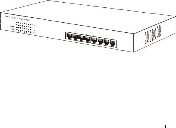
PowerConnect 2508
Power LED
•Green — The unit is on and the internal power supply is working properly.
•Red — The unit is on and the internal power supply has failed.
•Off — The unit is off.
Features 15
Loading...