


 Loading...
AT-9400 Series
Gigabit Ethernet
Switches
Layer 2+ |
AT-9408LC/SP |
|
AT-9424T/GB |
|
AT-9424T/SP |
Basic Layer 3 |
AT-9424T |
|
AT-9424T/POE |
|
AT-9424Ts |
|
AT-9424Ts/XP |
|
AT-9448T/SP |
|
AT-9448Ts/XP |
Installation Guide
613-000987 Rev. A
Copyright © 2007 Allied Telesis, Inc.
All rights reserved. No part of this publication may be reproduced without prior written permission from Allied Telesis, Inc.
Allied Telesis is a registered trademark of Allied Telesis, Incorporated. All other product names, company names, logos or other designations mentioned herein are trademarks or registered trademarks of their respective owners.
Allied Telesis, Inc. reserves the right to make changes in specifications and other information contained in this document without prior written notice. The information provided herein is subject to change without notice. In no event shall Allied Telesis, Inc. be liable for any incidental, special, indirect, or consequential damages whatsoever, including but not limited to lost profits, arising out of or related to this manual or the information contained herein, even if Allied Telesis, Inc. has been advised of, known, or should have known, the possibility of such damages.

Electrical Safety and Emissions Standards
This product meets the following standards.
U.S. Federal Communications Commission
Radiated Energy
Note: This equipment has been tested and found to comply with the limits for a Class A digital device pursuant to Part 15 of FCC Rules. These limits are designed to provide reasonable protection against harmful interference when the equipment is operated in a commercial environment. This equipment generates, uses, and can radiate radio frequency energy and, if not installed and used in accordance with this instruction manual, may cause harmful interference to radio communications. Operation of this equipment in a residential area is likely to cause harmful interference in which case the user will be required to correct the interference at his own expense.
Note: Modifications or changes not expressly approved of by the manufacturer or the FCC, can void your right to operate this equipment.
Industry Canada
This Class A digital apparatus complies with Canadian ICES-003.
Cet appareil numérique de la classe A est conforme à la norme NMB-003 du Canada.
RFI Emissions |
FCC Class A, EN55022 Class A, EN61000-3-2, EN61000-3-3, VCCI |
|
Class A, C-TICK, CE |
Warning: In a domestic environment this product may cause radio interference in which case the user may be required to take adequate measures.
|
EMC (Immunity) |
EN55024 |
|
Electrical Safety |
EN60950 (TUV), UL 60950 (CULUS) |
|
Laser Safety |
EN60825 |
|
||
|
|
|
3

Translated Safety Statements
Important: The indicates that a translation of the safety statement is available in a PDF document titled “Translated Safety Statements” (613-000990) posted on the Allied Telesis website at www.alliedtelesis.com. This document is also included with the documentation CD that is shipped with the product.
4

Contents
Preface .................................................................................................................................................................................. |
7 |
Product Documentation .......................................................................................................................................................... |
8 |
Where to Go First ................................................................................................................................................................... |
9 |
Starting a Management Session .......................................................................................................................................... |
10 |
Safety Symbols Used in this Document................................................................................................................................ |
11 |
Where to Find Web-based Guides ....................................................................................................................................... |
12 |
Contacting Allied Telesis ...................................................................................................................................................... |
13 |
Online Support .............................................................................................................................................................. |
13 |
Email and Telephone Support....................................................................................................................................... |
13 |
Returning Products........................................................................................................................................................ |
13 |
For Sales or Corporate Information............................................................................................................................... |
13 |
Warranty........................................................................................................................................................................ |
13 |
Management Software Updates.................................................................................................................................... |
13 |
Chapter 1: Overview .......................................................................................................................................................... |
15 |
Descriptions.......................................................................................................................................................................... |
17 |
AT-9408LC/SP Switch................................................................................................................................................... |
17 |
AT-9424T/GB Switch..................................................................................................................................................... |
18 |
AT-9424T/SP Switch ..................................................................................................................................................... |
19 |
AT-9424T Switch........................................................................................................................................................... |
20 |
AT-9424T/POE Switch .................................................................................................................................................. |
21 |
AT-9424Ts Switch ......................................................................................................................................................... |
22 |
AT-9424Ts/XP Switch ................................................................................................................................................... |
23 |
AT-9448T/SP Switch ..................................................................................................................................................... |
24 |
AT-9448Ts/XP Switch ................................................................................................................................................... |
25 |
10/100/1000Base-T Twisted Pair Ports................................................................................................................................ |
26 |
Connector Type............................................................................................................................................................. |
26 |
Speed ............................................................................................................................................................................ |
26 |
Duplex Mode ................................................................................................................................................................. |
26 |
Maximum Distance........................................................................................................................................................ |
27 |
Cable Type .................................................................................................................................................................... |
27 |
Auto-MDI/MDI-X ............................................................................................................................................................ |
27 |
Port Pinouts................................................................................................................................................................... |
27 |
Fiber Optic Ports................................................................................................................................................................... |
28 |
Connector Type............................................................................................................................................................. |
28 |
Speed ............................................................................................................................................................................ |
28 |
Maximum Distance and Cabling.................................................................................................................................... |
28 |
GBIC Transceiver Slots ........................................................................................................................................................ |
29 |
SFP Transceiver Slots.......................................................................................................................................................... |
30 |
XFP Transceiver Slots.......................................................................................................................................................... |
31 |
Redundant Twisted Pair Ports.............................................................................................................................................. |
32 |
Compact Flash Card Slot...................................................................................................................................................... |
34 |
Port LEDs ............................................................................................................................................................................. |
35 |
10/100/1000Base-T Twisted Pair Port LEDs................................................................................................................. |
35 |
Fiber Optic Port and Transceiver Slot LEDs.................................................................................................................. |
36 |
System LEDs........................................................................................................................................................................ |
37 |
Stack LEDs........................................................................................................................................................................... |
38 |
Expansion Slot...................................................................................................................................................................... |
39 |
Terminal Port ........................................................................................................................................................................ |
40 |
Power Over Ethernet ............................................................................................................................................................ |
41 |
5
Contents |
|
Power Budgeting ........................................................................................................................................................... |
41 |
Implementation .............................................................................................................................................................. |
42 |
AT-RPS3204 Redundant Power Supply............................................................................................................................... |
43 |
AC Power Connector ............................................................................................................................................................ |
44 |
Chapter 2: Installing the Switch ....................................................................................................................................... |
45 |
Reviewing Safety Precautions .............................................................................................................................................. |
46 |
Selecting a Site..................................................................................................................................................................... |
49 |
Twisted Pair and Fiber Optic Cable Specifications............................................................................................................... |
50 |
Twisted Pair Cable Specifications ................................................................................................................................. |
50 |
Fiber Optic Cable Specifications.................................................................................................................................... |
51 |
Optional Transceiver Cable Specifications.................................................................................................................... |
51 |
Unpacking the Switch ........................................................................................................................................................... |
52 |
Installing the Power Cord Retaining Clip (AC Switches Only) .............................................................................................. |
53 |
Installing the Switch in a Rack .............................................................................................................................................. |
54 |
Installing Optional Transceivers............................................................................................................................................ |
56 |
Installing a GBIC Transceiver........................................................................................................................................ |
56 |
Installing an SFP Transceiver........................................................................................................................................ |
57 |
Installing an XFP Transceiver........................................................................................................................................ |
59 |
Cabling the Twisted Pair or Fiber Optic Ports....................................................................................................................... |
61 |
Applying AC Power............................................................................................................................................................... |
62 |
Starting a Local Management Session ................................................................................................................................. |
64 |
Warranty Registration ........................................................................................................................................................... |
66 |
Chapter 3: Troubleshooting .............................................................................................................................................. |
67 |
Power LED is Off .................................................................................................................................................................. |
68 |
Twisted Pair Port Link LED is Off.......................................................................................................................................... |
69 |
Fiber Optic Port Link LED is Off............................................................................................................................................ |
70 |
Transceiver is Installed but the Status is “Not Present”........................................................................................................ |
71 |
System Fault LED is Blinking................................................................................................................................................ |
72 |
System Fault LED is Steadily On.......................................................................................................................................... |
73 |
Cannot Establish a Local (Out-of-Band) Management Session ........................................................................................... |
74 |
Switch Functions Intermittently ............................................................................................................................................. |
75 |
Appendix A: Technical Specifications ............................................................................................................................. |
77 |
Physical Specifications ......................................................................................................................................................... |
77 |
Environmental Specifications................................................................................................................................................ |
78 |
Power Specifications............................................................................................................................................................. |
79 |
Certifications ......................................................................................................................................................................... |
79 |
RJ-45 Twisted Pair Port Pinouts........................................................................................................................................... |
80 |
AT-9408LC/SP Switch 1000Base-SX Port Specifications .................................................................................................... |
82 |
RJ-45 Style Serial Terminal Port Pinouts.............................................................................................................................. |
83 |
RPS 21-pin D-combo Port and Connector Pinouts............................................................................................................... |
83 |
6

Preface
This guide contains the installation instructions for the AT-9400 Layer 2+ and Basic Layer 3 Gigabit Ethernet Switches. This preface contains the following sections:
“Product Documentation” on page 8
“Where to Go First” on page 9
“Starting a Management Session” on page 10
“Safety Symbols Used in this Document” on page 11
“Where to Find Web-based Guides” on page 12
“Contacting Allied Telesis” on page 13
7

Preface
Product Documentation
For overview information on the features of the AT-9400 Switch and the
AT-S63 Management Software, refer to:
AT-S63 Management Software Features Guide (PN 613-000801)
For instructions on starting a local or remote management session, refer to:
Starting an AT-S63 Management Session Guide (PN 613-000817)
For instructions on installing or managing stand-alone switches, refer to:
AT-S63 Management Software Menus Interface User’s Guide (PN 613-50570-00)
AT-S63 Management Software Command Line Interface User’s Guide (PN 613-50571-00)
AT-S63 Management Software Web Browser Interface User’s Guide (PN 613-50592-00)
For instructions on installing or managing a stack of AT-9400 Basic Layer 3 Switches and the AT-StackXG Stacking Module, refer to:
AT-9400 Stack Installation Guide (PN 613-000796)
AT-S63 Stack Command Line Interface User’s Guide (PN 613-000777)
8

AT-9400 Series Gigabit Ethernet Switches Installation Guide
Where to Go First
Allied Telesis recommends that you read Chapter 1, Overview, in the
AT-S63 Management Software Features Guide before you begin to manage the switch for the first time. There you will find a variety of basic information about the unit and the management software, like the two levels of manager access levels and the different types of management sessions.
The AT-S63 Management Software Features Guide is also your resource for background information on the features of the switch. You can refer there for the relevant concepts and guidelines when you configure a feature for the first time.
9

Preface
Starting a Management Session
For instructions on how to start a local or remote management session on the AT-9400 Switch, refer to the Starting an AT-S63 Management Session Guide.
10
AT-9400 Series Gigabit Ethernet Switches Installation Guide
Safety Symbols Used in this Document
This document uses the safety symbols defined in Table 1.
|
|
|
|
Table 1. Safety Symbols |
|
|
|
|
|
Symbol |
Meaning |
Description |
||
|
|
|
|
|
|
|
|
|
|
|
|
|
Caution |
Performing or omitting a specific action may |
|
|
|
||
|
|
|
|
result in equipment damage or loss of data. |
|
|
|
|
|
|
|
|
Warning |
Performing or omitting a specific action may |
|
|
|
||
|
|
|
|
result in electrical shock. |
|
|
|
|
|
11

Preface
Where to Find Web-based Guides
The installation and user guides for all Allied Telesis products are available in portable document format (PDF) on our web site at www.alliedtelesis.com. You can view the documents online or download them onto a local workstation or server.
12

AT-9400 Series Gigabit Ethernet Switches Installation Guide
Contacting Allied Telesis
Online Support
Email and
Telephone
Support
Returning
Products
For Sales or
Corporate
Information
Warranty
Management
Software Updates
This section provides Allied Telesis contact information for technical support as well as sales or corporate information.
You can request technical support online by accessing the Allied Telesis Knowledge Base from the following web site: www.alliedtelesis.com/support. You can use the Knowledge Base to submit questions to our technical support staff and review answers to previously asked questions.
For Technical Support via email or telephone, refer to the Allied Telesis web site: www.alliedtelesis.com. Select your country from the list displayed on the website. Then select the appropriate menu tab.
Products for return or repair must first be assigned a Return Materials Authorization (RMA) number. A product sent to Allied Telesis without a RMA number will be returned to the sender at the sender’s expense.
To obtain an RMA number, contact the Allied Telesis Technical Support group at our web site: www.alliedtelesis.com/support/rma. Select your country from the list displayed on the website. Then select the appropriate menu tab.
You can contact Allied Telesis for sales or corporate information at our web site: www.alliedtelesis.com. Select your country from the list displayed on the website. Then select the appropriate menu tab.
The AT-9400 Switch has a Lifetime Warranty (two years fan and PSU). Go to www.alliedtelesis.com/warranty for the specific terms and conditions of the warranty and for warranty registration.
New releases of management software for our managed products are available from either of the following Internet sites:
r Allied Telesis web site: www.alliedtelesis.com
r Allied Telesis FTP server: ftp://ftp.alliedtelesis.com
If you prefer to download new software from the Allied Telesis FTP server from your workstation’s command prompt, you will need FTP client software and you must log in to the server. Enter “anonymous” for the user name and your email address for the password.
13
Preface
14

Chapter 1
Overview
The AT-9400 Switches are managed Gigabit Ethernet switches for
Ethernet, Fast Ethernet, and Gigabit Ethernet networks. The AT-9400
Switches are divided into two groups:
Layer 2+ Switches
–AT-9408LC/SP
–AT-9424T/GB
–AT-9424T/SP
Basic Layer 3 Switches
–AT-9424T
–AT-9424T/POE
–AT-9424Ts
–AT-9424Ts/XP
–AT-9448T/SP
–AT-9448Ts/XP
The differences between the two groups are explained in the AT-S63
Management Software Features Guide.
This chapter has the following sections:
“Descriptions” on page 17
“10/100/1000Base-T Twisted Pair Ports” on page 26
“Fiber Optic Ports” on page 28
“GBIC Transceiver Slots” on page 29
“SFP Transceiver Slots” on page 30
“XFP Transceiver Slots” on page 31
“Redundant Twisted Pair Ports” on page 32
“Compact Flash Card Slot” on page 34
“Port LEDs” on page 35
“System LEDs” on page 37
“Stack LEDs” on page 38
“Expansion Slot” on page 39
“Terminal Port” on page 40
15
Chapter 1: Overview
“Power Over Ethernet” on page 41
“AT-RPS3204 Redundant Power Supply” on page 43
“AC Power Connector” on page 44
16

AT-9400 Series Gigabit Ethernet Switches Installation Guide
Descriptions
The following sections describe the AT-9400 Switches.
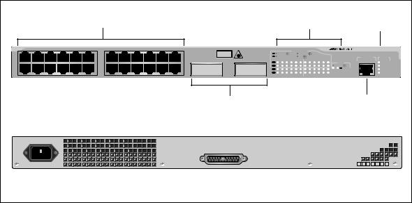
AT-9408LC/SP
Switch
The AT-9408LC/SP Layer 2+ Switch has the following hardware features:
Eight 1000Base-SX fiber optic ports with LC-duplex connectors
Four small form-factor pluggable (SFP) transceiver slots
An RJ-45 style serial terminal port for local (out-of-band) management
Status LEDs for the ports, SFP transceiver slots, and system
Redundant power supply (RPS) connector
Compact flash card slot
The front and back panels of the AT-9408LC/SP Switch are shown in Figure 1.
1000Base-SX Fiber Optic Ports |
SFP Transceiver Slots |
System LEDs |
||||
|
|
|
|
|
|
|
|
|
|
|
|
|
|
1 |
L/A |
L/A |
|
2 |
L/A |
3 |
4 |
L/A |
L/A |
|
5 |
6 |
L/A |
L/A |
|
7 |
L/A |
8 |


 AT-9408LC/SP Gigabit Ethernet Switch
|
|
|
|
CLASS 1 |
|
STATUS |
|
|
|
|
LASER PRODUCT |
TERMINAL |
|
|
|
|
|
|
PORT |
|
SFP |
SFP |
SFP |
SFP |
COMPACT FLASH |
|
FAULT |
L/A |
L/A |
L/A |
L/A |
PORT ACTIVITY |
EJECT |
MASTER |
|
||||||
|
|
|
|
L/A LINK / ACT |
|
RPS |
|
|
|
|
|
|
POWER |
9 |
10 |
11 |
12 |
|
|
|
|
|
|
|
|
461 |
|
|
|
|
|
|
|
|
Port LED (one per port) |
Compact Flash |
RJ-45 Style |
||||
|
|
Card Slot |
Serial |
|||
|
|
|
|
Terminal Port |
||
100-240VAC~
RPS INPUT
462
AC Power Connector |
RPS Connector |
Figure 1 AT-9408LC/SP Switch - Front and Back Panels
17
Chapter 1: Overview
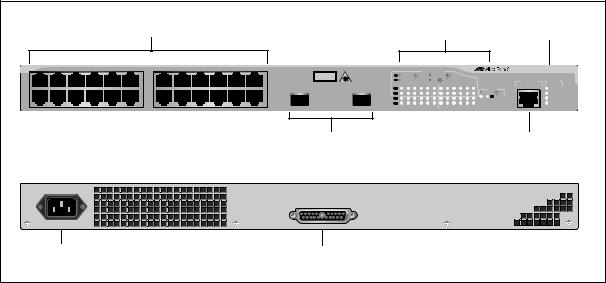
AT-9424T/GB
Switch
The AT-9424T/GB Layer 2+ Switch has the following hardware features:
24 10/100/1000Base-T ports
Two gigabit interface connector (GBIC) transceiver slots
An RJ-45 style serial terminal port for local (out-of-band) management
Status LEDs for the ports, transceiver slots, and system
Redundant power supply connector
Figure 2 shows the front and back panels of the AT-9424T/GB Switch.
|
Port and Transceiver |
System |
|
10/100/1000Base-T Ports |
Slot LEDs |
||
LEDs |
|||
|
|
1 |
3 |
5 |
7 |
9 |
11 |
|
13 |
15 |
17 |
19 |
21 |
23R |
|
|
|
|
|
|
|
|
|
|
|
|
|
2 |
4 |
6 |
8 |
10 |
12 |
|
14 |
16 |
18 |
20 |
22 |
24R |
CLASS 1
LASER PRODUCT
GBIC |
23 |
|
|
|
|
PORT ACTIVITY |
|
|
|
|
|
AT-9424T/GB Gigabit Ethernet Switch |
||||
L/A |
1000 LINK / |
|
ACT |
|
10/100 LINK / |
|
ACT |
|
|
|
|
|
||
D/C |
FDX |
|
|
|
|
HDX / |
COL |
|
|
|
|
TERMINAL |
STATUS |
|
|
1 |
3 |
5 |
7 |
9 |
11 |
13 |
15 |
17 |
19 |
21 |
23R |
PORT |
|
GBIC |
L/A |
|
|
|
|
|
|
|
|
|
|
|
GBIC |
|
FAULT |
|
|
|
|
|
|
|
|
|
|
|
|
|
|||
|
D/C |
|
|
|
|
|
|
|
|
|
|
|
1000 LINK / |
ACT |
MASTER |
|
L/A |
|
|
|
|
|
|
|
|
|
|
|
L/A |
|
RPS |
|
|
|
|
|
|
|
|
|
|
|
23 |
24 |
|
||
|
|
|
|
|
|
|
|
|
|
|
|
|
POWER |
||
|
D/C |
|
|
|
|
|
|
|
|
|
|
|
|
|
|
24 |
2 |
4 |
6 |
8 |
10 |
12 |
14 |
16 |
18 |
20 |
22 |
24R |
|
|
|
|
|
|
|
|
|
|
|
|
|
|
|
|
|
|
GBIC Transceiver Slots |
RJ-45 Style Serial |
|
Terminal Port |
100-240VAC~
RPS INPUT
|
|
|
|
|
|
|
|
|
|
|
|
|
|
|
|
|
|
|
|
|
|
|
|
|
|
|
|
|
|
|
|
|
|
|
|
|
|
|
|
|
|
|
|
|
|
|
|
|
|
|
|
|
|
|
|
|
|
|
|
|
|
|
|
|
|
|
|
|
|
|
|
|
|
|
|
|
|
|
|
|
|
|
|
|
|
|
|
|
|
|
|
|
|
|
|
|
|
|
|
|
|
|
|
|
|
|
|
|
|
|
|
|
|
|
|
|
|
|
|
|
|
|
|
|
|
|
|
|
|
|
|
|
|
|
|
|
|
|
|
|
|
|
|
|
|
|
|
|
|
|
|
|
|
|
|
|
|
|
|
|
|
|
|
|
|
|
|
|
|
|
|
|
|
|
|
|
|
|
|
|
|
|
|
|
|
|
|
|
|
|
|
|
|
|
|
|
|
|
|
|
|
|
|
|
|
|
|
|
|
|
|
|
|
|
|
|
|
|
|
|
|
|
|
|
|
|
|
|
|
|
|
|
|
|
|
|
|
|
|
|
|
|
|
|
|
|
|
|
|
|
|
|
|
|
|
|
|
|
|
|
|
|
|
|
|
|
|
|
|
|
|
|
|
|
|
|
|
|
|
|
|
|
|
|
|
|
|
|
|
|
|
|
|
|
|
|
|
|
|
|
|
|
|
|
|
|
|
|
|
|
|
|
|
|
|
|
|
|
|
|
|
|
|
|
AC Power |
|
|
|
|
|
|
|
|
|
|
|
|
|
|
|
|
|
|
|
|
|
RPS Connector |
|
|
|
|
|
|
|
|
|
|
|
|
|
|
|
|
|
|
||||||||||||||||||||||||
Connector |
|
|
|
|
|
|
|
|
|
|
|
|
|
|
|
|
|
|
|
|
|
|
|
|
|
|
|
|
|
|
|
|
|
|
|
|
|
|
|
|||||||||||||||||||||||||
|
|
|
|
|
|
|
|
|
|
|
|
|
|
|
|
|
|
|
|
|
|
|
|
|
|
|
|
|
|
|
|
|
|
|
|
|
|
|
|
|
||||||||||||||||||||||||
Figure 2 AT-9424T/GB Switch - Front and Back Panels
18
AT-9400 Series Gigabit Ethernet Switches Installation Guide
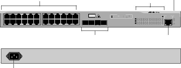
AT-9424T/SP
Switch
The hardware features of the AT-9424T/SP Layer 2+ Switch include:
24 10/100/1000Base-T ports
Two Gigabit Ethernet small form-factor pluggable (SFP) transceiver slots
An RJ-45 style serial terminal port for local (out-of-band) management
Status LEDs for the ports, transceiver slots, and system
Redundant power supply connector
Figure 3 shows the front and back panels of the AT-9424T/SP Switch.
|
|
|
10/100/1000Base-T Ports |
|
|
|
|
|
Port and SFP |
|
|
System |
|||||||||||||||||
|
|
|
|
|
|
|
|
|
|
Slot LEDs |
|
|
LEDs |
||||||||||||||||
1 |
3 |
5 |
7 |
9 |
11 |
13 |
15 |
17 |
19 |
21 |
23R |
|
|
|
|
|
PORT ACTIVITY |
|
|
|
|
|
|
|
AT-9424T/SP Gigabit Ethernet Switch |
||||
|
|
|
|
|
|
|
|
|
|
|
|
CLASS 1 |
L/A |
1000 LINK / |
|
ACT |
|
10/100 LINK / |
|
ACT |
|
|
|
|
|
|
|
||
|
|
|
|
|
|
|
|
|
|
|
|
LASER PRODUCT |
|
FDX |
|
|
|
|
HDX / |
COL |
|
|
|
|
|
|
|
|
|
|
|
|
|
|
|
|
|
|
|
|
|
|
D/C |
|
|
|
|
|
|
|
|
|
|
TERMINAL |
STATUS |
||||
|
|
|
|
|
|
|
|
|
|
|
|
|
|
1 |
3 |
5 |
7 |
9 |
11 |
13 |
15 |
17 |
19 |
21 |
23R |
|
|
PORT |
|
|
|
|
|
|
|
|
|
|
|
|
|
SFP |
L/A |
|
|
|
|
|
|
|
|
|
|
|
|
SFP |
|
|
FAULT |
|
|
|
|
|
|
|
|
|
|
|
|
SFP |
|
|
|
|
|
|
|
|
|
|
|
|
1000 LINK / |
ACT |
|
MASTER |
|
|
|
|
|
|
|
|
|
|
|
|
|
|
D/C |
|
|
|
|
|
|
|
|
|
|
|
|
|
|||
|
|
|
|
|
|
|
|
|
|
|
|
|
L/A |
|
|
|
|
|
|
|
|
|
|
|
|
L/A |
|
|
RPS |
|
|
|
|
|
|
|
|
|
|
|
|
|
|
|
|
|
|
|
|
|
|
|
|
23 |
24 |
|
|
||
|
|
|
|
|
|
|
|
|
|
|
|
|
|
|
|
|
|
|
|
|
|
|
|
|
|
|
POWER |
||
|
|
|
|
|
|
|
|
|
|
|
|
|
D/C |
|
|
|
|
|
|
|
|
|
|
|
|
|
|
|
|
2 |
4 |
6 |
8 |
10 |
12 |
14 |
16 |
18 |
20 |
22 |
24R |
23 |
24 |
2 |
4 |
6 |
8 |
10 |
12 |
14 |
16 |
18 |
20 |
22 |
24R |
|
|
|
|
|
|
|
|
|
|
|
|
|
|
|
|
|
|
|
|
||||||||||||||
|
|
|
|
|
|
|
|
|
|
|
|
SFP Transceiver Slots |
|
|
|
|
|
|
|
|
|
|
|
RJ-45 Style Serial |
|||||
|
|
|
|
|
|
|
|
|
|
|
|
|
|
|
|
|
|
|
|
|
|
|
|
|
|
Terminal Port |
|||
|
100-240VAC~ |
|
|
|
|
|
|
|
|
|
|
|
|
|
|
|
|
|
|
|
|
|
|
|
|
|
|
|
|
|
|
|
|
|
|
|
|
|
|
|
|
RPS INPUT |
|
|
|
|
|
|
|
|
|
|
|
|
|
|
|
|
|
AC Power |
|
|
|
|
|
|
|
|
RPS Connector |
|
|
|
|
|
|
|
|
|
|
|
|
|
|
|
|
||||
Connector |
|
|
|
|
|
|
|
|
|
|
|
|
|
|
|
|
|
|
|
|
|
|
|
|
|
|
|||
Figure 3 AT-9424T/SP Switch - Front and Back Panels
19
Chapter 1: Overview
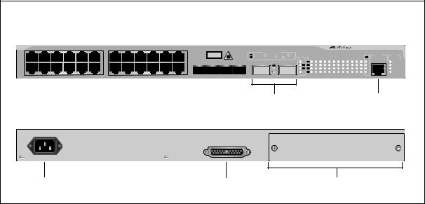
AT-9424T Switch The AT-9424T Basic Layer 3 Switch has these hardware features:
24 10/100/1000Base-T ports
Four Gigabit Ethernet small form-factor pluggable (SFP) transceiver slots
An RJ-45 style serial terminal port for local (out-of-band) management
Status LEDs for the ports, transceiver slots, and system
Figure 6 shows the front and back panels of the AT-9424T Switch.
|
|
10/100/1000Base-T Ports |
|
|
|
|
|
|
|
|
Port and SFP |
System |
|||||||||||||||
|
|
|
|
|
|
|
|
|
|
LEDs |
|||||||||||||||||
|
|
|
|
|
|
|
|
|
|
|
Slot LEDs |
||||||||||||||||
|
|
|
|
|
|
|
|
|
|
|
|
|
|
|
|
|
|
||||||||||
|
|
|
|
|
|
|
|
|
|
|
|
|
|
|
|
|
|
|
|||||||||
|
|
|
|
|
|
|
|
|
|
|
|
|
|
|
|
|
|
|
|
|
|
|
|
|
|
AT-9424T Gigabit Ethernet Switch |
|
|
|
|
|
|
|
|
|
|
|
|
|
|
|
|
|
PORT ACTIVITY |
|
|
|
|
|
|
|
|
|
|
|
|
|
|
|
|
|
|
|
|
|
|
|
|
|
|
L/A 1000 LINK / |
ACT 10/100 LINK / ACT |
|
|
|
|
|
|
|
|
|
SFP |
TERMINAL STATUS |
|
|
|
|
|
|
|
|
|
|
|
|
|
|
|
D/C FDX |
HDX / COL |
|
|
|
|
|
|
|
|
|
L/A |
PORT |
|
|
|
|
|
|
|
|
|
|
|
|
|
|
|
|
1 |
3 |
5 |
7 |
9 |
11 |
13 |
15 |
17 |
19 |
21R 23R |
|
|
|
|
|
|
|
|
|
|
|
|
|
|
|
SFP |
|
L/A |
|
|
|
|
|
|
|
|
|
21 |
FAULT |
|
|
|
|
|
|
|
|
|
|
|
|
|
|
|
|
|
|
|
|
|
|
|
|
|
|
|
|
|
|
|
|
|
|
|
|
|
|
|
|
|
|
|
|
D/C |
|
|
|
|
|
|
|
|
|
22 |
MASTER |
|
|
|
|
|
|
|
|
|
|
|
|
|
|
|
|
L/A |
|
|
|
|
|
|
|
|
|
23 |
|
|
|
|
|
|
|
|
|
|
|
|
|
|
|
|
|
D/C |
|
|
|
|
|
|
|
|
|
24 |
POWER |
2 |
4 |
6 |
8 |
10 |
12 |
14 |
16 |
18 |
20 |
22R |
24R |
21 |
22 |
23 |
24 |
2 |
4 |
6 |
8 |
10 |
12 |
14 |
16 |
18 |
20 |
22R 24R |
|
|
|
|
|
|
|
|
|
|
|
|
|
||||||||||||||||
|
|
|
|
|
|
|
|
|
|
|
|
|
|
|
|
|
|
|
|
|
|
|
|
|
|
|
1282 |
|
|
|
|
|
|
|
|
|
|
|
SFP Transceiver Slots |
|
|
|
|
|
|
|
RJ-45 Style Serial |
||||||||
|
|
|
|
|
|
|
|
|
|
|
|
|
|
|
|
|
|
|
|
|
|
|
|
|
Terminal Port |
||
100-240VAC~
1283
AC Power
Connector
Figure 4 AT-9424T Switch - Front and Back Panels
20
AT-9400 Series Gigabit Ethernet Switches Installation Guide
AT-9424T/POE
Switch
The AT-9424T/POE Basic Layer 3 Switch has these hardware features:
24 10/100/1000Base-T ports with Power over Ethernet (PoE) capability. (For a description of this feature, refer to “Power Over Ethernet,” on page
Four Gigabit Ethernet small form-factor pluggable (SFP) transceiver slots
An RJ-45 style serial terminal port for local (out-of-band) management
Status LEDs for the ports, transceiver slots, and system
Figure 5 shows the front and back panels of the AT-9424T/POE Switch
|
|
10/100/1000Base-T POE Ports |
|
|
|
|
Port and SFP |
|
System |
|||||||||||||||||
|
|
|
|
|
|
|
|
Slot LEDs |
|
LEDs |
||||||||||||||||
|
|
|
|
|
|
|
|
|
|
|
|
|
|
|
|
|
||||||||||
1 |
3 |
5 |
7 |
9 |
11 |
13 |
15 |
17 |
19 |
21R |
23R |
|
|
|
|
|
1000 LINK |
|
ACT |
10/100 LINK |
|
ACT |
|
|
AT-9424T/POE Layer 3 Gigabit Ethernet Switch |
|
|
|
|
|
|
|
|
|
|
|
|
|
CLASS 1 |
|
|
|
|
FDX |
|
|
HDX |
|
|
COL |
|
|
|
|
|
|
|
|
|
|
|
|
|
|
|
LASER PRODUCT |
|
|
|
|
PD ON |
|
|
PD ERR |
|
MAX CURRENT |
|
|
||
|
|
|
|
|
|
|
|
|
|
|
|
|
|
|
|
|
|
|
|
|
MODE TERMINAL PORT STATUS |
|||||
|
|
|
|
|
|
|
|
|
|
|
|
|
|
|
|
|
|
|
|
|
|
|
|
SFP |
||
|
|
|
|
|
|
|
|
|
|
|
|
1000 Base-X |
|
1 |
3 |
5 |
7 |
9 |
11 |
13 |
15 |
17 |
19 |
21R 23R |
|
|
|
|
|
|
|
|
|
|
|
|
|
|
|
|
|
|
|
|
|
|
|
|
|
21 |
|
FAULT |
|
|
|
|
|
|
|
|
|
|
|
|
21 |
22 |
23 |
24 |
|
|
|
|
|
|
|
|
|
22 |
|
MASTER |
|
|
|
|
|
|
|
|
|
|
|
|
|
|
|
|
|
|
|
|
|
|
|
|
23 |
|
|
|
|
|
|
|
|
|
|
|
|
|
|
|
|
|
|
|
|
|
|
|
|
|
|
24 |
|
POWER |
2 |
4 |
6 |
8 |
10 |
12 |
14 |
16 |
18 |
20 |
22R |
24R |
|
|
2 |
4 |
6 |
8 |
10 |
12 |
14 |
16 |
18 |
20 |
22R 24R |
|
|
SFP |
|
|
|
|
|
|
|
|
|
|
|
|
|
|
||||||||||||
|
|
|
|
|
|
|
|
|
|
|
|
|
|
|
|
|
|
|
|
|
|
|
|
|
|
1332 |
|
|
|
|
|
|
|
|
|
|
|
SFP Transceiver Slots |
|
|
|
|
|
|
|
RJ-45 Style Serial |
|||||||
|
|
|
|
|
|
|
|
|
|
|
|
|
|
|
|
|
|
|
|
|
|
|
|
|
|
Terminal Port |
100-240VAC~
RPS INPUT
1333
AC POWER
CONNECTOR
Figure 5 AT-9424T/POE Switch - Front and Back Panels
21

Chapter 1: Overview
AT-9424Ts
Switch
The AT-9424Ts Basic Layer 3 Switch has these hardware features:
24 10/100/1000Base-T ports
Four Gigabit Ethernet small form-factor pluggable (SFP) transceiver slots
An RJ-45 style serial terminal port for local (out-of-band) management
Status LEDs for the ports, transceiver slots, and system
Redundant power supply connector
Compact flash card slot
Expansion slot for the AT-StackXG Stacking Module
Figure 6 shows the front and back panels of the AT-9424Ts Switch.
|
|
10/100/1000Base-T Ports |
|
|
|
|
|
|
|
|
|
|
|
Port and SFP |
System |
||||||||||||||||||
|
|
|
|
|
|
|
|
|
|
|
|
|
|
|
|
Slot LEDs |
LEDs |
||||||||||||||||
|
|
|
|
|
|
|
|
|
|
|
|
|
|
|
|
|
|
|
|
|
|
|
|
|
|
|
|
|
|
|
AT-9424Ts Gigabit Ethernet Switch |
||
|
|
|
|
|
|
|
|
|
|
|
|
|
|
|
|
PORT ACTIVITY |
|
|
|
|
|
|
|
|
|
|
|
|
|
|
|
|
|
|
|
|
|
|
|
|
|
|
|
|
|
|
|
|
L/A 1000 LINK / |
ACT |
10/100 LINK / |
ACT |
|
|
|
COMPACT FLASH |
|
|
|
EJECT |
SFP |
TERMINAL |
STATUS |
||||
|
|
|
|
|
|
|
|
|
|
|
|
|
|
|
D/C FDX |
|
HDX / |
COL |
|
STACK |
|
|
|
|
|
|
|
L/A |
PORT |
|
|||
|
|
|
|
|
|
|
|
|
|
|
|
|
|
|
|
|
|
|
|
1 |
3 |
5 |
7 |
9 |
11 |
13 |
15 |
17 |
19 |
21R 23R |
|
|
|
|
|
|
|
|
|
|
|
|
|
|
|
|
|
SFP |
|
|
|
|
|
MSTR L/A |
|
|
|
|
|
|
|
|
|
|
21 |
|
FAULT |
|
|
|
|
|
|
|
|
|
|
|
|
|
|
|
|
|
|
|
|
|
|
|
|
|
|
|
|
|
|
|
|
|
|
|
|
|
|
|
|
|
|
|
|
|
|
|
|
|
|
|
|
|
1 |
L/A D/C |
|
|
|
|
|
|
|
|
|
|
22 |
|
MASTER |
|
|
|
|
|
|
|
|
|
|
|
|
|
|
|
|
|
|
|
2 |
L/A L/A |
|
|
|
|
|
|
|
|
|
|
23 |
|
RPS |
|
|
|
|
|
|
|
|
|
|
|
|
|
|
|
|
|
|
|
|
PRES D/C |
|
|
|
|
|
|
|
|
|
|
24 |
|
POWER |
2 |
4 |
6 |
8 |
10 |
12 |
14 |
16 |
18 |
20 |
22R |
24R |
21 |
22 |
23 |
24 |
|
|
|
|
|
2 |
4 |
6 |
8 |
10 |
12 |
14 |
16 |
18 |
20 |
22R 24R |
|
|
|
|
|
|
|
|
|
|
|
|
|
|
|
|
|
|
|
|
||||||||||||||||
|
|
|
|
|
|
|
|
|
|
|
SFP Transceiver Slots |
|
|
|
|
|
|
|
|
|
|
|
|
RJ-45 Style Serial |
|||||||||
|
|
|
|
|
|
|
|
|
|
|
|
|
|
|
|
|
|
|
|
|
|
|
|
|
|
|
|
|
|
Terminal Port |
|||
|
100-240VAC~ |
|
|
|
|
|
|
|
|
|
|
|
|
|
|
|
|
|
|
|
|
|
|
|
|
|
|
|
|
|
|
|
|
|
|
|
|
|
|
|
|
|
|
|
|
|
|
RPS INPUT |
|
|
|
|
|
|
|
|
|
|
|
|
|
|
|
|
|
|
|
AC Power |
|
|
|
|
|
|
|
|
|
RPS Connector |
|
|
|
|
|
Expansion Slot |
|
|
|||||||||||||||
Connector |
|
|
|
|
|
|
|
|
|
|
|
|
|
|
|
|
|
|
|
|
|
|
|
|
|
|
|
|
|
|
|
||
Figure 6 AT-9424Ts Switch - Front and Back Panels
22
AT-9400 Series Gigabit Ethernet Switches Installation Guide
AT-9424Ts/XP
Switch
The AT-9424Ts/XP Basic Layer 3 Switch has these hardware features:
24 10/100/1000Base-T ports
Four Gigabit Ethernet small form-factor pluggable (SFP) transceiver slots
Two 10 Gigabit Ethernet small form factor pluggable (XFP) transceiver slots
An RJ-45 style serial terminal port for local (out-of-band) management
Status LEDs for the ports, transceiver slots, and system
Redundant power supply connector
Compact flash card slot
Expansion slot for the AT-StackXG Stacking Module
Figure 7 shows the front and back panels of the AT-9424Ts/XP Switch.
10/100/1000Base-T Ports |
|
Port and SFP |
System |
|||
|
Slot LEDs |
LEDs |
||||
|
|
|
|
|
|
|
|
|
|
|
|
|
|
|
|
|
|
|
|
|
SFP
2 |
4 |
6 |
8 |
10 |
12 |
14 |
16 |
18 |
20 |
22R |
24R |
|
|
|
|
21 |
22 |
23 |
24 |
||||||||||||
|
|
|
|
|
|
|
|
|
|
|
|
|
|
|
|
|
|
|
|
|
|
|
|
|
|
|
|
|
|
|
|
PORT ACTIVITY
L/A |
1000 LINK / |
ACT |
10/100 LINK / |
ACT |
|
D/C |
FDX |
|
HDX / |
COL |
|
XFP |
XFP |
L/A |
1 |
|
2 |
25 |
26 |
AT-9424Ts/XP Gigabit Ethernet Switch
|
|
|
|
|
|
|
|
|
|
|
|
|
|
|
|
|
|
TERMINAL |
STATUS |
|
|
|
|
|
|
|
|
|
|
|
EJECT |
|
|
|
SFP |
|
|||
|
|
|
|
|
COMPACT FLASH |
|
|
|
|
|
L/A |
PORT |
|
||||||
STACK |
|
1 |
3 |
5 |
7 |
9 |
11 |
13 |
15 |
17 |
19 |
21R 23R |
|
|
|||||
MSTR |
L/A |
|
|
|
|
|
|
|
|
|
|
21 |
|
FAULT |
|||||
L/A |
D/C |
|
|
|
|
|
|
|
|
|
|
|
|
22 |
|
MASTER |
|||
L/A |
L/A |
|
|
|
|
|
|
|
|
|
|
23 |
|
RPS |
|||||
PRES |
D/C |
|
|
|
|
|
|
|
|
|
|
24 |
|
POWER |
|||||
|
|
2 |
4 |
6 |
8 |
10 |
12 |
14 |
16 |
18 |
20 |
22R 24R |
|
|
|||||
|
SFP Slots XFP Slots |
RJ-45 Style Serial |
|
|
Terminal Port |
100-240VAC~ |
|
|
|
RPS INPUT |
|
AC Power |
RPS Connector |
Expansion Slot |
Connector |
|
|
Figure 7 AT-9424Ts/XP Switch - Front and Back Panels
23
Chapter 1: Overview
AT-9448T/SP
Switch
The hardware features of the AT-9448T/SP Basic Layer 3 Switch include:
48 10/100/1000Base-T ports
Four Gigabit Ethernet SFP transceiver slots
An RJ-45 style serial terminal port for local (out-of-band) management.
Status LEDs for the ports, transceiver slots, and system
Redundant power supply (RPS) connector
Compact flash card slot
Figure 8 shows the front and back panels of the AT-9448T/SP Switch.
|
|
|
|
|
|
|
|
|
|
|
|
|
|
|
|
|
|
|
|
|
|
|
|
RJ-45 Style Serial |
|||
|
|
|
|
|
|
|
|
|
|
|
|
|
|
|
|
|
|
|
|
|
|
|
|
|
Terminal Port |
||
|
|
|
|
|
|
|
|
|
|
|
|
|
|
|
|
|
|
|
|
|
|
|
Compact Flash |
||||
|
|
|
|
|
|
|
|
10/100/1000Base-T Ports |
|
|
|
|
|
|
|
Card Slot |
|
|
|||||||||
|
|
|
|
|
|
|
|
|
L/A 1000 LINK / ACT |
10/100 LINK / ACT |
L/A |
D/C |
D/C FDX |
HDX / COL |
|
|
|
|
|
|
|
|
|
AT-9448T/SP |
TERMINAL PORT STATUS |
||
1 |
3 |
5 |
7 |
9 |
11 |
13 |
15 |
17 |
19 |
21 |
23 |
25 |
27 |
29 |
31 |
33 |
35 |
37 |
39 |
41 |
43 |
45R |
47R |
|
FLT |
||
|
|
|
|
|
|
|
|
|
|
|
|
|
|
|
|
|
|
|
|
|
|
|
COMPACT FLASH |
|
MSTR |
||
|
|
|
|
|
|
|
|
|
|
|
|
|
|
|
|
|
|
|
|
|
|
|
|
|
|
|
RPS |
|
|
|
|
|
|
|
|
|
|
|
|
|
|
|
|
|
|
|
|
|
|
|
|
|
|
EJECT |
PWR |
|
|
|
|
|
|
|
|
|
|
|
|
|
|
|
|
|
|
|
|
|
|
|
|
|
|
|
|
|
|
|
|
|
|
|
|
|
|
|
|
|
|
|
|
|
|
|
|
|
|
|
L/A LINK / ACT |
L/A |
L/A |
L/A |
L/A |
|
|
|
|
|
|
|
|
|
|
|
|
|
|
|
|
|
|
|
|
|
|
|
SFP |
|
SFP |
SFP |
SFP |
2 |
4 |
6 |
8 |
10 |
12 |
14 |
16 |
18 |
20 |
22 |
24 |
26 |
28 |
30 |
32 |
34 |
36 |
38 |
40 |
42 |
44 |
46R |
48R |
|
46 |
47 |
|
Port |
|
|
|
|
|
|
|
|
|
|
|
|
|
|
|
|
|
|
|
|
|
|
SFP Transceiver |
||||
LEDs |
|
|
|
|
|
|
|
|
|
|
|
|
|
|
|
|
|
|
|
|
|
|
Slots and LEDs |
||||
|
|
|
|
|
|
|
|
|
|
|
|
|
|
|
|
|
|
|
|
|
|
|
|||||
|
|
|
|
|
|
|
|
|
|
|
|
|
|
|
|
|
|
|
|
|
|
|
|
|
|
System LEDs |
|
100-240VAC~ |
|
|
|
|
|
|
|
|
|
|
|
|
|
|
|
|
|
|
|
|
|
|
|
|
|
|
|
|
|
|
|
|
|
|
|
|
|
|
|
|
|
|
RPS INPUT |
|
|
|
|
|
|
|
|
|
|
|
|
AC Power |
|
|
|
|
|
|
|
|
|
|
RPS Connector |
|
|
|
|
|
|
|
|
|
|||||||
Connector |
|
|
|
|
|
|
|
|
|
|
|
|
|
|
|
|
|
|
|
||||||||
|
|
|
|
|
|
|
|
|
|
|
|
|
|
|
|
|
|
|
|
|
|
|
|
||||
Figure 8 AT-9448T/SP Switch - Front and Back Panels
24
AT-9400 Series Gigabit Ethernet Switches Installation Guide
AT-9448Ts/XP
Switch
The AT-9448Ts/XP Basic Layer 3 Switch has the following hardware features:
48 10/100/1000Base-T ports
Two 10 Gigabit Ethernet small form factor pluggable (XFP) transceiver slots
An RJ-45 style serial terminal port for local (out-of-band) management
Status LEDs for the ports, transceiver slots, and system
Redundant power supply connector
Compact flash card slot
Expansion slot for the AT-StackXG Stacking Module
Figure 9 shows the front and back panels of the AT-9448Ts/XP Switch.
|
|
|
|
RJ-45 Style Serial |
|||
|
|
|
|
|
Terminal Port |
||
|
|
|
|
|
|
|
|
|
|
Compact Flash |
|
||||
10/100/1000Base-T Ports |
|
|
Card Slot |
|
|||
|
|
|
|
|
|
|
|
|
|
|
|
|
|
|
|
|
|
|
|
|
|
|
|
|
|
|
|
|
|
|
|
|
|
|
|
L/A |
|
D/C |
|
|
|
|
|
|
|
|
|
|
|
|
|
|
|
|
|
|
|
|
L/A 1000 LINK / |
ACT |
10/100 LINK / |
ACT |
|
D/C |
FDX |
HDX / |
COL |
|
|
|
|
|
|
|
|
1 |
3 |
5 |
7 |
9 |
11 |
13 |
15 |
17 |
19 |
21 |
23 |
25 |
|
27 |
29 |
|
31 |
33 |
35 |
37 |
39 |
41 |
43 |
45 |
47 |
|
|
|
|
|
|
|
|
|
|
|
|
|
|
|
|
|
|
|
|
|
|
|
|
|
|
2 |
4 |
6 |
8 |
10 |
12 |
14 |
16 |
18 |
20 |
22 |
24 |
26 |
28 |
30 |
|
32 |
34 |
36 |
38 |
40 |
42 |
44 |
46 |
48 |
|


 AT-9448Ts/XP TERMINAL PORT
COMPACT FLASH
EJECT
LINK / |
ACT |
XFP |
STACK |
STATUS |
XFP |
|
MSTR |
FAULT |
|
L/A |
|
|
||
|
|
1 |
L/A |
MASTER |
|
|
2 |
L/A |
RPS |
|
|
|
PRES |
POWER |
49 |
|
50 |
|
|
|
|
|
|
|
|
|
|
|
|
|
|
|
|
|
|
Port |
|
|
|
|
|
||
XFP Transceiver |
|
||||||
LEDs |
|
||||||
Slots and LEDs |
|
||||||
|
|
|
|
||||
|
|
|
|
|
|
|
|
|
|
|
|
|
System LEDs |
||
100-240VAC~
|
RPS INPUT |
|
AC Power |
RPS Connector |
Expansion Slot |
Connector |
|
Figure 9 AT-9448Ts/XP Switch - Front and Back Panels
25

Chapter 1: Overview
10/100/1000Base-T Twisted Pair Ports
Connector Type
Speed
Duplex Mode
This section describes the twisted pair ports on the switches. (This section does not apply to the AT-9408LC/SP Switch.)
The ports are 8-pin RJ-45 connectors that use four pins at 10 or 100 Mbps and all eight pins at 1000 Mbps. For the pin assignments, refer to “RJ-45 Twisted Pair Port Pinouts” on page 80.
A port’s speed can be 10, 100, or 1000 Mbps. The speed can be set automatically through Auto-Negotiation, the default setting, or manually with the AT-S63 Management Software.
Note
To operate at 1000 Mbps, a twisted pair port must be set to Auto - Negotiation. The speed of a twisted pair port cannot be manually set to 1000 Mbps.
A twisted pair port can operate in either halfor full-duplex mode. (Fullduplex mode is the only mode available when a port is operating at 1000 Mbps.) The twisted pair ports are IEEE 802.3u-compliant and AutoNegotiate the duplex mode setting.
You can disable Auto-Negotiation on one or all of the switch ports so that you can set the duplex mode manually through the AT-S63 Management Software.
Note
In order for a switch port to successfully Auto-Negotiate its duplex mode with a 10 or 100 Mbps end node, the end node should also be configured for Auto-Negotiation. Otherwise, a duplex mode mismatch can occur. A switch port using Auto-Negotiation defaults to half-duplex if it detects that the end node is not using AutoNegotiation. This results in a mismatch if the end node is operating at a fixed duplex mode of full-duplex.
To avoid this problem when connecting an end node with a fixed duplex mode of full-duplex to a switch port, use the AT-S63 Management Software to disable Auto-Negotiation on the port and set the port speed and duplex mode manually.
26
Loading...