


YFM45FAR
Table of contents
 Loading...
YFM45FAR
YFM450FAR
5ND2-AE1
SERVICE MANUAL


YFM45FAR/YFM450FAR
SERVICE MANUAL
©2002 by Yamaha Motor Co., Ltd.
First edition, March 2002
All rights reserved.
Any reproduction or unauthorized use
without the written permission of
Yamaha Motor Co., Ltd.
is expressly prohibited.
EB001000
NOTICE
This manual was produced by the Yamaha Motor Company primarily for use by Yamaha dealers
and their qualified mechanics. It is not possible to include all the knowledge of a mechanic in one
manual, so it is assumed that anyone who uses this book to perform maintenance and repairs on
Yamaha machine has a basic understanding of the mechanical ideas and the procedures of
machine repair. Repairs attempted by anyone without this knowledge are likely to render the
machine unsafe and unfit for use.
Yamaha Motor Company, Ltd. is continually striving to improve all its models. Modifications and
significant changes in specifications or procedures will be forwarded to all authorized Yamaha
dealers and will appear in future editions of this manual where applicable.
OTE:
Designs and specifications are subject to change without notice.
IMPORTANT INFORMATION
Particularly important information is distinguished in this manual by the following notations.
The Safety Alert Symbol means ATTENTION! BECOME ALERT! YOUR
SAFETY IS INVOLVED!
Failure to follow WARNING instructions could result in severe injury or death
to the machine operator, a bystander or a person inspecting or repairing the
machine.
A CAUTION indicates special precautions that must be taken to avoid
damage to the machine.
A NOTE provides key information to make procedures easier or clearer.
WARNING
CAUTION:
NOTE:

EB002000
HOW TO USE THIS MANUAL
MANUAL ORGANIZATION
This manual consists of chapters for the main categories of subjects. (See “Illustrated symbols”)
1st title
1
: This is the title of the chapter with its symbol in the upper right corner of each page.
2nd title
2
: This title indicates the section of the chapter and only appears on the first page of each
section. It is located in the upper left corner of the page.
3rd title
3
: This title indicates a sub-section that is followed by step-by-step procedures
accompanied by corresponding illustrations.
EXPLODED DIAGRAMS
To help identify parts and clarify procedure steps, there are exploded diagrams at the start of each
removal and disassembly section.
1. An easy-to-see exploded diagram
4
is provided for removal and disassembly jobs.
2. Numbers
5
are given in the order of the jobs in the exploded diagram. A number that is enclosed
by a circle indicates a disassembly step.
3. An explanation of jobs and notes is presented in an easy-to-read way by the use of symbol marks
6
. The meanings of the symbol marks are given on the next page.
4. A job instruction chart
7
accompanies the exploded diagram, providing the order of jobs, names
of parts, notes in jobs, etc.
5. For jobs requiring more information, the step-by-step format supplements
8
are given in addition
to the exploded diagram and the job instruction chart.

EB003000
ILLUSTRATED SYMBOLS
Illustrated symbols
1
to
0
are printed on the
top right of each page and indicate the subject
of each chapter.
1
General information
2
Specifications
3
Periodic checks and adjustments
4
Engine
5
Cooling system
6
Carburetion
7
Drive train
8
Chassis
9
Electrical
0
Troubleshooting
Illustrated symbols
A
to
H
are used to identify
the specifications appearing in the text.
A
Can be serviced with engine mounted
B
Filling fluid
C
Lubricant
D
Special tool
E
Torque
F
Wear limit, clearance
G
Engine speed
H
Ω
, V, A
Illustrated symbols
I
to
N
in the exploded
diagrams indicate the types of lubricants and
lubrication points.
I
Apply engine oil
J
Apply gear oil
K
Apply molybdenum disulfide oil
L
Apply wheel bearing grease
M
Apply lithium-soap-based grease
N
Apply molybdenum disulfide grease
Illustrated symbols
O
to
P
in the exploded
diagrams indicate where to apply a locking
agent
O
and when to install a new part
P
.
O
Apply the locking agent (LOCTITE
®
)
P
Replace
12
34
56
78
90
AB
CD
EF
GH
IJK
LMN
OP
GEN
INFO
SPEC
CHK
ADJ
ENG
COOL
CARB
DRIV
CHAS
–+
ELEC
TRBL
SHTG
T
R
.
.
E
G
M
B
LS
M
LT
New
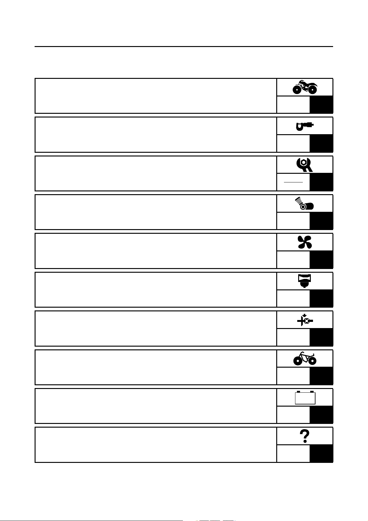
TABLE OF CONTENTS
GENERAL INFORMATION
GEN
INFO
1
SPECIFICATIONS
SPEC
2
PERIODIC CHECKS AND
ADJUSTMENTS
CHK
ADJ
3
ENGINE
ENG
4
COOLING SYSTEM
COOL
5
CARBURETION
CARB
6
DRIVE TRAIN
DRIV
7
CHASSIS
CHAS
8
ELECTRICAL
ELEC
9
TROUBLESHOOTING
TRBL
SHTG
10
– +


GEN
INFO
1

GEN
INFO
CHAPTER 1.
GENERAL INFORMATION
MACHINE IDENTIFICATION
........................................................................ 1-1
VEHICLE IDENTIFICATION NUMBER ................................................. 1-1
MODEL LABEL ..................................................................................... 1-1
FEATURES
................................................................................................... 1-2
LIQUID COOLING ENGINE .................................................................. 1-2
PARK POSITION .................................................................................. 1-2
FRONT DIFFERENTIAL ....................................................................... 1-3
IMPORTANT INFORMATION
...................................................................... 1-8
PREPARATION FOR REMOVAL PROCEDURES ............................... 1-8
REPLACEMENT PARTS ...................................................................... 1-8
GASKETS, OIL SEALS AND O-RINGS ................................................ 1-8
LOCK WASHERS/PLATES AND COTTER PINS ................................. 1-9
BEARINGS AND OIL SEALS ................................................................ 1-9
CIRCLIPS .............................................................................................. 1-9
CHECKING OF CONNECTIONS
............................................................... 1-10
SPECIAL TOOLS
....................................................................................... 1-11

GEN
INFO
1 - 1
GEN
INFO
MACHINE IDENTIFICATION
GENERAL INFORMATION
MACHINE IDENTIFICATION
VEHICLE IDENTIFICATION NUMBER
The vehicle identification number 1 is
stamped into the left side of the frame.
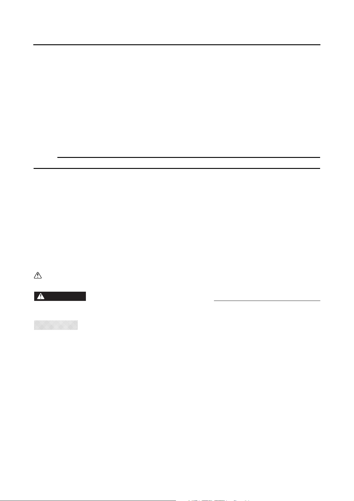
MODEL LABEL
The model label 1 is affixed to the frame. This
information will be needed to order spare
parts.
1 - 2
GEN
INFO
FEATURES
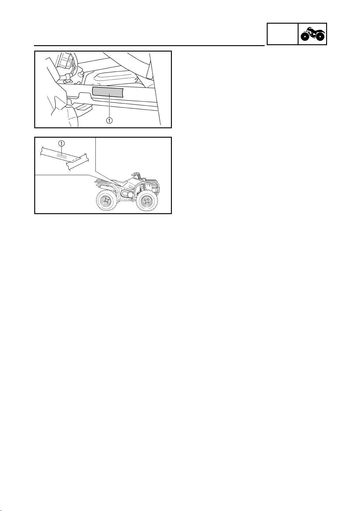
LIQUID COOLING ENGINE
Compact liquid cooled 45° inclined engine. A
liquid cooling system has been incorporated
for stable power and engine endurance.
1
Radiator
2
Thermo switch
3
Fan motor
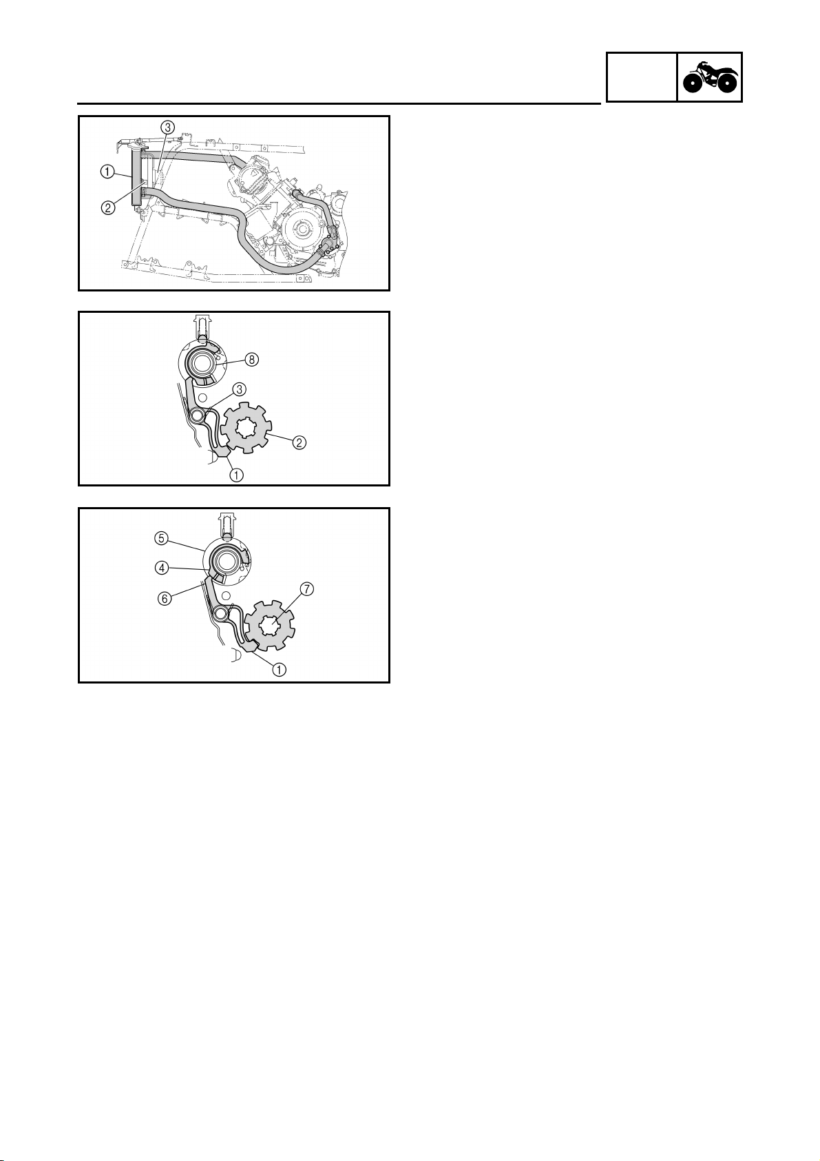
PARK POSITION
When the drive select lever is shifted into the
park position, a stopper lever is engaged into
the stopper gear preventing the drive select
lever and transmission from moving.
When the drive select lever is at the “L”, “H”,
“N”, or “R” positions, the stopper lever end
1
is moved away from the stopper gear
2
by the
return spring
3
.
When the drive select lever is in the “P”
position, the lever cam
4
at the side of the
shift cam
5
lifts the stopper lever end
6
and
the stopper lever end locks the drive axle
7
.
When the stopper lever end
1
is not
synchronized, a torsion spring
8
retains the
rotation force of the shift cam
5
until it is
synchronized.
FEATURES
GEN
INFO
1 - 3
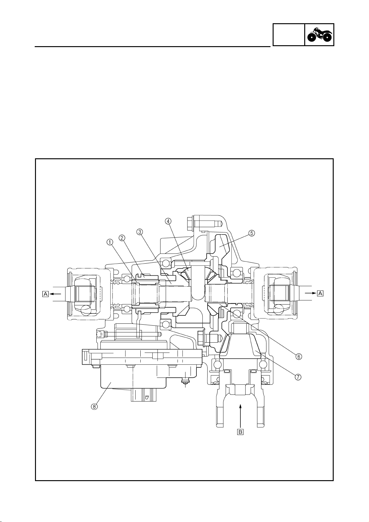
FEATURES
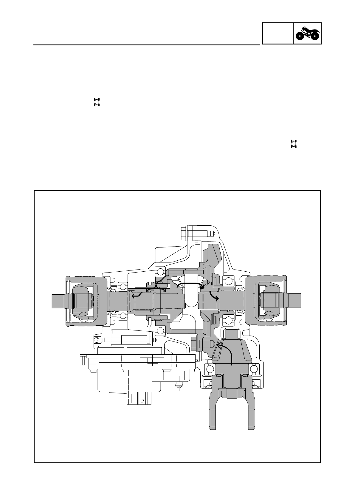
FRONT DIFFERENTIAL
1 Adapter
2 Drive clutch
3 Differential side gear (left)
4 Differential pinion gear
5 Ring gear
6 Differential side gear (right)
7 Drive pinion gear
8 Gear motor
È To front wheel
É From the middle gear
GEN
INFO
1 - 4
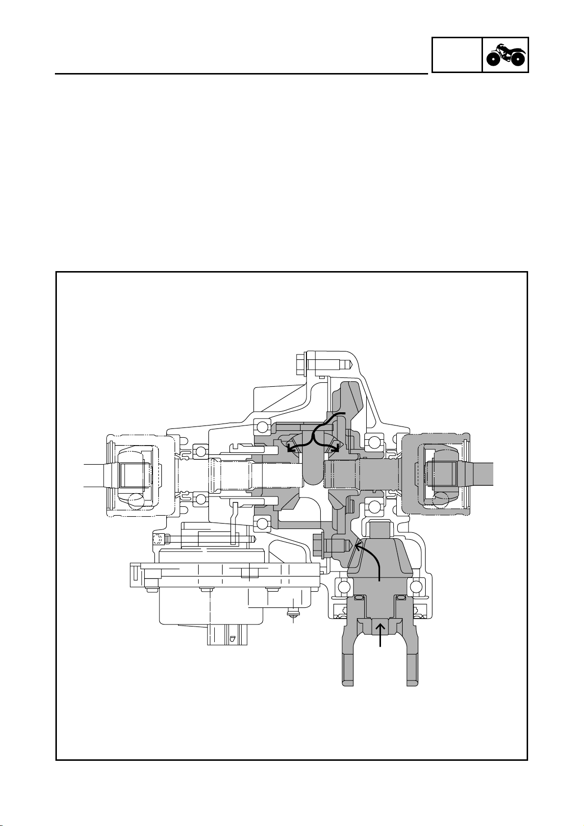
FEATURES
2WD
Power is transmitted as follows: middle gear → front drive shaft → drive pinion gear 7 → ring gear
5 → differential pinion gear 4. In the 2WD mode, the left differential side gear 3 and the drive
clutch 2 are not engaged, therefore, the left side gear runs idle and does not transmit power to the
left front constant velocity joint.
GEN
INFO
1 - 5
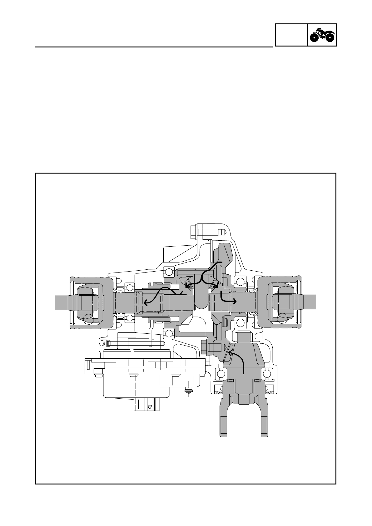
FEATURES
4WD
When the 4WD mode is selected, the gear motor is operated, and the drive clutch 2 moves to the
right and engages with the left differential side gear 3. Accordingly, power is transmitted as follows:
ring gear 5 → differential pinion gear 4 → left differential side gear 3 → drive clutch 2 → adapter
1 → left front constant velocity joint.
Meanwhile, power from the differential pinion gear 4 is transmitted to the right front constant
velocity joint via the right differential side gear 6.
The ring gear 5 and the drive clutch 2 are not engaged at this time. Therefore, the rotational
difference that occurs between the right and left wheels, while the handlebar is being turned, is
absorbed by the difference in the rotational speeds of the ring gear 5 and the left differential side
gear 3.
GEN
INFO
1 - 6
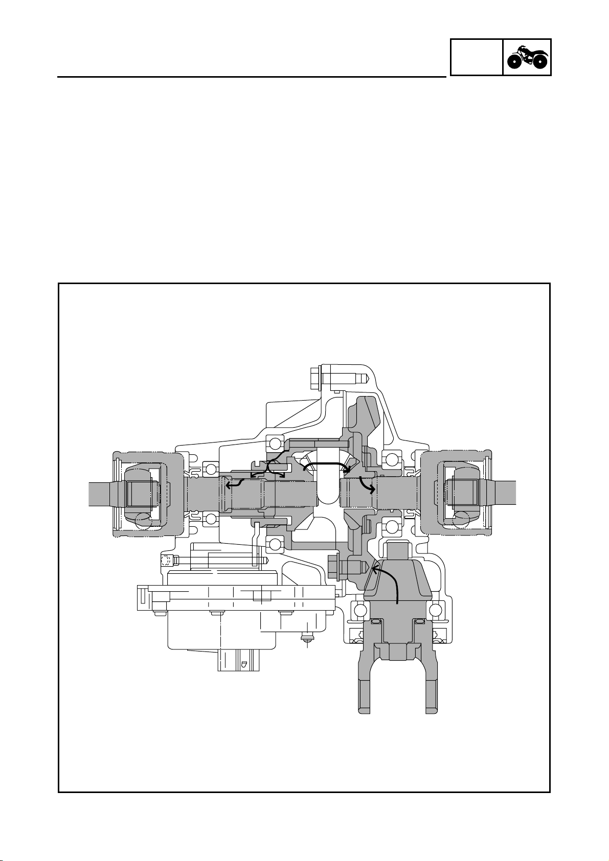
FEATURES
4WD (Diff-Lock)
When the 4WD (Diff-Lock) mode is selected, the gear motor moves the drive clutch 2 further to the
right, which causes the ring gear 5 and the drive clutch 2 to engage. As a result, power is
transmitted directly from the ring gear 5 to the drive clutch 2, then to the left front constant velocity
joint via the adapter 1.
Meanwhile, because the ring gear 5 and the drive clutch 2 are engaged, the ring gear 5, the drive
clutch 2, and the right differential side gear 6 become locked coaxially. Thus, power is transmitted
as follows: differential pinion gear 4 → right differential pinion gear 6 → right front constant
velocity joint.
When the ATV is in the 4WD (Diff-Lock) mode, the right and left wheels rotate constantly at the
same speed, which affects the maneuverability of the ATV (e.g., making it difficult to steer).
Therefore, the maximum traveling speed is limited to 35 km/h (22 mph).
GEN
INFO
1 - 7
FEATURES
In addition, the 4WD (Diff-Lock) mode can be engaged only when the ATV is stopped. Even if an
attempt is made to select this mode when the ATV is traveling, it will only result in a standby
condition (i.e., when the differential lock select switch and the differential gear are not matched).
(1) When the ATV is traveling
Even if the 4WD (Diff-Lock) mode is selected, the gear motor will stand by, instead of operating.
Therefore, the ATV can be driven in the normal 4WD mode. When this occurs, the differential gear
lock indicator light “” in the speedometer unit will flash to alert the driver that the control is on
standby. When the ATV is stopped, the control transfers to the condition described in (2).
(2) When the ATV is stopped
The gear motor operates to connect the drive clutch to the differential case, thus resulting in the
differential lock condition. When this occurs, the differential gear lock indicator light “” in the
speedometer unit changes to a constant illumination.
* Until the drive clutch and the differential case mesh together (i.e., the splines are unmeshed) the
engine misfires to control the engine speed. During this time, the differential gear lock indicator light
in the speedometer unit continues to flash.
DIFF.
LOCK
DIFF.
LOCK

1 - 8
GEN
INFO
EB101000
IMPORTANT INFORMATION
PREPARATION FOR REMOVAL
PROCEDURES
1.Remove all dirt, mud, dust and foreign
material before removal and disassembly.
2.Use proper tools and cleaning equipment.
Refer to the “SPECIAL TOOLS” section.
3.When disassembling the machine, always
keep mated parts together. This includes
gears, cylinder, piston and other parts that
have been “mated” through normal wear.
Mated parts must always be reused or
replaced as an assembly.
4.During machine disassembly, clean all parts
and place them in trays in the order of
disassembly. This will speed up assembly
and allow for the correct installation of all
parts.
5.Keep all parts away from any source of fire.
EB101010
REPLACEMENT PARTS
1.Use only genuine Yamaha parts for all
replacements. Use oil and grease
recommended by Yamaha for all lubrication
jobs. Other brands may be similar in function
and appearance, but inferior in quality.
EB101020
GASKETS, OIL SEALS AND O-RINGS
1.Replace all gaskets, seals and O-rings when
overhauling the engine. All gasket surfaces,
oil seal lips and O-rings must be cleaned.
2.Properly oil all mating parts and bearings
during reassembly. Apply grease to the oil
seal lips.
IMPORTANT INFORMATION
1 - 9
GEN
INFO
EB101030
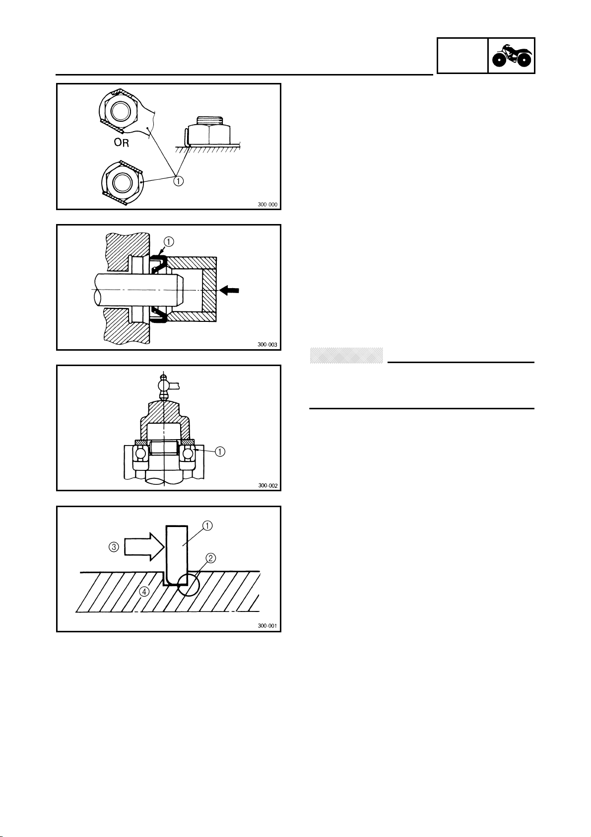
LOCK WASHERS/PLATES AND COTTER
PINS
1.Replace all lock washers/plates
1
and cotter
pins after removal. Bend lock tabs along the
bolt or nut flats after the bolt or nut has been
tightened to specification.
EB101040
BEARINGS AND OIL SEALS
1.Install bearings and oil seals so that the
manufacturer’s marks or numbers are visible.
When installing oil seals, apply a light
coating of lightweight lithium base grease to
the seal lips. Oil bearings liberally when
installing, if appropriate.
1
Oil seal
CAUTION:
Do not use compressed air to spin the
bearings dry. This will damage the bearing
surfaces.
1
Bearing
EB101050
CIRCLIPS
1.Check all circlips carefully before
reassembly. Always replace piston pin clips
after one use. Replace distorted circlips.
When installing a circlip
1
, make sure that
the sharp-edged corner
2
is positioned
opposite the thrust
3
it receives. See
sectional view.
4
Shaft
IMPORTANT INFORMATION
1 - 10
GEN
INFO
CHECKING OF CONNECTIONS
EB801000
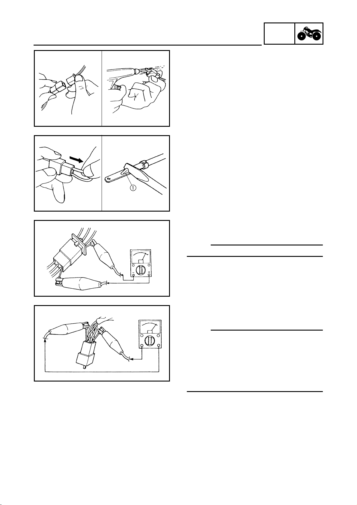
CHECKING OF CONNECTIONS
Check the connectors for stains, rust,
moisture, etc.
1.Disconnect:
●
Connector
2.Check:
●
Connector
Moisture
→
Dry each terminal with an air
blower.
Stains/rust
→
Connect and disconnect the
terminals several times.
3.Check:
●
Connector leads
Looseness
→
Bend up the pin
1
and
connect the terminals.
4.Connect:
●
Connector terminals
OTE:
The two terminals “click” together.
5.Check:
●
Continuity (using a pocket tester)
OTE:
●
If there is no continuity, clean the terminals.
●
When checking the wire harness be sure to
perform steps 1 to 3.
●
As a quick remedy, use a contact revitalizer
available at most part stores.
●
Check the connector with a pocket tester as
shown.
GEN
INFO
1 - 11
SPECIAL TOOLS
EB102001
SPECIAL TOOLS
The following special tools are necessary for complete and accurate tune-up and assembly. Use
only the appropriate special tools; this will help prevent damage caused by the use of inappropriate
tools or improvised techniques. Special tools may differ by shape and part number from country to
country. In such a case, two types are provided.
When placing an order, refer to the list provided below to avoid any mistakes.
For US and CDN
P/N. YM-, YU-, YS-, YK-, ACC-
Except for US and CDN
P/N. 90890-
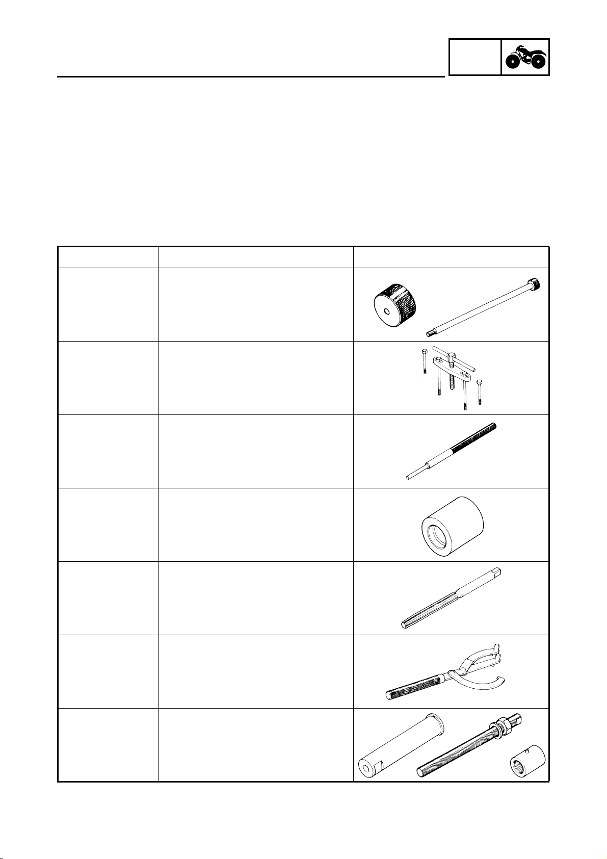
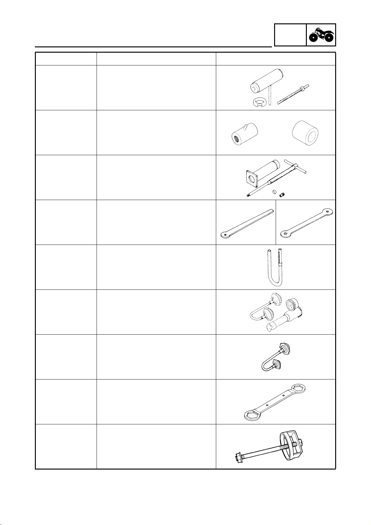
Tool No. Tool name/How to use Illustration
Bolt
90890-01083
Weight
90890-01084
Set
YU-01083-A
Slide hammer bolt (M6)/weight/set
These tools are used to remove the
rocker arm shaft.
90890-01135
YU-01135-A
Crankcase separating tool
This tool is used to separate the
crankcase.
90890-01225
YM-01225-A
Valve guide remover (7.0 mm)
This tool is needed to remove and
install the valve guide.
90890-04017
YM-04017
Valve guide installer (7.0 mm)
This tool is needed to install the valve
guide.
90890-01227
YM-01227
Valve guide reamer (7.0 mm)
This tool is needed to rebore the new
valve guide.
90890-01235
YU-01235
Rotor holding tool
This tool is needed to hold the starter
pulley when removing/installing the
starter pulley bolt or camshaft
sprocket bolts.
90890-04088
Bolt
90890-01275
Buffer boss installer set
Crankshaft installer bolt
These tools are used to install the
crankshaft.
GEN
INFO
1 - 12
SPECIAL TOOLS
YU-90050
Crankshaft installer set
These tools are used to install the
crankshaft.
Adapter
YM-33279
Spacer
90890-04060
YM-90070-A
Adapter (#11)
Spacer (crankshaft)
These tools are used to install the
crankshaft.
90890-01304
YU-01304
Piston pin puller set
This tool is used to remove the piston
pin.
90890-01311
YU-08035
Tappet adjusting tool (3 mm)
This tool is necessary for adjusting
the valve clearance.
90890-01312
YM-01312-A
Fuel level gauge
This gauge is used to measure the
fuel level in the float chamber.
90890-01325
YU-24460-01
Radiator cap tester
This tool is used to check the cooling
system.
90890-01352
YU-33984
Adapter
This tool is used to check the cooling
system.
90890-01348
Locknut wrench
This tool is needed when removing or
installing the secondary sheave
spring.
90890-04134
YM-04134
Sheave spring compressor
This tool is needed when removing or
installing the secondary sheave
spring.
Tool No. Tool name/How to use Illustration

GEN
INFO
1 - 13
SPECIAL TOOLS
90890-04135
YM-04135
Sheave fixed block
This tool is needed when removing or
installing the secondary sheave
spring.
90890-01404
YM-01404
Flywheel puller
These tools are needed to remove
the rotor.
90890-01327
YM-01327
Damper rod holder (30 mm)
This tool is needed to loosen and
tighten the steering stem bearing
retainer.
90890-01426
YU-38411
Oil filter wrench
This tool is needed to loosen or
tighten the oil filter cartridge.
90890-01430
YM-38404
Ring nut wrench
This tool is needed to removing and
installing the middle driven shaft
bearing retainer.
90890-01467
YM-01467
90890-01475
YM-01475
Gear lash measurement tool
This tool is used to measure the gear
lash.
90890-01474
YM-01474
Ball joint remover/installer set
This tool is used to remove and install
the ball joint.
YM-01477
Ball joint remover/installer attachment
set
This tool is used to remove and install
the ball joint.
90890-01701
YU-01880
Sheave holder
This tool is needed to hold the
primary sheave when removing or
installing the sheave bolts.
Tool No. Tool name/How to use Illustration
GEN
INFO
1 - 14
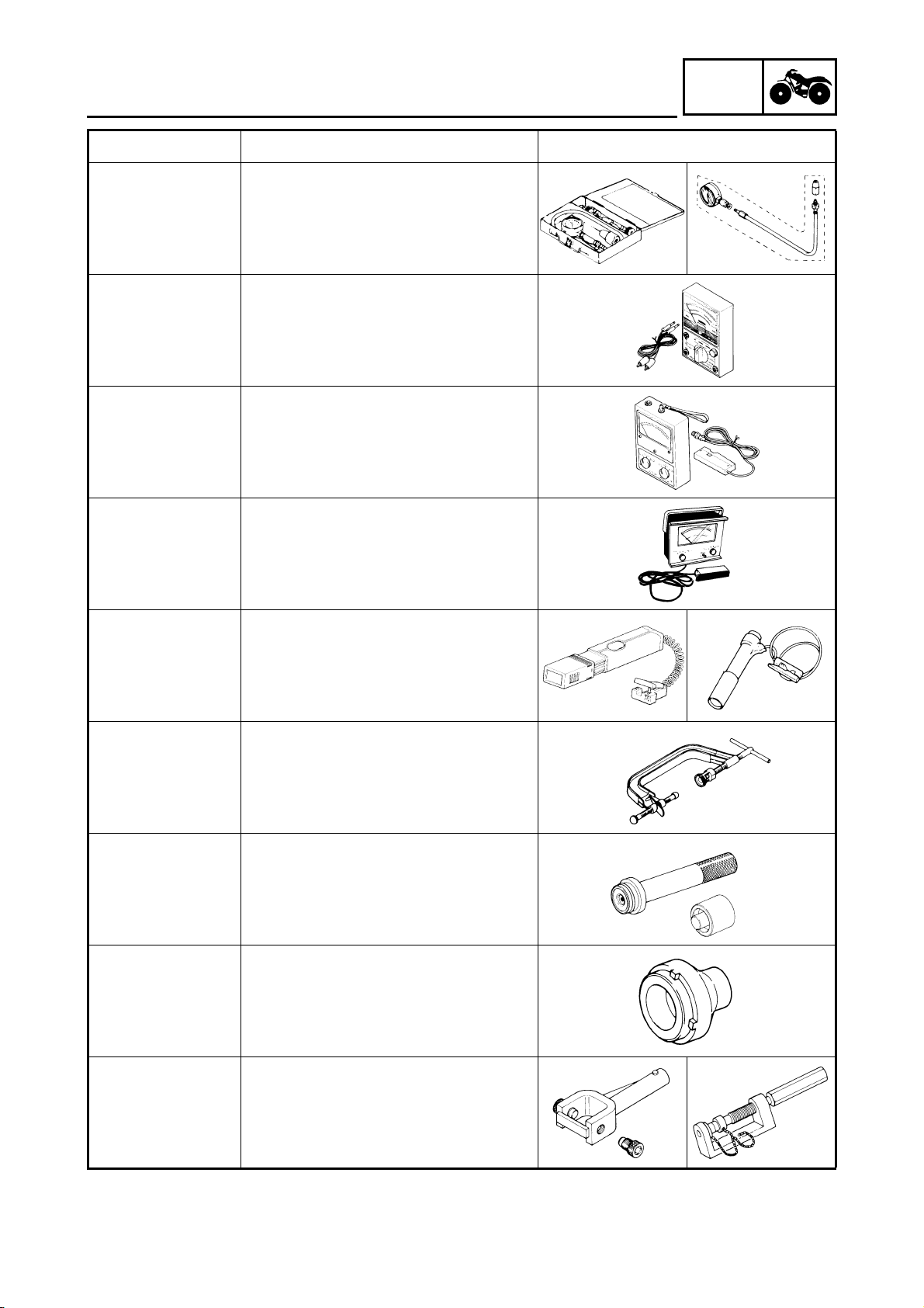
SPECIAL TOOLS
Compression gauge
90890-03081
YU-33223
Adapter
90890-04082
YU-33223-3
Compression gauge
Adapter
These tools are needed to measure
engine compression.
90890-03112
YU-03112
Pocket tester
This instrument is needed for
checking the electrical system.
90890-03113
Engine tachometer
This tool is needed for observing
engine rpm.
YU-8036-A
Inductive tachometer
This tool is needed for observing
engine rpm.
90890-03141
YM-33277-A
Timing light
This tool is necessary for checking
ignition timing.
90890-04019
YM-04019
Valve spring compressor
This tool is needed to remove and
install the valve assemblies.
Middle driven shaft
bearing driver
90890-04058
YM-04058-1
Mechanical seal installer
90890-04078
YM-33221
Middle driven shaft bearing driver
Mechanical seal installer
These tools are used to install the
water pump seal.
90890-04050
YM-04050
Bearing retainer wrench
This tool is needed when removing or
installing the final drive shaft bearing
retainer.
90890-04062
YM-04062
Universal joint holder
This tool is needed when removing or
installing the universal joint yoke nut.
Tool No. Tool name/How to use Illustration
GEN
INFO
1 - 15
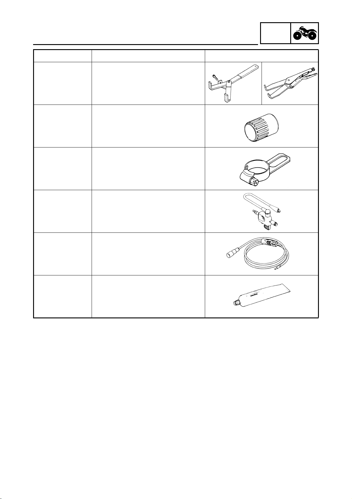
SPECIAL TOOLS
90890-04086
YM-91042
Clutch holding tool
This tool is needed to hold the clutch
carrier when removing or installing
the carrier nut.
90890-04128
YM-04128
Bearing retainer wrench
This tool is needed when removing or
installing the middle driven pinion
gear bearing retainer.
90890-04129
YM-04129
Pinion gear fix clamp
This tool is used to hold the shift cam.
90890-06754
Ignition checker
This instrument is necessary for
checking the ignition system
components.
YM-34487
Dynamic spark tester
This instrument is necessary for
checking the ignition system
components.
Bond
90890-85505
Sealant
ACC-11001-05-01
Yamaha bond No. 1215
Sealant (Quick Gasket
®
)
This sealant (bond) is used on
crankcase mating surfaces, etc.
Tool No. Tool name/How to use Illustration

SPEC
2

SPEC
CHAPTER 2.
SPECIFICATIONS
GENERAL SPECIFICATIONS
..................................................................... 2-1
MAINTENANCE SPECIFICATIONS
............................................................ 2-4
ENGINE ................................................................................................. 2-4
CHASSIS ............................................................................................. 2-14
ELECTRICAL ...................................................................................... 2-18
HOW TO USE THE CONVERSION TABLE
............................................... 2-20
GENERAL TORQUE SPECIFICATIONS
................................................... 2-20
LUBRICATION POINTS AND LUBRICANT TYPES
................................. 2-21
ENGINE ............................................................................................... 2-21
COOLANT FLOW DIAGRAMS
.................................................................. 2-22
OIL FLOW DIAGRAMS
.............................................................................. 2-24
CABLE ROUTING
...................................................................................... 2-27

SPEC
Loading...