


EAU00000
INTRODUCTION
Congratulations on your purchase of the Yamaha SCORPIO. This model is the result of Yamaha’s vast experience in the production of fine sporting, touring, and pacesetting racing machines. It represents the high degree of craftsmanship and reliability that have made Yamaha a leader in these fields.
This manual will give you an understanding of the operation, inspection, and basic maintenance of this motorcycle. If you have any questions concerning the operation or maintenance of your motorcycle, please consult a Yamaha dealer.
EAU03337*
SCORPIO
OWNER’S MANUAL ©2006 by Yamaha Motor Co., Ltd.
1st Edition, April 2006 All rights reserved.
Any reprinting or unauthorized use without the written permission of Yamaha Motor Co., Ltd.
is expressly prohibited. Printed in Indonesia.

EAU00005
IMPORTANT MANUAL INFORMATION
Particularly important information is distinguished in this manual by the following notations:
QThe Safety Alert Symbol means ATTENTION! BECOME ALERT! YOUR SAFETY IS INVOLVED!
wFailure to follow WARNING instructions could result in severe injury or death to the motorcycle operator, a bystander, or a person inspecting or repairing the
motorcycle.
cC |
A CAUTION indicates special precautions that must be taken to avoid damage to |
|
the motorcycle. |
NOTE: A NOTE provides key information to make procedures easier or clearer.
NOTE:
8This manual should be considered a permanent part of this motorcycle and should remain with it even if the motorcycle is subsequently sold.
8Yamaha continually seeks advancements in product design and quality. Therefore, while this manual contains the most current product information available at the time of printing, there may be minor discrepancies between your motorcycle and this manual. If you have any questions concerning this manual, please consult your Yamaha dealer.
EW000002
w
PLEASE READ THIS MANUAL CAREFULLY AND COMPLETELY BEFORE OPERATING THIS MOTORCYCLE.

EAU00009
TABLE OF CONTENTS
1 |
...............GIVE SAFETY THE RIGHT OF WAY |
1-1 |
4 |
............................PRE-OPERATION CHECKS |
4-1 |
|
|
|
|
.................................Pre-operation check list |
4-1 |
2 |
..................................................DESCRIPTION |
2-1 |
|
|
.........................................................Left view |
2-1 |
|
|
Right view ...................................................... |
2-2 |
|
|
Controls and instruments ............................... |
2-3 |
|
|
INSTRUMENT AND CONTROL |
|
|
3 |
|
||
FUNCTIONS |
3-1 |
||
|
|||
|
Main switch/steering lock ............................... |
3-1 |
|
|
Indicator lights ................................................ |
3-2 |
|
|
Speedometer unit .......................................... |
3-2 |
|
|
Tachometer .................................................... |
3-3 |
|
|
Fuel gauge ..................................................... |
3-3 |
|
|
Handlebar switches ........................................ |
3-3 |
|
|
Clutch lever .................................................... |
3-5 |
|
|
Shift pedal ...................................................... |
3-5 |
|
|
Brake lever ..................................................... |
3-5 |
|
|
Brake pedal .................................................... |
3-6 |
|
|
Fuel tank cap ................................................. |
3-6 |
|
|
Fuel ................................................................ |
3-7 |
|
|
Fuel cock ........................................................ |
3-7 |
|
|
Starter (choke) lever ...................................... |
3-8 |
|
|
Kickstarter ...................................................... |
3-9 |
|
|
Seat ................................................................ |
3-9 |
|
|
Helmet holder ............................................... |
3-10 |
5 |
OPERATION AND IMPORTANT |
|
|
RIDING POINTS ............................................... |
5-1 |
||
|
|||
|
Starting and warming up a cold engine .......... |
5-1 |
|
|
Starting a warm engine .................................. |
5-2 |
|
|
Shifting ........................................................... |
5-3 |
|
|
Tips for reducing fuel consumption ............... |
5-3 |
|
|
Engine break-in .............................................. |
5-4 |
|
|
Parking ........................................................... |
5-5 |
|
|
GENERAL NOTE............................................ |
5-6 |
|
|
PERIODIC MAINTENANCE AND |
|
|
6 |
|
||
MINOR REPAIR ................................................ |
6-1 |
||
|
|||
|
Owner’s tool kit .............................................. |
6-1 |
|
|
Periodic maintenance and lubrication chart ... |
6-2 |
|
|
Checking the spark plug ................................ |
6-6 |
|
|
Engine oil and oil filter element ..................... |
6-7 |
|
|
Cleaning the air filter element and |
|
|
|
check hose ................................................. |
6-10 |
|
|
Adjusting the carburetor ............................... |
6-12 |
|
|
Adjusting the engine idling speed ................ |
6-12 |
|
|
Adjusting the throttle cable free play ............ |
6-13 |
|
|
Adjusting the valve clearance ...................... |
6-14 |
|
|
Tires ............................................................. |
6-14 |

TABLE OF CONTENTS
Spoke wheels ............................................... |
6-16 |
Adjusting the clutch lever free play .............. |
6-17 |
Adjusting the brake lever free play ............... |
6-18 |
Adjusting the brake pedal position and |
|
free play ..................................................... |
6-18 |
Checking the front brake pads and |
|
rear brake shoes ........................................ |
6-20 |
Adjusting the rear brake light switch ............ |
6-20 |
Checking the brake fluid level ...................... |
6-21 |
Changing the brake fluid .............................. |
6-22 |
Drive chain slack .......................................... |
6-23 |
Lubricating the drive chain ........................... |
6-24 |
Checking and lubricating the cables ............ |
6-25 |
Checking and lubricating the throttle |
|
grip and cable ............................................ |
6-26 |
Checking and lubricating the brake and |
|
shift pedals ................................................. |
6-26 |
Checking and lubricating the centerstand |
|
and sidestand ............................................. |
6-27 |
Checking and lubricating the brake |
|
and clutch levers ........................................ |
6-27 |
Lubricating the rear suspension .................. |
6-28 |
Checking the front fork ................................. |
6-28 |
Checking the steering .................................. |
6-29 |
Checking the wheel bearings ....................... |
6-29 |
Battery .......................................................... |
6-30 |
|
Replacing the fuse ...................................... |
6-32 |
|
|
Replacing the headlight bulb ........................ |
6-33 |
|
|
Replacing a turn signal light bulb ................. |
6-34 |
|
|
Replacing the tail/brake light bulb ................ |
6-35 |
|
|
Troubleshooting ........................................... |
6-36 |
|
|
Troubleshooting chart .................................. |
6-37 |
|
|
MOTORCYCLE CARE AND STORAGE |
7-1 |
|
7 |
|||
A. CLEANING |
7-1 |
||
|
|||
|
B. STORAGE ................................................. |
7-1 |
|
|
SPECIFICATIONS |
8-1 |
|
8 |
|||
Specifications |
8-1 |
||
|
|||
|
CONSUMER INFORMATION |
9-1 |
|
9 |
|||
Identification numbers .................................... |
9-1 |
||
|
|||
|
Frame serial number ...................................... |
9-1 |
|
|
Engine serial number ..................................... |
9-1 |

EAU00021
Q GIVE SAFETY THE RIGHT OF WAY
Motorcycles are fascinating vehicles, which can give you an unsurpassed feeling of power and freedom. However, they also impose certain limits, which you must accept; even the best motorcycle
does not ignore the laws of physics.
1
Regular care and maintenance are essential for preserving value and operating condition of your motorcycle. Moreover, what is true for the motorcycle is also true for the rider: good performance depends on being in good shape. Riding under the influence of medication, drugs and alcohol is, of course, out of the question. Motorcycle riders—more than car drivers—must always be at their mental and physical best. Under the influence of even small amounts of alcohol, there is a tendency to take dangerous risks.
Protective clothing is as essential for the motorcycle rider as seat belts are for car drivers and passengers. Always wear a complete motorcycle suit (whether made of leather or tear-resistant synthetic materials with protectors), sturdy boots, motorcycle gloves and a properly fitting helmet. Optimum protective wear, however, should not encourage carelessness. Although full-coverage helmets and suits, in particular, create an illusion of total safety and protection, motorcyclists will always be vulnerable. Riders who lack critical self-control run the risk of going too fast and are apt to take chances. This is even more dangerous in wet weather. The good motorcyclist rides safely, predictably and defensively—avoiding all dangers, including those caused by others.
Enjoy your ride!
1-1

EAU00026
DESCRIPTION
Left view
1 |
2 |
3 |
2
6 |
5 |
4 |
1. |
Fuel cock |
(Page 3-7) |
4. |
Air filter element |
(Page 6-10) |
2. |
Owner’s tool kit |
(Page 6-1) |
5. |
Shift pedal |
(Page 3-5) |
3. |
Helmet holder |
(Page 3-10) |
6. |
Starter (choke) lever |
(Page 3-8) |
2-1

DESCRIPTION
Right view
7 8
2
|
|
12 |
11 |
10 |
9 |
|
7. |
Fuse |
(Page 6-32) |
10.Engine oil level check window |
(Page 6-8) |
||
8. |
Kickstarter |
(Page 3-9) |
|
11.Brake pedal |
(Page 3-6,6-18) |
|
9. |
Engine oil filter element |
(Page 6-8) |
|
12.Battery |
(Page 6-30) |
|
2-2

DESCRIPTION
Controls and instruments
1 |
2 |
3 |
4 |
5 |
6 |
7 |
2
9 8
1. |
Clutch lever |
(Page 3-5,6-17) |
6. |
Right handlebar switches |
(Page 3-4) |
2. |
Left handlebar switches |
(Page 3-3) |
7. |
Brake lever |
(Page 3-5,6-18) |
3. |
Speedometer unit |
(Page 3-2) |
8. |
Throttle grip |
(Page 6-13,6-26) |
4. |
Main switch/steering lock |
(Page 3-1) |
9. |
Fuek tank cap |
(Page 3-6) |
5. |
Tachometer/Fuel gauge |
(Page 3-3) |
|
|
|
2-3
EAU00027
INSTRUMENT AND CONTROL FUNCTIONS
ON
OFF
LOCK
EAU00029
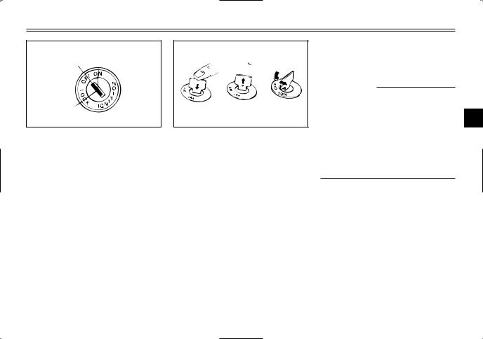
Main switch/steering lock
The main switch/steering lock controls the ignition and lighting systems, and is used to lock the steering. The various positions are described below.
ab c
c
a.Push.
b.Release.
c.Turn.
EAU00043
LOCK
The steering is locked, and all electrical systems are off. The key can be removed.
To unlock the steering
Insert the key and turn it to “OFF”.
EW000016
w
Never turn the key to “OFF” or “LOCK” while the motorcycle is moving, otherwise the electrical 3 systems will be switched off, which may result in loss of control
or an accident. Make sure that the motorcycle is stopped before turning the key to “OFF” or “LOCK”.
EAU00036
ON
All electrical systems are supplied with power, and the engine can be started. The key cannot be removed.
EAU00038
OFF
All electrical systems are off. The key can be removed.
To lock the steering
1.Turn the handlebars all the way to the left or right.
2.Push the key in from the “OFF” position, release it, and then turn it to “LOCK”.
3.Remove the key.
3-1

INSTRUMENT AND CONTROL FUNCTIONS
EAU00063 |
2 |
|
High beam indicator light “&” |
||
|
||
This indicator light comes on when |
1 |
|
the high beam of the headlight is |
|
|
switched on. |
|
4 |
3 |
1 |
2 |
3 |
1 |
3 |
1.Turn signal indicator light “5”
2.Neutral indicator light “N”
3.High beam indicator light “&”
EAU00056
Indicator lights
EAU04121
Turn signal indicator lights “4” and “6”
The corresponding indicator light flashes when the turn signal switch is pushed to the left or right.
EAU00061
Neutral indicator light “N”
This indicator light comes on when the transmission is in the neutral position.
1.Speedometer
2.Odometer
3.Tripmeter
4.Reset knob
EAU00095
Speedometer unit
The speedometer unit is equipped with a speedometer, an odometer and a tripmeter. The speedometer shows riding speed. The odometer shows the total distance traveled. The tripmeter shows the distance traveled since it was last set to zero with the reset knob. The tripmeter can be used to estimate the distance that can be traveled with a full tank of fuel. This information will enable you to plan future fuel stops.
3-2
INSTRUMENT AND CONTROL FUNCTIONS
3 1 |
2 |
1.Tachometer
2.Red zone
3.Fuel gauge
EAU00102
Tachometer
The tachometer allows the rider to monitor the engine speed and keep it within the ideal power range.
EC000003
cC
Do not operate the engine in the tachometer red zone.
Red zone: 9500 r/min and above
EAU00113
Fuel gauge
The fuel gauge indicates the amount of fuel in the fuel tank. The needle moves towards “E” (Empty) as the fuel level decreases. When the needle reaches “E”, refuel as soon as possible.
NOTE:
Do not allow the fuel tank to empty itself completely.
1 |
2 |
3 |
5 |
4 |
3 |
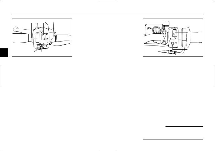
1.Light switch
2.Pass switch “&”
3.Dimmer switch
4.Turn signal switch
5.Horn switch “HORN”
EAU00118
Handlebar switches
EAU03898
Light switch “1/'/:”
Set this switch to “'” to turn on the auxiliary light, meter lighting and taillight. Set the switch to “:” to turn on the headlight also. Set the switch to “1” to turn off all the lights.
EAU00119
Pass switch “&”
Press this switch to flash the headlight.
3-3
INSTRUMENT AND CONTROL FUNCTIONS
|
1 |
2 |
3 |
3 |
5 |
|
4 |
EAU00130
Horn switch “HORN”
Press this switch to sound the horn.
1 |
2 |
1.Light switch
2.Pass switch “&”
3.Dimmer switch
4.Turn signal switch
5.Horn switch “HORN”
EAU03888
Dimmer switch “&/%”
Set this switch to “&” for the high beam and to “%” for the low beam.
EAU03889
Turn signal switch “4/6”
To signal a right-hand turn, push this switch to “6”. To signal a left-hand turn, push this switch to “4”. When released, the switch returns to the center position. To cancel the turn signal lights, push the switch in after it has returned to the center position.
1.Engine stop switch
2.Start switch
EAU03890
Engine stop switch “#/$”
Set this switch to “#” before starting the engine. Set this switch to “$” to stop the engine in case of an emergency, such as when the motorcycle overturns or when the throttle cable is stuck.
EAU00143
Start switch “,”
Push this switch to crank the engine with the starter.
EC000005
cC
See page 5–1 for starting instructions prior to starting the engine.
3-4

INSTRUMENT AND CONTROL FUNCTIONS
1
1. Clutch lever
EAU00155
Clutch lever
The clutch lever is located at the left handlebar grip. To disengage the clutch, pull the lever toward the handlebar grip. To engage the clutch, release the lever. The lever should be pulled rapidly and released slowly for smooth clutch operation.
5
4
3
2
N 
1
1
1. Shift pedal N. Neutral
EAU01215
Shift pedal
The shift pedal is located on the left side of the engine and is used in combination with the clutch lever when shifting the gears of the 5-speed constant-mesh transmission equipped on this motorcycle.
NOTE:
Use your toes or heel to shift up and your toes to shift down.
1
3
1. Brake lever
EAU00158
Brake lever
The brake lever is located at the right handlebar grip. To apply the front brake, pull the lever toward the handlebar grip.
3-5
INSTRUMENT AND CONTROL FUNCTIONS
1 |
3 |
1. Brake pedal
EAU00162
Brake pedal
The brake pedal is on the right side of the motorcycle. To apply the rear brake, press down on the brake pedal.
a
2 
1
1.Fuel tank cap
2.Alignment mark " v "
a. Unlock.
EAU13020
Fuel tank cap
To remove the fuel tank cap
Insert the key into the lock and turn it 1/4 turn clockwise. The lock will be released and the fuel tank cap can be removed.
To install the fuel tank cap
1.Insert the fuel tank cap into the tank opening with the key inserted in the lock and with the " v " mark facing forward.
2.Turn the key counterclockwise to the original position, and then remove it.
NOTE:
The fuel tank cap cannot be installed unless the key is in the lock. In addition, the key cannot be removed if the cap is not properly installed and locked.
EWA10130
w
Make sure that the fuel tank cap is properly installed before riding.
3-6
INSTRUMENT AND CONTROL FUNCTIONS
2 |
1 |
1.Filler tube
2.Fuel level
EAU03753
Fuel
Make sure that there is sufficient fuel in the tank. Fill the fuel tank to the bottom of the filler tube as shown.
EW000130
w
8Do not overfill the fuel tank, otherwise it may overflow when the fuel warms up and expands.
8Avoid spilling fuel on the hot engine.
EAU00185
cC
Immediately wipe off spilled fuel with a clean, dry, soft cloth, since fuel may deteriorate painted surfaces or plastic parts.
EAU00187
Recommended fuel: Regular gasoline Fuel tank capacity: Total amount:
12 L
Reserve amount: 3.0 L
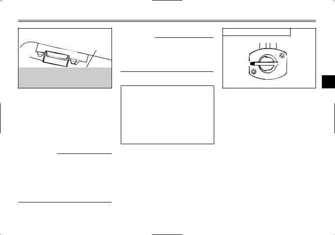
OFF: Closed position
RES
OFF 
FUEL
ON
3
EAU03050
Fuel cock
The fuel cock supplies fuel from the tank to the carburetor while filtering it also.
The fuel cock has three positions:
OFF
With the lever in this position, fuel will not flow. Always return the lever to this position when the engine is not running.
3-7

INSTRUMENT AND CONTROL FUNCTIONS
ON: Normal position
RES
OFF
FUEL
3 |
ON |
|
ON
With the lever in this position, fuel flows to the carburetor. Normal riding is done with the lever in this position.
RES: Reserve position |
RES |
RES |
OFF |
FUEL |
ON |
RES |
This indicates reserve. If you run out of fuel while riding, move the lever to this position. Fill the tank at the first opportunity. Be sure to set the lever back to “ON” after refueling!
1 |
b |
a |
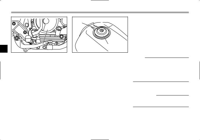
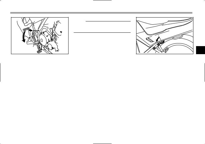
1. Starter (choke) lever “CHOKE”
EAU00211
Starter (choke) lever
Starting a cold engine requires a richer air-fuel mixture, which is supplied by the starter (choke).
Move the lever in direction a to turn on the starter (choke).
Move the lever in direction b to turn off the starter (choke).
3-8
INSTRUMENT AND CONTROL FUNCTIONS
1
2
1.Kickstarter
2.Footrest
EAU04217
Kickstarter
If the engine fails to start by pushing the start switch, try to start it by using the kickstarter.
To start the engine, fold out the kickstarter lever, move it down lightly with your foot until the gears engage, and then push it down smoothly but forcefully. This model is equipped with a primary kickstarter, allowing the engine to be started in any gear if the clutch is disengaged. However, shifting the transmission into the neutral position before starting is recommended.
NOTE:
Before using kick starter, fold in the footrest first.
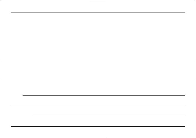
|
a |
|
3 |
a. |
Unlock. |
|
EAU01619* |
Seat |
|
To remove the seat
1.Insert the key into the seat lock, and then turn it counterclockwise.
2.Pull the seat off.
3-9

INSTRUMENT AND CONTROL FUNCTIONS
2 |
1 |
3 |
|
1.Projection
2.Seat holder
To install the seat
1.Insert the projection on the front of the seat into the seat holder as shown.
2.Push the rear of the seat down to lock it in place.
3.Remove the key.
NOTE:
Make sure that the seat is properly secured before riding.
1 |
1. Helmet holder
EAU00263
Helmet holder
The helmet holder is located under the seat.
To secure a helmet to the helmet holder
1.Remove the seat. (See page 3-9 for removal and installation procedures.)
2.Attach the helmet to the helmet holder, and then securely install the seat.
EW000030
w
Never ride with a helmet attached to the helmet holder, since the helmet may hit objects, causing loss of control and possibly an accident.
To release the helmet from the helmet holder
Remove the seat, remove the helmet from the helmet holder, and then install the seat.
3-10

EAU01114
PRE-OPERATION CHECKS
The condition of a vehicle is the owner’s responsibility. Vital components can start to deteriorate quickly and unexpectedly, even if the vehicle remains unused (for example, as a result of exposure to the elements). Any damage, fluid leakage or loss of tire air pressure could have serious consequences. Therefore, it is very important, in addition to a thorough visual inspection, to check the following points before each ride.
EAU03439
Pre-operation check list
ITEM |
CHECKS |
PAGE |
|
|
Fuel |
• Check fuel level in fuel tank. |
|
|
|
• Refuel if necessary. |
3-6–3-7 |
|
||
|
• Check fuel line for leakage. |
|
|
|
|
|
|
4 |
|
|
|
|
|
|
Engine oil |
• Check oil level in engine. |
|
|
|
• If necessary, add recommended oil to specified level. |
6-7–6-10 |
|
|
|
|
||||
|
• Check vehicle for oil leakage. |
|
|
|
|
|
|
|
|
|
• Check operation. |
|
|
|
|
• If soft or spongy, have Yamaha dealer bleed hydraulic system. |
|
|
|
Front brake |
• Check lever free play. |
|
|
|
• Adjust if necessary. |
3-5,6-18,6-21–6-22 |
|
||
|
• Check fluid level in reservoir. |
|
|
|
|
• If necessary, add recommended brake fluid to specified level. |
|
|
|
|
• Check hydraulic system for leakage. |
|
|
|
|
|
|
|
|
Rear brake |
• Check operation. |
|
|
|
• Check pedal free play. |
3-6,6-21–6-22 |
|
||
|
• Adjust if necessary. |
|
|
|
|
|
|
|
|
|
• Check operation. |
|
|
|
Clutch |
• Lubricate cable if necessary. |
3-5,6-17 |
|
|
• Check lever free play. |
|
|
||
|
|
|
|
|
|
• Adjust if necessary. |
|
|
|
|
|
|
|
|
|
• Make sure that operation is smooth. |
|
|
|
Throttle grip |
• Lubricate throttle grip, housing and cable if necessary. |
6-13,6-26 |
|
|
• Check free play. |
|
|
||
|
|
|
|
|
|
• Adjust if necessary. |
|
|
|
Control cables |
• Make sure that operation is smooth. |
6-25 |
|
|
• Lubricate if necessary. |
|
|
||
|
|
|
|
|
|
4-1 |
|
|
|
PRE-OPERATION CHECKS
|
|
ITEM |
CHECKS |
PAGE |
|
|
|
• Check chain slack. |
|
|
|
Drive chain |
• Adjust if necessary. |
6-23–6-25 |
|
|
• Check chain condition. |
||
|
|
|
|
|
|
|
|
• Lubricate if necessary. |
|
|
|
|
|
|
|
|
|
• Check for damage. |
|
|
|
Wheels and tires |
• Check tire condition and tread depth. |
6-14–6-16 |
|
|
• Check air pressure. |
|
|
|
|
|
|
|
|
|
|
• Correct if necessary. |
|
|
|
|
|
|
|
|
Brake and shift pedals |
• Make sure that operation is smooth. |
6-26 |
|
|
• Lubricate pedal pivoting points if necessary. |
||
|
|
|
|
|
|
|
|
|
|
4 |
|
Brake and clutch levers |
• Make sure that operation is smooth. |
6-27 |
|
• Lubricate lever pivoting points if necessary. |
|||
|
|
|
|
|
|
|
Centerstand, sidestand |
• Make sure that operation is smooth. |
6-27 |
|
|
• Lubricate pivots if necessary. |
||
|
|
|
|
|
|
|
|
|
|
|
|
Chassis fasteners |
• Make sure that all nuts, bolts and screws are properly tightened. |
— |
|
|
• Tighten if necessary. |
||
|
|
|
|
|
|
|
|
|
|
|
|
Instruments, lights, signals |
• Check operation. |
3-2–3-4,6-33–6-35 |
|
|
and switches |
• Correct if necessary. |
|
|
|
|
||
|
|
|
|
|
|
|
Battery |
• Check fluid level. |
6-30–6-32 |
|
|
• Fill with distilled water if necessary. |
||
|
|
|
|
|
|
|
|
|
|
NOTE:
Pre-operation checks should be made each time the motorcycle is used. Such an inspection can be accomplished in a very short time; and the added safety it assures is more than worth the time involved.
EWA00033
w
If any item in the Pre-operation check list is not working properly, have it inspected and repaired before operating the motorcycle.
4-2
EAU00372
OPERATION AND IMPORTANT RIDING POINTS
EAU00373
w
8Become thoroughly familiar with all operating controls and their functions before riding. Consult a Yamaha dealer regarding any control or function that you do not thoroughly understand.
8Never start the engine or operate it in a closed area for any length of time. Exhaust fumes are poisonous, and inhaling them can cause loss of consciousness and death within a short time. Always make sure that there is adequate ventilation.
8Before starting out, make sure that the sidestand is up. If the sidestand is not raised completely, it could contact the ground and distract the operator, resulting in a possible loss of control.
RES
OFF
FUEL
ON
EAU00411*
Starting and warming up a cold engine
1.Turn the fuel cock lever to “ON”.
2.Turn the key to “ON” and make sure that the engine stop switch is set to “#”.
3.Shift the transmission into the neutral position.
NOTE:
When the transmission is in the neutral position, the neutral indicator light should be on, otherwise have a Yamaha dealer check the electrical circuit.
1 |
1.Starter (choke) lever “CHOKE”
4.Turn the starter (choke) on and
completely close the throttle. 5 (See page 3-8 for starter (choke)
operation.)
5.Start the engine by pushing the start switch or by pushing the kickstarter lever down.
5-1

OPERATION AND IMPORTANT RIDING POINTS
NOTE:
If the engine fails to start by pushing the start switch, release the switch, wait a few seconds, and then try again. Each starting attempt should be as short as possible to preserve the battery. Do not crank the engine more than 10 seconds on any one attempt. If the engine does not start with the starter motor, try using the
kickstarter.
5
6.After starting the engine, move the starter (choke) lever back halfway.
ECA00055
cC
For maximum engine life, always warm the engine up before starting off. Never accelerate hard when the engine is cold!
7.When the engine is warm, turn the starter (choke) off.
NOTE:
The engine is warm when it responds normally to the throttle with the starter (choke) turned off.
EAU01258
Starting a warm engine
Follow the same procedure as for starting a cold engine with the exception that the starter (choke) is not required when the engine is warm.
5-2
 Loading...