


OWNER’S MANUAL

SPECIAL MESSAGE SECTION
This product utilizes batteries or an external power supply (adapter). DO NOT connect this product to any power supply or adapter other than one described in the manual, on the name plate, or specifically recommended by Yamaha.
WARNING:
Do not place this product in a position where anyone could walk on, trip over, or roll anything over power or connecting cords of any kind. The use of an extension cord is not recommended! IF you must use an extension cord, the minimum wire size for a 25' cord (or less ) is 18 AWG. NOTE: The smaller the AWG number ,the larger the current handling capacity. For longer extension cords, consult a local electrician.
This product should be used only with the components supplied or; a cart, rack, or stand that is recommended by Yamaha. If a cart, etc., is used, please observe all safety markings and instructions that accompany the accessory product.
SPECIFICATIONS SUBJECT TO CHANGE:
The information contained in this manual is believed to be correct at the time of printing. However, Yamaha reserves the right to change or modify any of the specifications without notice or obligation to update existing units.
This product, either alone or in combination with an amplifier and headphones or speaker/s, may be capable of producing sound levels that could cause permanent hearing loss. DO NOT operate for long periods of time at a high volume level or at a level that is uncomfortable. If you experience any hearing loss or ringing in the ears, you should consult an audiologist.
IMPORTANT: The louder the sound, the shorter the time period before damage occurs.
Some Yamaha products may have benches and / or accessory mounting fixtures that are either supplied with the product or as optional accessories. Some of these items are designed to be dealer assembled or installed. Please make sure that benches are stable and any optional fixtures (where applicable) are well secured BEFORE using.
Benches supplied by Yamaha are designed for seating only. No other uses are recommended.
NOTICE:
Service charges incurred due to a lack of knowledge relating to how a function or effect works (when the unit is operating as designed) are not covered by the manufacturer’s warranty, and are therefore the owners responsibility. Please study this manual carefully and consult your dealer before requesting service.
ENVIRONMENTAL ISSUES:
Yamaha strives to produce products that are both user safe and environmentally friendly. We sincerely believe that our products and the production methods used to produce them, meet these goals. In keeping with both the letter and the spirit of the law, we want you to be aware of the following:
Battery Notice:
This product MAY contain a small non-rechargeable battery which (if applicable) is soldered in place. The average life span of this type of battery is approximately five years. When replacement becomes necessary, contact a qualified service representative to perform the replacement.
This product may also use “household” type batteries. Some of these may be rechargeable. Make sure that the battery being charged is a rechargeable type and that the charger is intended for the battery being charged.
When installing batteries, do not mix batteries with new, or with batteries of a different type. Batteries MUST be installed correctly. Mismatches or incorrect installation may result in overheating and battery case rupture.
Warning:
Do not attempt to disassemble, or incinerate any battery. Keep all batteries away from children. Dispose of used batteries promptly and as regulated by the laws in your area. Note: Check with any retailer of household type batteries in your area for battery disposal information.
Disposal Notice:
Should this product become damaged beyond repair, or for some reason its useful life is considered to be at an end, please observe all local, state, and federal regulations that relate to the disposal of products that contain lead, batteries, plastics, etc. If your dealer is unable to assist you, please contact Yamaha directly.
NAME PLATE LOCATION:
The name plate is located on the bottom of the product. The model number, serial number, power requirements, etc., are located on this plate. You should record the model number, serial number, and the date of purchase in the spaces provided below and retain this manual as a permanent record of your purchase.
Model
Serial No.
Purchase Date
PLEASE KEEP THIS MANUAL
92-BP (bottom)

PRECAUTIONS
PLEASE READ CAREFULLY BEFORE PROCEEDING
* Please keep these precautions in a safe place for future reference.
 WARNING
Always follow the basic precautions listed below to avoid the possibility of serious injury or even death from electrical shock, short-circuiting, damages, fire or other hazards. These precautions include, but are not limited to, the following:
•Do not open the instrument or attempt to disassemble the internal parts or modify them in any way. The instrument contains no user-serviceable parts. If it should appear to be malfunctioning, discontinue use immediately and have it inspected by qualified Yamaha service personnel.
•Do not expose the instrument to rain, use it near water or in damp or wet conditions, or place containers on it containing liquids which might spill into any openings.
•If the AC adaptor cord or plug becomes frayed or damaged, or if there is a sudden loss of sound during use of the instrument, or if any unusual smells or smoke should appear to be caused by it, immediately turn off the power switch,
disconnect the adaptor plug from the outlet, and have the instrument inspected by qualified Yamaha service personnel.
•Use the specified adaptor (PA-3C or an equivalent recommended by Yamaha) only. Using the wrong adaptor can result in damage to the instrument or overheating.
•Before cleaning the instrument, always remove the electric plug from the outlet. Never insert or remove an electric plug with wet hands.
•Check the electric plug periodically and remove any dirt or dust which may have accumulated on it.
 CAUTION
Always follow the basic precautions listed below to avoid the possibility of physical injury to you or others, or damage to the instrument or other property. These precautions include, but are not limited to, the following:
•Do not place the AC adaptor cord near heat sources such as heaters or radiators, and do not excessively bend or otherwise damage the cord, place heavy objects on it, or place it in a position where anyone could walk on, trip over, or roll anything over it.
•When removing the electric plug from the instrument or an outlet, always hold the plug itself and not the cord.
•Do not connect the instrument to an electrical outlet using a multipleconnector. Doing so can result in lower sound quality, or possibly cause overheating in the outlet.
•Unplug the AC power adaptor when not using the instrument, or during electrical storms.
•Before connecting the instrument to other electronic components, turn off the power for all components. Before turning the power on or off for all components, set all volume levels to minimum. Also, be sure to set the volumes of all components at their minimum levels and gradually raise the volume controls while playing the instrument to set the desired listening level.
•Do not expose the instrument to excessive dust or vibrations, or extreme cold or heat (such as in direct sunlight, near a heater, or in a car during the day) to prevent the possibility of panel disfiguration or damage to the internal components.
•Do not use the instrument near other electrical products such as televisions, radios, or speakers, since this might cause interference which can affect proper operation of the other products.
•Do not place the instrument in an unstable position where it might accidentally fall over.
•Before moving the instrument, remove all connected adaptor and other cables.
•When cleaning the instrument, use a soft, dry cloth. Do not use paint thinners, solvents, cleaning fluids, or chemical-impregnated wiping cloths. Also, do not place vinyl, plastic or rubber objects on the instrument, since this might discolor the panel or keyboard.
•Do not rest your weight on, or place heavy objects on the instrument, and do not use excessive force on the buttons, switches or connectors.
•Use only the stand specified for the instrument. When attaching the stand or rack, use the provided screws only. Failure to do so could cause damage to the internal components or result in the instrument falling over.
•Do not operate the instrument for a long period of time at a high or uncomfortable volume level, since this can cause permanent hearing loss. If you experience any hearing loss or ringing in the ears, consult a physician.
■ REPLACING THE BACKUP BATTERY
•This instrument contains a non rechargeable internal backup battery which permits internal data to remain stored even when the power is off. When the backup battery needs replacing, the message “!BatteryLo” will display in the LCD. When this happens, immediately back up your data (using an external device such as the floppy disk-based Yamaha MIDI Data Filer MDF3), then have qualified Yamaha service personnel replace the backup battery.
•Do not attempt to replace the backup battery yourself, in order to prevent the possible serious hazards. Always have qualified Yamaha service personnel replace the backup battery.
•Never place the backup battery in a location that a child can reach, since a child might accidentally swallow the battery. If this should happen, consult a physician immediately.
■ SAVING USER DATA
•Save all data to an external device such as the Yamaha MIDI Data Filer MDF3, in order to help prevent the loss of important data due to a malfunction or user operating error.
Yamaha cannot be held responsible for damage caused by improper use or modifications to the instrument, or data that is lost or destroyed.
Always turn the power off when the instrument is not in use.
(3)-6
Introduction
Thank you for purchasing the Yamaha S03 Music Synthesizer. In order to get the most out of your new S03 and its sophisticated functions, we suggest you read through this manual thoroughly. Also keep it in a safe, convenient place so that you can regularly refer to it when necessary.
Package Contents
• PA-3C AC Adaptor *
nSince the PA-3C has the same specifications as the PA-3B, the PA-3C can be used as the AC adapter for any product requiring the PA-3B.
•Owner’s Manual
•Data List
* May not be included in your area. Please check with your Yamaha dealer.
Main Features
•Exceptionally high-quality dynamic Voices — including many sounds from Yamaha’s top-of-the-line S80 Music Synthesizer (page 18).
•Wide variety of pro-quality digital effects (page 53).
•Category Search function for quickly calling up Voices in a desired instrument group (page 35).
•A total of 480 Normal Voices and 20 Drum Voices, all XG-compatible — in addition to Preset Voices and User Voices (page 25).
•Comprehensive, detailed editing features for customizing your Voices (page 70).
•Convenient TO HOST terminal for direct, easy connection to computer — with just one cable (page 13).
GM System Level 1
“GM System Level 1” is a standard specification that defines the arrangement of voices in a tone generator and its MIDI functionality, ensuring that data can be played back with substantially the same sounds on any GM-compatible tone generator, regardless of its manufacturer or model. Tone generators and song data that meet the “GM System Level 1” bear this GM logo.
XG
“XG” is a tone generator format that expands the voice arrangement of the “GM System Level 1” specification to meet the ever-increasing demands of today’s computer peripheral environment, providing richer expressive power while maintaining upward compatibility of data. “XG” greatly expands “GM System Level 1” by defining the ways in which voices are expanded or edited and the structure and type of effects.
When commercially available song data bearing the XG logo is played back on a tone generator which bears the XG logo, you will enjoy a full musical experience that includes unlimited expansion voices and effect functions.
4

About This Manual
This manual is basically divided into two sections:
■Basics Section (Page 8)
Explains how to get started with the S03, it’s overall structure, and how to use its main features and functions.
■Reference Section (Page 55)
Explains the parameters of the S03’s various modes.
About the “Page” References in this Manual
PAGE xx ..... Refers to a display “page” in the LCD page xx........ Refers to an actual page in this manual.
Many of the functions and parameters of the S03 are shown on various display “pages,” each of which is numbered within each mode and indicated in the display. Searching for a function or parameter is made more convenient and fast by the use of these page numbers.
To distinguish these display page references from actual pages in the manual, we’ve applied the following convention: “PAGE” (all capital letters) refers to the display page. Unless indicated otherwise, the PAGE reference is for display pages within the same mode (as described for other parameters in the same section).
Throughout the manual, parameter names are prefaced by numbers, such as “13-2 Resonance.” This, for example, indicates that the Resonance parameter is on display PAGE 13 in the selected mode.
When one display page contains two or more related parameters, use the [E]/[F] buttons (page 30) to scroll through the available parameters. These related parameters selected by the [E]/[F] buttons are indicated by hyphenated numbers (e.g., 13-1, 13-2, etc.). In the example above, you can select the Resonance parameter by using the [E]/[F] buttons to move to the second page.
nFor a full listing of the parameters and their corresponding display pages, refer to the Function Tree chart (page 20) or the Parameter Table (page 22).
●Copying of the commercially available music sequence data and/or digital audio files is strictry prohibited except for your personal use.
●The illustrations and LCD screens as shown in this owner’s manual are for instructional purposes only, and may appear somewhat different from those on your instrument.
●The company names and product names in this Owner’s Manual are the trademarks or registered trademarks of their respective companies.
5

Table of Contents
Basics Section............................ |
8 |
The Controls & Connectors ................................................ |
8 |
Front Panel ................................................................................... |
8 |
Rear Panel .................................................................................. |
10 |
Before Use ........................................................................... |
11 |
Power Supply ............................................................................. |
11 |
Connections................................................................................ |
11 |
Powering Up .............................................................................. |
15 |
Demo Playback................................................................... |
16 |
Overview of the S03 ........................................................... |
17 |
Controller ................................................................................... |
17 |
Tone Generator .......................................................................... |
17 |
Effects ........................................................................................ |
18 |
About the Modes ................................................................ |
19 |
Function Tree chart ........................................................... |
20 |
Parameter Table................................................................. |
22 |
Multis .................................................................................. |
24 |
Voices .................................................................................. |
25 |
Overview of Voices/Waves ....................................................... |
26 |
Waves......................................................................................... |
27 |
Basic Operations ................................................................ |
28 |
Selecting a Mode........................................................................ |
28 |
Selecting a Screen ...................................................................... |
30 |
Entering Data ............................................................................. |
31 |
Playing the S03 ................................................................... |
33 |
Playing the Voices ..................................................................... |
33 |
Using Multi Mode .............................................................. |
37 |
Playing in Multi Mode ............................................................... |
37 |
Using the S03 as a Multitimbral Tone Generator (Multi Edit).. |
38 |
Performing Live While Playing Back a Song File..................... |
40 |
Splitting the Keyboard — Setting Upper and Lower Ranges for the Voices .... |
41 |
Layering Two Voices (Parts) Together...................................... |
42 |
Using Controllers ............................................................... |
44 |
Pitch Bend Wheel ...................................................................... |
44 |
Modulation Wheel ..................................................................... |
44 |
Foot Controller........................................................................... |
45 |
Foot Switch ................................................................................ |
46 |
Voice Edit............................................................................ |
47 |
Effects.................................................................................. |
53 |
Effects in Voice Mode ............................................................... |
53 |
Effects in Multi Mode................................................................ |
53 |
Reference Section .................... |
55 |
Multi Mode ......................................................................... |
55 |
Multi Edit................................................................................... |
55 |
Common (Settings for all Parts) ........................................... |
56 |
Part (Settings for each Part).................................................. |
59 |
Multi Job.................................................................................... |
67 |
Performing a Job................................................................... |
67 |
Multi Store................................................................................. |
69 |
Voice Mode ......................................................................... |
70 |
Voice Edit .................................................................................. |
70 |
Normal Voice ....................................................................... |
70 |
Drum Voices......................................................................... |
84 |
Voice Job ................................................................................... |
87 |
Performing a Job................................................................... |
87 |
Voice Store ................................................................................ |
89 |
Utility Mode........................................................................ |
90 |
Utility Job .................................................................................. |
92 |
Factory Set (Restore Factory Defaults) ................................ |
92 |
MIDI Mode......................................................................... |
93 |
Appendix................................ |
95 |
About MIDI ........................................................................ |
95 |
Display Messages.............................................................. |
100 |
Troubleshooting ............................................................... |
101 |
Specifications.................................................................... |
105 |
Index.................................................................................. |
106 |
6

|
Application Index |
Basics |
|||
|
|
|
|
||
This convenient, easy-to-use index is divided to general categories to help you when you want to find information on a specific topic or |
Section |
||||
|
|||||
function. |
|
|
|
||
Listening/Playing |
|
|
|
||
• Listening to Demo songs ........................................................................................................................................ |
|
Demo Playback (Page 16) |
|
||
• |
Playing the voices............................................................................................................................................................................... |
|
(Page 33) |
Multi |
|
• Calling up Voices in a desired instrument group |
Using Voice Category Search (Page 35) |
||||
|
|||||
• Performing live while playing back a Song file ................................................................................................................................ |
|
(Page 40) |
Mode |
||
• Splitting the keyboard — Setting upper and lower ranges for the Voices |
|
|
|||
|
|
|
|||
|
In Multi mode .................................................................................................................................................................................... |
|
(Page 41) |
|
|
|
In Voice mode.................................................................................................................................................................. |
|
Note Limit (Page 73) |
|
|
• Layering two voices (Parts together) ................................................................................................................................................ |
|
(Page 42) |
|
||
Using controllers |
|
|
Voice |
||
• |
Connecting controllers |
|
(Page 14) |
||
|
|
||||
• Using a Foot Controller to control parameters................................................................................................................................. |
|
(Page 45) |
Mode |
||
• Using a Footswitch to advance through Voice or Multi programs |
|
(Page 46) |
|||
|
|
||||
• Maintaining the controller state/position when you switch between voices..................................................... |
|
Controller Reset (Page 91) |
|
||
• Setting the AC1 (Assignable Controller 1) Controller .......................................................................................... |
|
Foot Controller (Page 45) |
|
||
|
|
AC1 (Assignable Controller 1) (Page 66) |
Utility |
||
Copying |
|
|
|||
|
|
|
|||
• Copying the Voice Variation Effect settings to the Multi mode .................................................................. |
|
Copy Variation Effect (Page 68) |
|
||
• |
Copying the Controller settings of the Voice mode to the Multi mode............................................................... |
|
Copy Controller (Page 68) |
Mode |
|
• Copying Part parameter settings of the Multi being edited to another Part in the same Multi |
(Page 68) |
||||
|
|||||
• Copying Element parameter settings of the Voice being edited to another Element in the same Voice....................................... |
(Page 88) |
|
|||
• Backing up your S03 data............................................................................................ |
Saving S03 Settings to an External Device (Page 42) |
|
|||
Changing the sound |
|
|
MIDI |
||
• |
Editing a Voice |
|
Voice Edit (Page 47) |
||
|
|
||||
• Effect structure and signal flow ............................................................................................................................................ |
|
Effects (Page 53) |
Mode |
||
• Details on the parameters of the modes |
|
Reference Section (Page 55) |
|||
|
|
||||
Saving data |
|
|
|
||
• Storing the edited Voice to the S03 internal (USER) memory..................................................................................... |
|
Voice Store (Page 89) |
|
||
• Storing the edited Multi to the S03 internal (USER) memory ................................................................................... |
|
Multi Store (Page 69) |
|
||
• Saving S03 settings (Voice/Multi/MIDI/Utility) to an external device such as a computer .......... |
Saving S03 Settings to an External Device (Page 42) |
Appendix |
|||
Connecting the S03 to other devices |
|
|
|||
|
|
|
|||
• |
Connecting a computer............................................................................................................... |
Connecting a Personal computer (Page 13) |
|
||
• |
Setting Local On/Off .................................................................................................................................................. |
|
Local On/Off (Page 93) |
|
|
• Using the S03 as a multitimbral tone generator............................................................................................................................... |
|
(Page 38) |
|
||
• Sending the S03 data using the Bulk Dump function ............................................... |
Saving S03 Settings to an External Device (Page 42) |
|
|||
Resetting parameters (Initializing) |
|
|
|
||
• |
Initializing Multi parameters ............................................................................................................................................ |
|
Initialize (Page 68) |
|
|
• |
Initializing Voice parameters............................................................................................................................................. |
|
Initialize (Page 88) |
|
|
• Resetting the S03 to its default settings............................................................................ |
Factory Set (Restore Factory Defaults) (Page 92) |
|
|||
Quick solutions |
|
|
|
||
• Global functions of the S03............................................................................................................................. |
|
Function Tree chart (Page 20) |
|
||
• S03 parameter structure and the LCD PAGES..................................................................................................... |
|
Parameter Table (Page 22) |
|
||
• General information on MIDI...................................................................................................................................... |
|
About MIDI (Page 95) |
|
||
• Meaning of the display messages ...................................................................................................................... |
|
Display Messages (Page 100) |
|
||
• |
Troubleshooting................................................................................................................................................................................ |
|
(Page 101) |
|
|
7
Basics Section
Basics Section
The Controls & Connectors
Font Panel
|
|
|
|
|
|
1 |
|
2 |
|
|
|
5 |
|
6 |
|
|
7 |
|
8 |
9)! $ |
|
|||||
PHONES |
OUTPUT |
R |
DC IN |
STANDBY |
FOOT |
FOOT |
|
TO HOST |
HOST SELECT |
IN |
MIDI |
THRU |
|
|
|
|
|
|
|
|
|
|
|
|
|
|
L MONO |
ON |
CONTROLLER |
SWITCH |
|
OUT |
|
|
|
|
|
|
|
|
|
|
|
|
|
|
|||||||
|
|
|
|
|
|
|
|
|
|
|
|
|
|
EDIT |
UTILITY MIDI |
|
MODE |
|
PART ELEMENT KEY |
CATEGORY |
7 |
8 |
9 |
|
||
|
|
|
|
|
|
|
|
|
|
|
|
|
|
|
|
|
|
|
|
|||||||
|
|
|
|
|
|
|
|
|
VOLUME |
|
|
|
|
MULTI PART |
|
|
|
|
|
|
DRUM |
SEARCH |
|
|
|
|
|
|
|
|
|
|
|
|
|
|
|
|
|
|
|
MULTI |
VOICE |
DEMO |
|
MUTE |
|
|
|
|
|
||
|
|
|
|
|
|
|
|
|
|
|
|
|
|
VOICE COMMON |
ELEMENT |
|
|
|
|
|
|
|
PIANO |
ORGAN |
GUITAR |
|
|
|
|
|
|
|
|
|
|
|
|
|
|
|
VOICE |
OSC MIX |
TG |
|
|
|
|
|
PRESET |
4 |
5 |
6 |
|
|
|
|
|
|
|
|
|
|
|
|
|
|
|
|
|
|
COMMON |
|
|
|
|
|
|
|||
|
|
|
|
|
|
|
|
|
|
|
UTILITY |
|
|
MIX |
PITCH |
KEYBOARD |
|
|
|
DATA |
|
|
|
|
|
|
|
|
|
|
|
|
|
|
|
|
|
|
PAGE |
PART ELEM KEY |
GENERAL |
FILTER |
MIDI CHANNEL |
|
|
|
|
DRUM/PERC |
BASS |
STRINGS |
BRASS |
|
|
MUSIC SYNTHESIZER |
|
|
|
|
|
|
|
|
|
|
|
|
TONE |
AMP |
MIDI FILTER |
UTILITY |
MIDI |
|
DEC NO |
INC YES |
USER |
1 |
2 |
3 |
|
|
|
|
|
|
|
|
|
|
|
|
|
MIDI |
OCTAVE |
|
CONTROLLER |
LFO |
CONTROLLER |
|
|
|
|
|
|
|
|
|
|
|
|
|
|
|
|
|
|
|
|
|
|
|
EFFECT |
EFFECT |
EFFECT |
|
|
|
|
|
|
|
|
|
|
|
|
|
|
|
|
|
OCTAVE |
|
|
|
|
|
|
|
|
|
|
|
|
|
|
|
|
||||
|
|
|
|
|
|
|
|
|
|
|
|
|
|
|
|
|
|
|
|
SE |
REED/PIPE |
SYN LEAD |
SYN PAD |
|
||
|
|
|
|
|
|
DOWN |
UP |
|
|
|
|
|
|
|
|
|
EDIT |
JOB |
STORE |
|
|
GM XG |
0 |
|
ENTER |
EXIT |
|
|
|
|
|
|
|
|
|
|
|
|
|
|
|
|
|
COMPARE |
|
|
|
|
OTHER |
SYN COMP |
CHROMATIC |
KEYBOARD |
|
|
|
|
|
|
|
|
|
|
|
|
|
|
|
|
|
|
|
|
|
|
|
|
|
PERCUSSION |
|
|
3 4 |
|
|
|
|
|
|
|
|
|
|
|
|
|
|
|
|
|
|
|
@# |
|
|
%^ |
|||
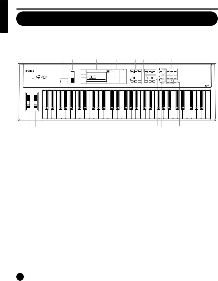
1OCTAVE [UP] and [DOWN] buttons (Page 36)
Press either of these buttons to shift the note range of the keyboard up or down in octaves. Press them together to restore the normal range (0).
2 [VOLUME] slider (Page 15)
Adjusts the master volume output from the OUTPUT L/R jacks and the PHONES jack. Move the slider upwards to raise the level.
3PITCH bend wheel (Page 44)
Controls the pitch bend effect.
4MODULATION wheel (Page 44)
Controls the modulation effect. You can also assign other parameters and functions to this controller.
5LCD (Liquid Crystal Display)
This backlit LCD displays various operation messages and information.
6Parameter Type List (Page 30)
Follow the arrow in the LCD across to the appropriate column in the list; the arrow indicates the type of the currently selected parameter.
7MODE buttons (Page 19)
Press these to buttons to select one of the modes: Multi, Voice, Utility, or another mode.
8[PART/ELEMENT/KEY] buttons
These buttons are used to select Parts/Elements/ Drum keys in the Multi Edit or Voice Edit Mode.
8-1 [+]/[–] buttons (Page 30)
In the Multi Mode, these buttons select Parts 1 to 16. In the Multi Part Edit mode, press both of these buttons simultaneously to call up the Common Edit screens. To return to the Part Edit screens, press only one of these buttons, [–] or [+].
In the Voice Edit Mode, these buttons select Elements 1 to 4 or the Drum keys. In the Voice Element Edit mode, press both of these buttons simultaneously to call up the Common Edit screens. To return to the Element Edit screens, press only one of these buttons, [–] or [+].
8-2 [MUTE] button (Page 48, 55)
In the Multi Mode, this button mutes the selected Parts. In the Voice Edit Mode, this button mutes the selected Elements or Drum keys.
8

9DATA buttons (Page 30)
These are used during editing for selecting various pages and for setting parameter values.
9-1 [DEC/NO] button (Page 31)
Use this to decrease the value of the selected parameter. To decrease the value by 10, simultaneously hold down this button and press the [INC/YES] button. The button can also be used to cancel a Job or Store operation.
9-2 [INC/YES] button (Page 31)
Use this to increase the value of the selected parameter. To increase the value by 10, simultaneously hold down this button and press the [DEC/NO] button. The button can also be used to execute a Job or Store operation.
9-3 [ ▲ ]/[ ▼ ] buttons (Page 30)
Use these to select the screen “pages” in each Mode.
9-4 [E]/[F] buttons (Page 30)
Use these to select the value to be set in the LCD, or to display continuous parts of the page (on the left and right), for pages that consist of several parts.
)[CATEGORY SEARCH/DRUM] button (Pages 34, 35)
Turns on the Category Search function (page 35). This function allows you to instantly select a desired Voice category from the numeric keypad or the Memory buttons. You can also assign the drum bank of each memory by simultaneously pressing this button and the [USER/(SE)] button or the [GM/XG /(OTHER)] button.
![PRESET/(DRUM/PERC)] button (Page 33)
In the Multi and Voice modes, this lets you select the Preset Memory programs. When the Category Search function (page 35) is active, this is used to specify the DRUM/PERC Voice category.
@[USER/(SE)] button (Page 33)
In the Multi and Voice modes, this lets you select the User Memory programs. You can also specify a User Memory Drum bank by simultaneously pressing both this button and the [CATEGORY SEARCH/DRUM] button. When the Category Search function (page 35) is active, this is used to specify the SE Voice category.
#[GM/XG/(OTHER)] button (Page 33)
In the Multi and Voice modes, this lets you select the GM/XG Memory programs. You can also specify a GM/XG Memory Drum bank by simultaneously pressing both this button and the [CATEGORY SEARCH/DRUM] button. When the Category Search function (page 35) is active, this is used to specify the OTHER: CO, ME Voice categories.
$Numeric keypad (Pages 32, 35)
This is used to select specific Multi or Program numbers. In the Edit mode, it is used to input parameter data values. The selected value is actually entered or executed only after pressing the [ENTER] button. This is also used to select the various Voice categories (page 70) when the Category Search function (page 35) is set to ON.
%[ENTER/KEYBOARD] button
This is used to enter or execute the value typed in from the numeric keypad. This can also be used to set parameters whose values are expressed as a note (from C-2 - G8); simultaneously hold this button and press the desired key on the keyboard. It is also used for executing various jobs and store operations.
&[EXIT] button (Page 31)
During editing or when in a mode other than Multi/ Voice Play, pressing this button exits from the mode and returns to the Multi/Voice Play mode.
Section Basics
9
Rear Panel
Basics Section
THRU |
MIDI |
HOST SELECT |
TO HOST |
|
OUT |
IN |
PC-2 Mac |
||
|
|
MIDI |
OFF |
|
FOOT |
FOOT |
STANDBY |
DC IN |
R |
OUTPUT |
SWITCH |
CONTROLLER |
ON |
L MONO PHONES |
||
|
|
|
|
|
|
|
|
|
|
|
|
|
|
|
|
|
|
1 |
2 3 |
4 5 |
6 7 |
8 |
9 |
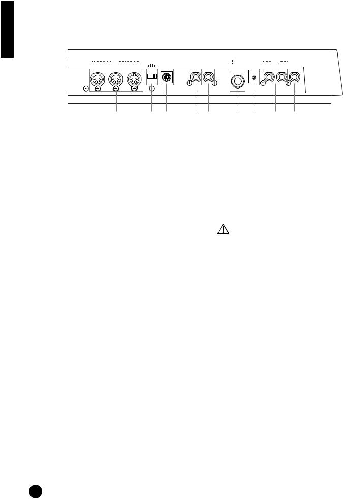
1MIDI IN/OUT/THRU terminals (Page 12)
MIDI IN receives MIDI messages from an external MIDI device. Use this connector to control the S03 from an external MIDI device. MIDI OUT sends out MIDI messages generated by the S03 (including notes played on the keyboard and panel control movements) to an external MIDI sound module or device. MIDI THRU simply relays the MIDI messages received at MIDI IN. Connect other devices here.
2HOST SELECT switch (Page 12)
For selecting the type of computer connected to the S03 via the TO HOST connector. When using the MIDI IN/OUT/THRU terminals, set this switch to MIDI.
3TO HOST terminal (Page 13)
For connection to a computer, using an optional serial computer cable.
4FOOT SWITCH jack (Pages 14, 46)
For connecting an optional footswitch (FC4 or FC5). Depending on the assigned function, you can use the footswitch to turn specific functions on and off.
5FOOT CONTROLLER jack (Pages 14, 45)
For connecting an optional foot controller (FC7, etc.). This gives you real-time control over various aspects of the sound, such as tone, pitch, and volume.
6STANDBY/ON switch (Page 15)
Use this to turn the S03 on or off.
Even when the switch is in the “STANDBY” position, electricity is still flowing to the instrument at a minimum level. When not using the S03 for an extended period of time, be sure to unplug the AC power adaptor from the wall AC outlet.
7DC IN terminal (Page 11)
For connecting an appropriate AC power adaptor (PA-3C or an equivalent recommended by Yamaha) to supply power to the S03.
8OUTPUT L/MONO and R jack (Page 11)
Line level audio signals are output from the S03 via these phone jacks (1/4" mono phone plug). For monophonic output, use just the L/MONO jack.
9PHONES jack (Page 11)
For connection to a pair of stereo headphones.
10
Before Use
This section explains how to connect to an AC power source, audio and MIDI devices, and a computer system. Only switch the S03 on after you have made all the necessary connections. We strongly recommended you read this section BEFORE using the S03.
Power Supply
S03 Rear Panel
STANDBY |
DC IN |
R |
OUTPUT |
|
ON |
L MONO PHONES |
|||
|
|
|
|
|
|
|
|
|
|
|
|
|
|
|
|
|
|
|
|
|
|
|
|
|
|
|
|
|
|
|
|
|
|
|
|
|
|
|
|
DC IN
To electrical outlet
1Make sure that the S03’s STANDBY/ON switch is at the STANDBY (off) position.
2Connect the PA-3C’s DC plug to the S03’s DC IN terminal on the instrument’s rear panel.
3Connect the adaptor’s AC plug to the nearest electrical outlet.
Do not attempt to use an AC adaptor other than the Yamaha PA-3C or an equivalent recommended by Yamaha. The use of an incompatible adaptor may cause irreparable damage to the S03, and may even pose a serious shock hazard! ALWAYS UNPLUG THE AC ADAPTOR FROM THE AC POWER OUTLET WHEN THE S03 IS NOT IN USE.
Even when the switch is in the “STANDBY” position, electricity is still flowing to the instrument at a minimum level. When not using the S03 for an extended period of time, be sure to unplug the AC power adaptor from the wall AC outlet.
Connections
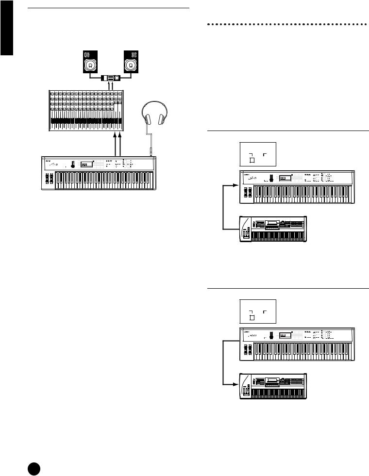
Connecting to External Audio Equipment
Since the S03 has no built-in speakers, you need to monitor its sound output via external audio equipment. Alternatively, you could use a pair of headphones.
There are several methods of connecting to external audio equipment, as described in the following illustrations.
Connecting Stereo Powered
Speakers
A pair of powered speakers can accurately produce the S03’s rich sounds with their own pan and effect settings. Connect your powered speakers to the OUTPUT L/MONO and R jacks on the rear panel.
Powered speaker |
Powered speaker |
(Left) |
(Right) |
|
Stereo headphones |
INPUT |
INPUT |
OUTPUT L / |
OUTPUT R |
MONO |
PHONES |
S03 |
nWhen using just one powered speaker, connect it to the OUTPUT L/MONO jack on the rear panel.
Section Basics
11
Basics Section
Connecting to a Mixer
If you want to integrate the S03 into a larger system with other instruments and additional audio processing capabilities, connect it to a mixer, amplifier and stereo monitor system as shown below.
|
|
|
|
|
|
|
Speaker |
|
|
|
|
|
|
|
|
|
|
Amplifier |
|
||
|
|
|
|
|
L |
|
|
|
|
R |
Mixer |
|
|
|
|
|
|
OUTPUT L |
R |
|
|
|
|
|
|
|
|
|
|
|
||
|
|
|
|
|
|
|
|
|
|
Stereo headphones |
1 2 3 |
4 |
5 |
6 |
7 |
8 |
9 |
10 11 12 13 14 15 16 |
L |
R |
|
|
|
|
|
|
|
|
OUTPUT |
|
OUTPUT |
|
|
|
|
|
|
|
|
L / MONO |
|
R |
PHONES |
Connecting External MIDI
Equipment
You can connect an external MIDI device using a MIDI cable (available separately) and control it from the S03. You can also use an external MIDI keyboard or sequencer to control the S03’s internal sounds. This section introduces several different MIDI applications.
nThe HOST SELECT switch on the rear panel should be set to “MIDI” Otherwise, MIDI data will not be transmitted from the S03’s MIDI OUT connector.
Controlling the S03 from an External MIDI Keyboard
HOST SELECT
PC-2 Mac
MIDI |
|
|
|
|
OFF |
|
|
|
|
|
|
|
|
|
|
|
|
MIDI IN
S03
nConnecting a pair of headphones does not affect audio output from the OUTPUT (L/MONO and R) jacks. The audio output at the PHONES jack and the OUTPUT
jacks is exactly the same.
MIDI OUT
S03 |
External MIDI keyboard or synthesizer
Controlling an External MIDI Keyboard with the S03
HOST SELECT
PC-2 Mac
MIDI |
|
|
|
|
OFF |
|
|
|
|
|
|
|
|
|
|
|
|
|
|
|
|
|
|
|
|
|
|
|
|
|
|
|
|
|
|
|
|
|
|
MIDI IN
S03 |
MIDI OUT
External MIDI keyboard or synthesizer
12
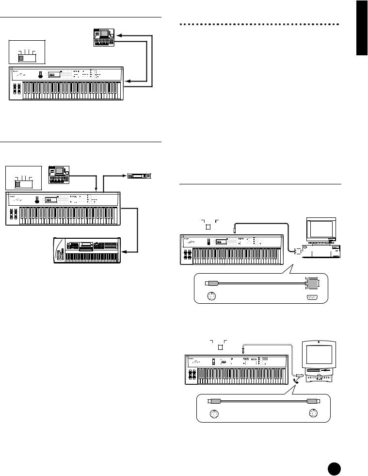
Recording and Playback using an External MIDI Sequencer
|
|
MIDI IN |
HOST SELECT |
MIDI OUT |
|
|
PC-2 Mac |
External |
MIDI |
OFF |
|
|
|
MIDI sequencer |
MIDI IN
MIDI OUT
S03
Controlling Another MIDI Device via MIDI THRU
External
|
|
MIDI sequencer |
External MIDI |
|
|
|
|
||
HOST SELECT |
|
synthesizer |
||
MIDI OUT |
MIDI IN |
|||
|
PC-2 Mac |
|||
MIDI |
OFF |
|
|
|
|
|
MIDI IN |
MIDI THRU |
|
MIDI OUT
S03 |
MIDI IN
External MIDI synthesizer
With the above MIDI connections, you can send MIDI data from the S03’s MIDI OUT terminal, while sending MIDI data from the external sequencer to an external MIDI synthesizer via the S03’s MIDI THRU terminal.
nThe MIDI cable should be no greater than 15 meters in length, and there should be no more than three devices in a MIDI chain (chained in series via each unit’s MIDI THRU). To connect more units, use a MIDI Thru Box for parallel connections. You may encounter errors if the MIDI cables are too long or if too many devices are chained together via their MIDI THRU connectors.
Connecting to a Personal Computer
You can use a connected computer to control the S03 and to transfer S03 data to/from computer via MIDI.
There are two ways to connect your S03 to a computer:
1:Serial connection (the computer’s serial port to the S03’s TO HOST terminal)
2:MIDI connection (the computer’s MIDI interface or external MIDI interface to the S03’s MIDI IN and OUT)
Depending on your particular computer, the connections may differ. (See below.)
nYou may also want to change the Local On/Off setting (page 93), depending on how you are using the S03 in your MIDI system.
1: Serial Port to TO HOST
IBM-PC/AT
HOST SELECT |
8-pin MINI DIN to |
||||
|
PC-2 Mac |
||||
|
D-SUB 9-pin Cable |
||||
MIDI |
|
|
|
OFF |
|
|
|
|
|
|
TO |
|
|
|
|
|
HOST |
|
|
|
|
|
|
|
Personal System/V |
IBM |
Personal System/V |
RS-232C |
|
(DB9) |
IBM-PC/AT |
S03 |
and compatibles |
mini DIN 8-pin |
D-SUB 9-pin |
|
|
Macintosh
HOST SELECT |
|
|
|
|
Macintosh Peripheral |
||||||||||||
|
PC-2 Mac |
|
|
|
|
||||||||||||
MIDI |
|
|
|
|
|
OFF |
|
|
|
|
|
Cable (M0197) |
|||||
|
|
|
|
|
|
|
|
|
|
|
|
TO |
|||||
|
|
|
|
|
|
|
|
|
|
|
|
HOST |
|||||
|
|
|
|
|
|
|
|
|
|||||||||
|
|
|
|
|
|
|
|
|
|||||||||
|
|
|
|
|
|
|
|
|
|
|
|
|
|
|
|
|
|
|
|
|
|
|
|
|
|
|
|
|
|
|
|
|
|
|
|
|
|
|
|
|
|
|
|
|
|
|
|
|
|
|
|
|
|
|
|
|
|
|
|
|
|
|
|
|
|
|
|
|
|
|
|
|
Macintosh |
|
S03 |
mini DIN 8-pin |
mini DIN 8-pin |
Section Basics
13
Basics Section
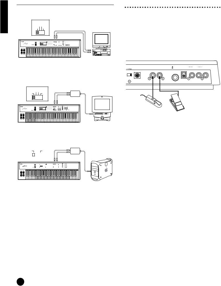
2: MIDI Interface to MIDI IN and OUT
Using the computer’s MIDI interface
HOST SELECT |
|
|
|
PC-2 PC-1 |
|
|
|
MIDI |
Mac |
|
|
|
MIDI IN |
MIDI OUT |
|
|
|
MIDI |
NEC MultiSync |
|
|
|
|
|
|
OUT |
A |
|
|
MIDI |
|
|
S03 |
IN |
Computer with |
|
|
MIDI interface |
|
Connecting Controllers
The S03 has controller jacks on the rear panel, including FOOT SWITCH and FOOT CONTROLLER. You can connect optional controllers such as a footswitch (the FC4 or FC5) and foot controller (the FC7) to control tone, volume, pitch and other parameters.
nDetails about how to use these controllers are given on page 45.
S03
|
|
|
OST SELECT |
FOOT FOOT |
STANDBY |
OUTPUT |
|
Using an external MIDI interface |
PC-2 Mac |
TO HOST |
SWITCH CONTROLLER |
ON |
DC IN R L MONO PHONES |
||
DI |
OFF |
|
|
|
|||
|
|
|
|
|
|||
■ Connection to serial port |
|
|
|
|
|
||
HOST SELECT |
MIDI Interface |
|
|
|
|
|
|
MIDI OUT |
|
|
|
|
|
||
|
PC-2 Mac |
|
|
|
|
|
|
MIDI |
OFF |
|
|
|
|
|
FOOT CONTROLLER |
|
|
MIDI IN |
|
|
|
|
|
|
|
|
|
|
|
FC7 |
|
|
|
|
|
|
|
|
|
|
MIDI IN |
MIDI OUT |
|
|
|
|
|
FOOT SWITCH
FC4 or FC5
Computer
S03
■ Connection to USB terminal
|
|
|
|
|
|
|
|
|
|
|
|
|
|
USB-MIDI interface |
||
HOST SELECT |
|
|
|
|
|
|
|
(UX256, etc.) |
||||||||
|
PC-2 Mac |
|
|
|
|
MIDI OUT |
||||||||||
MIDI |
|
|
|
|
OFF |
|
|
|
|
|
|
|
|
|
|
|
|
|
|
|
|
|
|
||||||||||
|
|
|
|
|
|
|
|
|
|
|
MIDI IN |
|||||
|
|
|
|
|
|
|
|
|
|
|
|
|
|
|
||
|
|
|
|
|
|
|
|
|
|
|
|
|
|
|
||
|
|
|
|
|
|
MIDI IN |
|
MIDI OUT |
||||||||
|
|
|
|
|
|
|
|
|
|
|
|
|
|
|
|
|
|
|
|
|
|
|
|
|
|
|
|
|
|
|
|
|
|
|
|
|
|
|
|
|
|
|
|
|
|
|
|
|
|
|
S03 |
Computer |
|
nYou will also need the appropriate MIDI application (sequencer, editor, etc.), compatible with your computer platform.
14

Powering Up
Power-on Procedure
When you have made all the necessary connections between your S03 and any other devices, make sure that all volume settings are turned down all the way to zero. Then turn on every device in your setup in the order of MIDI masters (senders), MIDI slaves (receivers), then the audio equipment (mixers, amplifiers, speakers, etc.). This ensures smooth MIDI operation and prevents speaker damage.
When powering down the setup, first turn down the volume for each audio device, then switch off each device in the reverse order (first audio devices, then MIDI).
When using the S03 as MIDI slave:
MIDI master (transmitting device)
POWER
ON!!
Turning on the S03
In order to avoid possible damage to the speakers or other connected electronic equipment, always switch on the power of the S03 before switching on the power of the amplified speakers or mixer and amplifier. Likewise, always switch off the power of the S03 after switching off the power of the amplified speakers or mixer and amplifier.
Even when the switch is in the “STANDBY” position, electricity is still flowing to the instrument at a minimum level. When not using the S03 for an extended period of time, be sure to unplug the AC power adaptor from the wall AC outlet.
nBefore you switch your S03 on or off, first turn down the volume of any connected audio equipment.
1 Press the STANDBY/ON switch
FOOT |
STANDBY |
|
DC IN |
R |
OUTPUT |
|
H CONTROLLER |
ON |
|
L MONO PHONES |
|||
|
|
|
|
|
|
|
|
|
|
|
|
|
|
|
|
|
|
|
|
|
|
|
|
|
|
|
|
Section Basics
S03 as MIDI slave (MIDI receiving device)
Audio equipment (first mixer, then amplifier)
2A splash screen (“Welcome to S03”) is displayed briefly.
3 The Multi or Voice Play Mode screen appears next.


 GrandPno
PAGE PART ELEM KEY XG001
OCTAVE
4 Turn up the amplifier’s volume as necessary.
5Adjust the S03’s [VOLUME] slider to set an appropriate volume level.
VOLUME
15
Basics Section
Demo Playback
The S03 features a variety of demo songs, showcasing its dynamic sound and sophisticated functions.
nMake sure synthesizer is ready for playback. Details are given in the section “Before Use” on page 11.
At the “Demo” screen, any data in the instrument’s User Voice memory will be overwritten by the data for the demo song. Important data should be saved to the external MIDI device or computer beforehand.
At the “DEMO” screen, the Master Tune parameter (in Utility) will be overwritten and set to “0.”
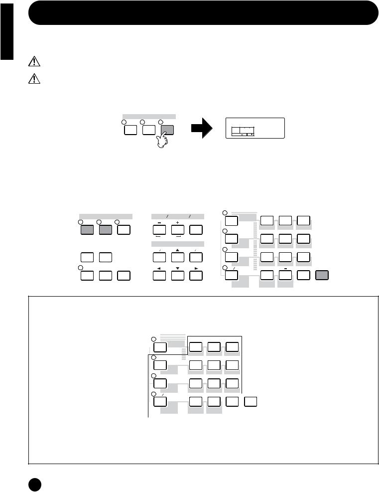
1Press the [DEMO] button. The following screen appears.
MODE
MULTI VOICE DEMO |
EraseUserV |
|
PAGE PART ELEM KEY OK? |
|
OCTAVE |
2 Press the [INC/YES] button to call up the Demo screen and automatically start playback of the Demo song.
3To stop Demo playback, press one of the following buttons: [MULTI], [VOICE], or [EXIT].
This exits from the Demo mode and automatically returns to the Multi mode, Voice mode, or the mode previously selected.
nDemo song playback continues indefinitely until stopped.
|
MODE |
PART ELEMENT KEY |
|
MULTI |
VOICE |
DEMO |
MUTE |
|
|
COMMON |
|
|
|
DATA |
|
UTILITY |
MIDI |
DEC NO |
INC YES |
EDIT |
JOB |
STORE |
|
|
CATEGORY |
7 |
8 |
9 |
|
DRUM |
|
|
|
|
|
SEARCH |
|
|
|
|
|
|
|
PIANO |
ORGAN |
GUITAR |
|
|
PRESET |
4 |
5 |
6 |
|
|
DRUM/PERC |
BASS |
STRINGS |
BRASS |
|
|
USER |
1 |
2 |
3 |
|
|
SE |
REED/PIPE |
SYN LEAD |
SYN PAD |
|
|
GM XG |
0 |
|
ENTER |
EXIT |
COMPARE |
OTHER |
|
SYN COMP CHROMATIC |
KEYBOARD |
|
||||
|
|
|
PERCUSSION |
|
Demo Song Selection
While the Demo song is playing back, you can select the particular Demo song that you wish to hear. Enter the desired Demo song category from the numeric keypad to call up the song.
|
CATEGORY |
7 |
8 |
9 |
DRUM |
|
|
|
|
SEARCH |
|
|
|
|
|
|
PIANO |
ORGAN |
GUITAR |
|
PRESET |
4 |
5 |
6 |
|
|
|
|
|
|
|
|
|
Select the |
|
|
|
|
|
|
|
|
|
|
|
|
|
|
|
|
|
|||
DRUM/PERC |
|
BASS |
STRINGS |
BRASS |
|
|
category |
||
|
|||||||||
|
|||||||||
USER |
|
1 |
2 |
|
3 |
|
|
|
|
SE |
|
REED/PIPE |
SYN LEAD |
SYN PAD |
|
|
|
||
|
|
|
|
||||||
|
|
|
|
||||||
|
|
|
|
||||||
|
|
|
|
||||||
|
|
|
|
||||||
GM XG |
|
0 |
|
|
|
|
|
|
EXIT |
|
|
|
|
ENTER |
|
|
|||
OTHER |
|
SYN COMP |
CHROMATIC |
KEYBOARD |
|
|
|
||
|
|
|
|
||||||
|
|
|
|
||||||
|
|
|
PERCUSSION |
|
|
|
|
||
|
|
|
|
|
|
|
|
|
|
For example, you can play the piano song by pressing button 7 (PIANO) in the numeric keypad. If you don’t select a particular song, an ensemble (OTHER) song will play back automatically.
nWhen there are several Demo songs contained in one category, you can select from among the available songs by using the [DEC/NO] and [INC/YES] buttons.
16
Overview of the S03
The S03 has a wide variety of advanced and convenient features. This section gives you an overview of these features.
The following diagram shows the various component sections or “blocks” of the S03.
Controller
keyboard |
controllers |
Tone Generator |
Effect |
Controller
This block consists of the keyboard, Pitch Bend and Modulation wheels and so on. The keyboard itself doesn’t generate sounds, but instead sends note, velocity and other information to the S03’s tone generator section for the notes you play. The controllers also send non-note performance data. Information from the keyboard and controllers can be transmitted to other external MIDI devices through the MIDI OUT connector.
Tone Generator
This block plays back sounds according to information received from the keyboard and controllers. The following example illustrates the path taken by the signal from an Element in the Voice Mode.
Tone Generator
OSC (Oscillator)
|
|
|
|
|
|
Controls the output level (amplitude) of each |
||||
|
|
|
|
|
|
Element output from the FILTER section. The |
||||
|
|
Controls the pitch of each Element output |
|
signals are then sent at this level to the |
||||||
|
|
from the OSC section. |
|
|
Effects Units. |
|
|
|||
|
|
|
|
|
|
|
|
|
|
|
|
|
PITCH |
|
FILTER |
|
AMP |
|
|
|
To Effects Units |
|
|
|
|
(Amplitude) |
|
|||||
|
|
|
|
|
|
|
|
|||
|
|
|
|
|
|
|
|
|
|
|
Outputs the waveform of each Element. |
Changes the tonal quality of each Element |
Each Voice consists of up to four Elements. |
output from the PITCH section. |
Section Basics
17

Basics Section
About the Tone Generator
The tone generator of the S03 utilizes the sophisticated AWM2 system.
AWM2 (Advanced Wave Memory 2) is a synthesis system based on the use of sampled waveforms, and is used in many Yamaha synthesizers. For extra realism, each AWM2 Voice uses multiple samples of a real instrument’s waveform. Furthermore, a wide variety of envelope generator, filter, modulation, and other parameters can be applied to the basic waveform.
nAWM2 is not just limited to conventional pitched instruments (Normal Voices), but also produces various drum and percussion instruments (Drum Voices). For details about Normal and Drum Voices, see page 26.
Maximum Polyphony
The maximum polyphony of the S03 is 64 notes. However, the actual note polyphony will vary depending on the number of Elements in the Voice. To calculate the actual polyphony, divide the total polyphony of 64 by the number of Elements in the Voice. For instance, if a Voice consists of two Elements, the maximum note polyphony for the Voice is 32.
Effects
The effects can be used to change or enhance the sound of a Multi or Voice.
These include the effects of the Reverb section (11 types) for adding ambient after-tones to the sound, the Chorus section (11 types) that add animation and depth, and the Variation section (42 types) which features a wealth of additional effects.
nFor more details about the effects, see page 53.
18
About the Modes
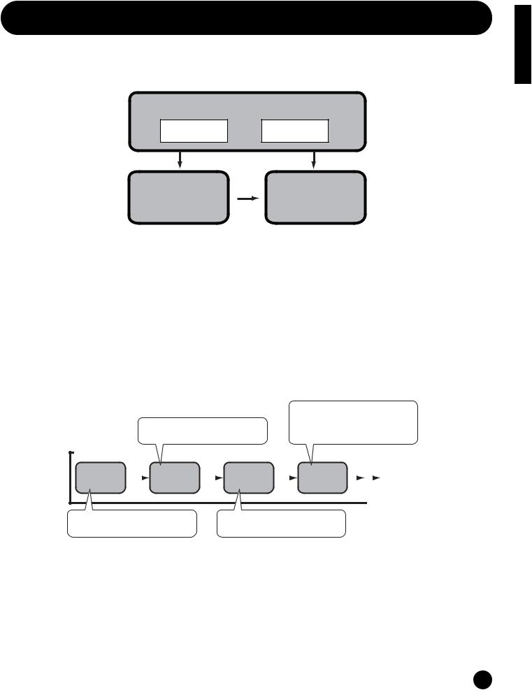
The S03 has various modes, each covering a different set of operations and functions.
Multi Mode |
Voice Mode |
|
Multi Play Mode |
Voice Play Mode |
|
Multi Edit Mode |
Voice Edit Mode |
|
Multi Job Mode |
Voice Job Mode |
|
|
MODE |
|
MULTI |
VOICE |
DEMO |
|
|
DEMO Mode |
UTILITY |
MIDI |
|
Utility Mode |
|
MIDI Mode |
EDIT |
JOB |
STORE |
|
|
Store Mode |
COMPARE |
|
|
Multi Mode |
Voice Mode |
(Page 55) |
(Page 70) |
Multi Play Mode
Select this mode when you want to use the S03 as a multi-timbral tone generator. In this mode, you can use an external MIDI sequencer to play several different instrument parts simultaneously. This mode can also be used to combine several different Voices together in a layer.
Multi Edit Mode
In this mode, you can edit and create Multis. You can save up to 32 Multis to internal memory.
Multi Job Mode
In this mode, you can copy and initialize Multis, and perform other similar operations (Jobs).
Voice Play Mode
Normal Voices and Drum Voices can be played in this mode. You can select from the Preset Voices (128 Normal Voices), User Voices (128 Normal Voices plus two Drum Kits) and XG Voices (480 Normal Voices plus 20 Drum Kits). The S03 also features a convenient Category Search function that lets quickly select a Voice according to its instrument type.
Voice Edit Mode
Normal Voices and Drum Voices can be created and edited in this mode. You can save up to 128 edited Normal Voices and two edited Drum Kits as User Voices in internal memory.
DEMO Mode (Page 16)
In this mode, you can play the Demo songs contained in internal memory. The various Demo songs play back continuously.
Utility Mode (Page 90)
This mode contains global settings related to the entire system of the S03, such as master tuning and controller-related settings.
MIDI Mode (Page 93)
In this mode, you can make MIDIrelated settings, such as the MIDI transmit/receive channels and device number.
Voice Job Mode
In this mode, you can copy Elements and initialize Voices, and perform other similar operations (Jobs).
Store Mode (Pages 69, 89)
In this mode, you can store your original Voices and Multis to internal memory.
Section Basics
19

Basics Section
Function Tree chart
LCD Display (parameter name) |
LCD |
Owner's Manual |
|
PAGE |
Page |
Multi Edit |
|
56 |
Common |
|
|
GENERAL |
|
|
Name |
1 |
56 |
Total Vol (Total Volume) |
2 |
56 |
Transpose |
3 |
56 |
EFFECT |
|
|
RevEF (Reverb Effect Type) |
4 |
56 |
Reverb Parameters |
5 |
56 |
Rev Return (Reverb Return) |
6 |
56 |
Reverb Pan |
7 |
57 |
ChoEF (Chorus Effect Type) |
8 |
57 |
Chorus Parameters |
9 |
57 |
Cho Return (Chorus Return) |
10 |
57 |
Chorus Pan |
11 |
57 |
SndCho Rev (Send Chorus to Reverb) |
12 |
57 |
VarEF (Variation Effect Type) |
13 |
57 |
Variation Parameters |
14 |
57 |
VarConnect (Variation Connection) |
15 |
58 |
Var Return (Variation Return) |
16 |
58 |
Var Pan |
17 |
58 |
SndVar Rev (Send Variation to Reverb) |
18 |
58 |
SndVar Rev (Send Variation to Chorus) |
19 |
58 |
MW VarCtl (MW Variation Effect Control Depth) |
20 |
58 |
AC1VarCtl (AC1 Variation Effect Control Depth) |
21 |
59 |
Part |
|
|
VOICE |
|
|
Voice Selection |
1 |
59 |
MIX |
|
|
Volume |
2 |
60 |
Pan |
3 |
60 |
NtLmt-H (Note Limit Low/High) |
4 |
60 |
VelLmt-L (Velocity Limit Low/High) |
5 |
60 |
GENERAL |
|
|
Rcv Ch (MIDI Receive Channel) |
6 |
61 |
NoteShift/Detune |
7 |
61 |
Mono/Poly |
8 |
61 |
Part Mode |
9 |
61 |
TONE |
|
|
VelSnsDpt/Ofs (Velocity Sensitivity Depth/Offset) |
10 |
62 |
Cutoff/Resonance |
11 |
63 |
Attack/Decay/Releas Tm (Attack/Decay/Release Time) |
12 |
63 |
PEG L/Tm (PEG Level/Time) |
13 |
64 |
Vib Rate/Depth/Delay (Vibrato Rate/Depth/Delay) |
14 |
64 |
CONTROLLER |
|
|
Porta Sw/Time (Portamento Switch/Time) |
15 |
65 |
PB Range (Pitch Bend Range) |
16 |
65 |
MW FltCtl (MW Filter Control) |
17 |
65 |
MW PMod (MW Pitch Modulation Depth) |
18 |
65 |
MW FMod (MW Filter Modulation Depth) |
18 |
65 |
MW AMod (MW Amplitude Modulation Depth) |
18 |
65 |
AC1 CC No (AC1 Control Change Number) |
19 |
66 |
AC1FltCtl (AC1 Filter Control) |
20 |
66 |
AC1 FMod (AC1 Filter Modulation Depth) |
21 |
66 |
AC1 AMod (AC1 Amplitude Modulation Depth) |
21 |
66 |
EFFECT |
|
|
ReverbSend |
22 |
66 |
ChorusSend |
23 |
66 |
Var Send (Variation Send) |
24 |
67 |
Multi Job |
|
67 |
Init (Initialize) |
1 |
68 |
CpyVar (Copy Variation Effect) |
2 |
68 |
CpyCtl (Copy Controller) |
3 |
68 |
CpyPart (Copy Part) |
4 |
68 |
BlkDmp (Bulk Dump) |
5 |
68 |
|
LCD Display (parameter name) |
LCD |
Owner's Manual |
|
|
PAGE |
Page |
Voice Edit |
|
71 |
|
Common |
|
|
|
GENERAL |
|
|
|
|
Name |
1 |
71 |
|
Total Vol/Lvl (Total Volume/Level) |
2 |
71 |
|
Mono/Poly |
3 |
71 |
|
VelSnsDpt/Ofs (Velocity Sensitivity Depth/Offset) |
4 |
72 |
|
|||
CONTROLLER |
|
|
|
|
Porta Sw/Time (Portamento Switch/Time) |
5 |
72 |
|
PB Range (Pitch Bend Range) |
6 |
72 |
|
MW FltCtl (MW Filter Control) |
7 |
72 |
|
MW PMod (MW Pitch Modulation Depth) |
8 |
72 |
|
MW FMod (MW Filter Modulation Depth) |
8 |
72 |
|
MW AMod (MW Amplitude Modulation Depth) |
8 |
72 |
|
AC1FltCtl (AC1 Filter Control) |
9 |
72 |
|
AC1 FMod (AC1 Filter Modulation Depth) |
10 |
72 |
|
AC1 AMod (AC1 Amplitude Modulation Depth) |
10 |
72 |
|
|||
EFFECT |
|
|
|
|
ReverbSend |
11 |
72 |
|
ChorusSend |
12 |
72 |
|
SndCho Rev (Send Chorus to Reverb) |
13 |
72 |
|
VarEF (Variation Effect Type) |
14 |
72 |
|
Variation Parameters |
15 |
72 |
|
MW VarCtl (MW Variation Effect Control Depth) |
16 |
72 |
|
AC1 VarCtl (AC1 Variation Effect Control Depth) |
17 |
72 |
|
|||
Element |
|
|
|
OSC/MIX (Oscillator/Mixer) |
|
|
|
|
Element Sw (Element Switch) |
1 |
73 |
|
Wave Selection |
2 |
73 |
|
Level |
3 |
73 |
|
Pan |
4 |
73 |
|
NtLmt-L/H (Note Limit Low/High) |
5 |
73 |
|
VelLmt-L/H (Velocity Limit Low/High) |
6 |
74 |
|
|||
PITCH |
|
|
|
|
NoteShift/Detune |
7 |
74 |
|
PchSclSns (Pitch Scale Sensitivity) |
8 |
74 |
|
PchSclCN (Pitch Scale Center Note) |
8 |
74 |
|
PEG R (PEG Rate) |
9 |
75 |
|
PEG L (PEG Level) |
10 |
75 |
|
PEGSclSns (PEG Scale Sensitivity) |
11 |
76 |
|
PEGSclCN (PEG Scale Center Note) |
11 |
76 |
|
PEGRtVel (PEG Rate Velocity) |
12 |
76 |
|
PEGLvlVel (PEG Level Velocity) |
12 |
76 |
|
|||
FILTER |
|
|
|
|
Cutoff/Resonance |
13 |
77 |
|
CutoffVel (Cutoff Velocity Sensitivity) |
14 |
77 |
|
ResoVel (Resonance Velocity Sensitivity) |
14 |
77 |
|
FltSclFlag (Filter Scale Flag) |
15 |
77 |
|
Flt BP1~4 (Filter Scale Break Point 1~4) |
16 |
78 |
|
Flt Ofs1~4 (Filter Scale Offset 1~4) |
17 |
78 |
|
FltSclSns (Filter Scale Sensitivity) |
18 |
78 |
|
FltSclVel (Filter Scale Velocity Sensitivity) |
18 |
78 |
|
FEG R (FEG Rate) |
19 |
79 |
|
FEG L (FEG Level) |
20 |
79 |
|
FEGSclSens (FEG Scale Sensitivity) |
21 |
79 |
|
FEGAtkVel (FEG Attack Velocity) |
22 |
80 |
|
FEGOthVel (FEG Other Velocity) |
22 |
80 |
|
|||
AMP (Amplitude) |
|
|
|
|
AEG R (AEG Rate) |
23 |
80 |
|
AEG L (AEG Level) |
24 |
80 |
|
AEGSclSens (AEG Scale Sensitivity) |
25 |
81 |
|
AEGLvlVel (AEG Level Velocity Sensitivity) |
26 |
81 |
|
AEGAtkVel (AEG Attack Velocity Sensitivity) |
26 |
81 |
|
LvlSclFlag (AEG Level Scale Flag) |
27 |
81 |
|
Lvl BP1~4 (Level Break Point 1~4) |
28 |
81 |
|
Lvl Ofs1~4 (Level Offset 1~4) |
29 |
82 |
|
LvlSclSens (Level Scale Sensitivity) |
30 |
82 |
|
KeyonDelay |
31 |
82 |
|
|||
LFO (Low Frequency Oscillator) |
|
|
|
|
LFO Wave |
32 |
82 |
|
LFO Phase (LFO Phase Initialize) |
32 |
82 |
|
LFO Speed |
33 |
83 |
|
LFO PMod (LFO Pitch Modulation) |
34 |
83 |
|
LFO FMod (LFO Filter Modulation) |
34 |
83 |
|
LFO AMod (LFO Amplitude Modulation) |
34 |
83 |
|
PLFODelay (Pitch LFO Delay) |
35 |
83 |
|
PLFO Fade (Pitch LFO Fade Time) |
35 |
83 |
|
|||
20
LCD Display (parameter name) |
LCD |
Owner's Manual |
|
PAGE |
Page |
Voice Edit (Drum) |
|
84 |
Common |
|
|
GENERAL |
|
|
Name |
1 |
85 |
OrgKt (Original Kit) |
2 |
85 |
Key |
|
|
OSC/MIX (Oscillator/Mixer) |
|
|
Level |
1 |
85 |
Pan |
2 |
85 |
Alt.Group (Alternate Group) |
3 |
85 |
Key Assign |
4 |
85 |
RxNoteOff/On (Receive Note On/Off) |
5 |
86 |
PITCH |
|
|
PitchCors/Fine (Pitch Coarse/Fine) |
6 |
86 |
FILTER |
|
|
Cutoff/Resonance |
7 |
86 |
AMP (Amplitude) |
|
|
EG Attack/Decay1/Decay2(EG Attack/Decay1/Decay2 Rate) |
8 |
86 |
EFFECT |
|
|
ReverbSend |
9 |
87 |
ChorusSend |
10 |
87 |
Voice Job |
|
87 |
Init (Initialize) |
1 |
88 |
CpyElm (Copy Element)/CpyKey (Copy Drum Key) |
2 |
88 |
BlkDmp (Bulk Dump) |
3 |
88 |
DEMO Mode |
|
16 |
|
|
Demo Song Play |
|
16 |
Utility Mode |
|
90 |
|
TG (Tone Generator) |
|
|
|
|
MasterTune |
1 |
90 |
KEYBOARD |
|
|
|
|
Kbd Trans (Keyboard Transpose) |
2 |
90 |
|
Vel Curve (Velocity Curve) |
3 |
90 |
|
Fixed Vel (Fixed Velocity) |
3 |
90 |
CONTROLLER |
|
|
|
|
MWTxCtlNo (MW Transmit Control Number) |
4 |
91 |
|
FCTxCtlNo (Foot Controller Transmit Control Number) |
4 |
91 |
|
FSTxCtlNo (Footswitch Transmit Control Number) |
5 |
91 |
|
Ctl Reset (Controller Reset) |
6 |
91 |
|
AC1 CC No (AC1 Control Change Number) |
7 |
92 |
EFFECT |
|
|
|
|
V EfBypass (Voice Effect Bypass) |
8 |
92 |
|
|||
MIDI Mode |
|
93 |
|
MIDI CHANNEL |
|
|
|
|
Device No (Device Number) |
1 |
93 |
|
Local Sw (Local On/Off Switch) |
2 |
93 |
|
Rcv Ch (Voice Mode MIDI Receive Channel) |
3 |
94 |
|
Trans Ch (MIDI Transmit Channel) |
4 |
94 |
|
|||
MIDI FILTER |
|
|
|
|
RxPgmChng (Receive Program Change On/Off) |
5 |
94 |
|
RxBankSel (Receive Bank Select On/Off) |
5 |
94 |
|
TxPgmChng (Transmit Program Change On/Off) |
6 |
94 |
|
TxBankSel (Transmit Bank Select On/Off) |
6 |
94 |
|
Thru Port |
7 |
94 |
|
|||
nFor details about the Multi Store procedure, see page 69; for details about the Voice Store procedure, see page 89.
Section Basics
21

Basics Section
Parameter Table
The numbers in each column indicate the display PAGE corresponding to the parameter at left (with the exception of the column on the far right, which indicates the corresponding manual page). For example, you can see that the Reverb Send parameter is found on three separate display pages: PAGE 22 of Multi Part Edit, PAGE 11 of Normal Voice Common Edit, and PAGE 9 of Drum Voice Key Edit.
This table is helpful in locating the corresponding display pages in different modes. This is handy when you want to make the same or similar settings to the same parameter in a different mode — for example, setting the Reverb Send in the Multi mode to the same value as Reverb Send in the Voice mode. It’s also handy for cross-checking same parameters for programming complex sound changes — such as setting the Voice’s Filter Cutoff to a certain value, then going to Cutoff in the Multi mode and tweaking it further.
Since the owner’s manual page reference is also provided, you can quickly find the corresponding explanation by checking the currently selected mode and PAGE number on the S03, and referring to this table.
nWhen the parameter is the same for both the Voice mode and Multi mode, the manual page reference is generally for the explanation in the Multi mode.
|
|
Multi Edit |
|
Voice Edit |
|
|
|
Owner's |
||
Parameter Type |
LCD Display (parameter name) |
Common |
Part |
Common |
Element/Key |
UTILITY |
MIDI |
Manual |
||
|
|
Normal |
Drum |
Normal |
Drum |
|
|
Page |
||
|
|
|
|
|
|
|||||
|
|
|
|
|
|
|
||||
GENERAL |
Name |
1 |
|
1 |
1 |
|
|
|
|
56, 71 |
|
Total Vol (Total Volume) |
2 |
|
2 |
|
|
|
|
|
56, 71 |
|
Total Lvl (Level) |
|
|
2 |
|
3 |
1 |
|
|
71, 73, 85 |
|
Transpose |
3 |
|
|
|
|
|
|
|
56 |
|
Rcv Ch (MIDI Receive Channel) |
|
6 |
|
|
|
|
|
3 |
61, 94 |
|
NoteShift/Detune |
|
7 |
|
|
7 |
|
|
|
61, 74 |
|
Mono/Poly |
|
8 |
3 |
|
|
|
|
|
61, 71 |
|
Part Mode |
|
9 |
|
|
|
|
|
|
61 |
|
OrgKt (Original Kit) |
|
|
|
2 |
|
|
|
|
85 |
EFFECT* |
RevEF (Reverb Effect Type) |
4 |
|
|
|
|
|
|
|
56 |
|
Reverb Parameters |
5 |
|
|
|
|
|
|
|
56 |
|
Rev Return (Reverb Return) |
6 |
|
|
|
|
|
|
|
56 |
|
Reverb Pan |
7 |
|
|
|
|
|
|
|
57 |
|
ChoEF (Chorus Effect Type) |
8 |
|
|
|
|
|
|
|
57 |
|
Chorus Parameters |
9 |
|
|
|
|
|
|
|
57 |
|
Cho Return (Chorus Return) |
10 |
|
|
|
|
|
|
|
57 |
|
Chorus Pan |
11 |
|
|
|
|
|
|
|
57 |
|
SndCho Rev (Send Chorus to Reverb) |
12 |
|
13 |
|
|
|
|
|
57 |
|
VarEF (Variation Effect Type) |
13 |
|
14 |
|
|
|
|
|
57 |
|
Variation Parameters |
14 |
|
15 |
|
|
|
|
|
57 |
|
VarConnect (Variation Connection) |
15 |
|
|
|
|
|
|
|
58 |
|
Var Return (Variation Return) |
16 |
|
|
|
|
|
|
|
58 |
|
Var Pan |
17 |
|
|
|
|
|
|
|
58 |
|
Snd Var Rev (Send Variation to Reverb) |
18 |
|
|
|
|
|
|
|
58 |
|
Snd Var Cho (Send Variation to Chorus) |
19 |
|
|
|
|
|
|
|
58 |
|
MW VarCtl (MW Variation Effect Control Depth) |
20 |
|
16 |
|
|
|
|
|
58 |
|
AC1VarCtl (AC1 Variation Effect Control Depth) |
21 |
|
17 |
|
|
|
|
|
66 |
|
ReverbSend |
|
22 |
11 |
|
|
9 |
|
|
66 |
|
ChorusSend |
|
23 |
12 |
|
|
10 |
|
|
66 |
|
Var Send (Variation Send) |
|
24 |
|
|
|
|
|
|
67 |
|
V EfBypass (Voice Effect Bypass) |
|
|
|
|
|
|
8 |
|
92 |
VOICE |
Voice Selection |
|
1 |
|
|
|
|
|
|
59 |
MIX |
Volume |
|
2 |
|
|
|
|
|
|
60 |
|
Pan |
|
3 |
|
|
4 |
2 |
|
|
60, 73, 85 |
|
NtLmt-H (Note Limit Low/High) |
|
4 |
|
|
5 |
|
|
|
60, 73 |
|
VelLmt-L (Velocity Limit Low/High) |
|
5 |
|
|
6 |
|
|
|
60, 74 |
TONE |
VelSnsDpt/Ofs (Velocity Sensitivity Depth/Offset) |
|
10 |
4 |
|
|
|
|
|
62 |
|
Cutoff/Resonance |
|
11 |
|
|
13 |
7 |
|
|
63, 77, 86 |
|
Attack/Decay/Release Tm (Attack/Decay/Release Time) |
|
12 |
|
|
|
|
|
|
63 |
|
PEG L/Tm (PEG Level/Time) |
|
13 |
|
|
|
|
|
|
64 |
|
Vib Rate/Depth/Delay (Vibrato Rate/Depth/Delay) |
|
14 |
|
|
|
|
|
|
64 |
CONTROLLER* |
Porta Sw/Time (Portamento Switch/Time) |
|
15 |
5 |
|
|
|
|
|
65 |
|
PB Range (Pitch Bend Range) |
|
16 |
6 |
|
|
|
|
|
65 |
|
MW FltCtl (MW Filter Control) |
|
17 |
7 |
|
|
|
|
|
65 |
|
MW PMod (MW Pitch Modulation Depth) |
|
18 |
8 |
|
|
|
|
|
65 |
|
MW FMod (MW Filter Modulation Depth) |
|
18 |
8 |
|
|
|
|
|
65 |
|
MW AMod (MW Amplitude Modulation Depth) |
|
18 |
8 |
|
|
|
|
|
65 |
|
AC1 CC No (AC1 Control Change Number) |
|
19 |
|
|
|
|
7 |
|
66, 92 |
|
AC1FltCtl (AC1 Filter Control) |
|
20 |
9 |
|
|
|
|
|
66 |
|
AC1 FMod (AC1 Filter Modulation Depth) |
|
21 |
10 |
|
|
|
|
|
66 |
|
AC1 AMod (AC1 Amplitude Modulation Depth) |
|
21 |
10 |
|
|
|
|
|
66 |
|
MWTxCtlNo (MW Transmit Control Number) |
|
|
|
|
|
|
4 |
|
91 |
|
FCTxCtlNo (Foot Controller Transmit Control Number) |
|
|
|
|
|
|
4 |
|
91 |
|
FSTxCtlNo (Footswitch Transmit Control Number) |
|
|
|
|
|
|
5 |
|
91 |
|
Ctl Reset (Controller Reset) |
|
|
|
|
|
|
6 |
|
91 |
22

|
|
|
|
|
|
|
|
|
|
|
Basics |
|
|
Multi Edit |
Normal |
Drum |
Normal |
Drum |
|
|
Page |
||
|
|
|
Voice Edit |
|
|
|
Owner's |
|
|||
Parameter Type |
LCD Display (parameter name) |
Common |
Part |
Common |
Element/Key |
UTILITY |
MIDI |
Manual |
|
||
|
|
|
|
|
|
|
|
|
|
|
Section |
OSC/MIX (Oscillator/Mixer) |
Alt.Group (Alternate Group) |
|
|
|
|
1 |
3 |
|
|
85 |
|
Element Sw (Element Switch) |
|
|
|
|
|
|
|
73 |
|
||
|
Wave Selection |
|
|
|
|
2 |
|
|
|
73 |
|
|
Level |
|
|
|
|
3 |
|
|
|
85 |
|
|
|
|
|
|
|
|
|
|
|
|
|
|
Key Assign |
|
|
|
|
|
4 |
|
|
85 |
|
|
RxNoteOff/On (Receive Note On/Off) |
|
|
|
|
|
5 |
|
|
86 |
|
PITCH |
NoteShift/Detune |
|
7 |
|
|
7 |
|
|
|
61, 74 |
|
|
PchSclSns (Pitch Scale Sensitivity) |
|
|
|
|
8 |
|
|
|
74 |
|
|
PchSclCN (Pitch Scale Center Note) |
|
|
|
|
8 |
|
|
|
74 |
|
|
PEG R (PEG Rate) |
|
|
|
|
9 |
|
|
|
75 |
|
|
PEG L (PEG Level) |
|
|
|
|
10 |
|
|
|
75 |
|
|
PEGSclSns (PEG Scale Sensitivity) |
|
|
|
|
11 |
|
|
|
76 |
|
|
PEGSclCN (PEG Scale Center Note) |
|
|
|
|
11 |
|
|
|
76 |
|
|
PEGRtVel (PEG Rate Velocity) |
|
|
|
|
12 |
|
|
|
76 |
|
|
PEGLvlVel (PEG Level Velocity) |
|
|
|
|
12 |
|
|
|
76 |
|
|
PitchCors/Fine (Pitch Coarse/Fine) |
|
|
|
|
|
6 |
|
|
86 |
|
FILTER |
Cutoff/Resonance |
|
11 |
|
|
13 |
7 |
|
|
63, 77, 86 |
|
|
CutoffVel (Cutoff Velocity Sensitivity) |
|
|
|
|
14 |
|
|
|
77 |
|
|
ResoVel (Resonance Velocity Sensitivity) |
|
|
|
|
14 |
|
|
|
77 |
|
|
FltSclFlag (Filter Scale Flag) |
|
|
|
|
15 |
|
|
|
77 |
|
|
Flt BP1~4 (Filter Scale Break Point 1~4) |
|
|
|
|
16 |
|
|
|
78 |
|
|
Flt Ofs1~4 (Filter Scale Offset 1~4) |
|
|
|
|
17 |
|
|
|
78 |
|
|
FltSclSns (Filter Scale Sensitivity) |
|
|
|
|
18 |
|
|
|
78 |
|
|
FltSclVel (Filter Scale Velocity Sensitivity) |
|
|
|
|
18 |
|
|
|
78 |
|
|
FEG R (FEG Rate) |
|
|
|
|
19 |
|
|
|
79 |
|
|
FEG L (FEG Level) |
|
|
|
|
20 |
|
|
|
79 |
|
|
FEGSclSens (FEG Scale Sensitivity) |
|
|
|
|
21 |
|
|
|
79 |
|
|
FEGAtkVel (FEG Attack Velocity) |
|
|
|
|
22 |
|
|
|
80 |
|
|
FEGOthVel (FEG Other Velocity) |
|
|
|
|
22 |
|
|
|
80 |
|
AMP (Amplitude) |
AEG R (AEG Rate) |
|
|
|
|
23 |
|
|
|
80 |
|
|
AEG L (AEG Level) |
|
|
|
|
24 |
|
|
|
80 |
|
|
AEGSclSens (AEG Scale Sensitivity) |
|
|
|
|
25 |
|
|
|
81 |
|
|
AEGLvlVel (AEG Level Velocity Sensitivity) |
|
|
|
|
26 |
|
|
|
81 |
|
|
AEGAtkVel (AEG Attack Velocity Sensitivity) |
|
|
|
|
26 |
|
|
|
81 |
|
|
LvlSclFlag (AEG Level Scale Flag) |
|
|
|
|
27 |
|
|
|
81 |
|
|
Lvl BP1~4 (Level Break Point 1~4) |
|
|
|
|
28 |
|
|
|
81 |
|
|
Lvl Ofs1~4 (Level Offset 1~4) |
|
|
|
|
29 |
|
|
|
82 |
|
|
LvlSclSens (Level Scale Sensitivity) |
|
|
|
|
30 |
|
|
|
82 |
|
|
KeyonDelay |
|
|
|
|
31 |
|
|
|
82 |
|
|
EG Attack/Decay1/Decay2(EG Attack/Decay1/Decay2 Rate) |
|
|
|
|
|
8 |
|
|
86 |
|
LFO (Low Frequency Oscillator) |
LFO Wave |
|
|
|
|
32 |
|
|
|
82 |
|
|
LFO Phase (LFO Phase Initialize) |
|
|
|
|
32 |
|
|
|
82 |
|
|
LFO Speed |
|
|
|
|
33 |
|
|
|
83 |
|
|
LFO PMod (LFO Pitch Modulation) |
|
|
|
|
34 |
|
|
|
83 |
|
|
LFO FMod (LFO Filter Modulation) |
|
|
|
|
34 |
|
|
|
83 |
|
|
LFO AMod (LFO Amplitude Modulation) |
|
|
|
|
34 |
|
|
|
83 |
|
|
PLFODelay (Pitch LFO Delay) |
|
|
|
|
35 |
|
|
|
83 |
|
|
PLFO Fade (Pitch LFO Fade Time) |
|
|
|
|
35 |
|
|
|
83 |
|
TG (Tone Generator) |
MasterTune |
|
|
|
|
|
|
1 |
|
90 |
|
KEYBOARD |
Kbd Trans (Keyboard Transpose) |
|
|
|
|
|
|
2 |
|
90 |
|
|
Vel Curve (Velocity Curve) |
|
|
|
|
|
|
3 |
|
90 |
|
|
Fixed Vel (Fixed Velocity) |
|
|
|
|
|
|
3 |
|
90 |
|
MIDI CHANNEL |
Device No (Device Number) |
|
|
|
|
|
|
|
1 |
93 |
|
|
Local Sw (Local On/Off Switch) |
|
|
|
|
|
|
|
2 |
93 |
|
|
Rcv Ch (Voice Mode MIDI Receive Channel) |
|
|
|
|
|
|
|
3 |
94 |
|
|
Trans Ch (MIDI Transmit Channel) |
|
|
|
|
|
|
|
4 |
94 |
|
MIDI FILTER |
RxPgmChng (Receive Program Change On/Off) |
|
|
|
|
|
|
|
5 |
94 |
|
|
RxBankSel (Receive Bank Select On/Off) |
|
|
|
|
|
|
|
5 |
94 |
|
|
TxPgmChng (Transmit Program Change On/Off) |
|
|
|
|
|
|
|
6 |
94 |
|
|
TxBankSel (Transmit Bank Select On/Off) |
|
|
|
|
|
|
|
6 |
94 |
|
|
Thru Port |
|
|
|
|
|
|
|
7 |
94 |
|
nFor parameters in different modes having the same name, the available parameter values and settings for that parameter may differ depending on the mode. Refer to each parameter explanation for details.
nFor details on parameters for the Reverb, Chorus and Variation effects, refer to the separate Data List.
nFor information on the Job pages, refer to the Function Tree chart (page 20).
*In the Multi mode, the Voice Common Effect/Controller settings are ignored, and the Multi settings become effective. The Variation Effect/Controller settings of the Voice mode can be copied to the Multi mode by using the Multi Job function (page 68).
23
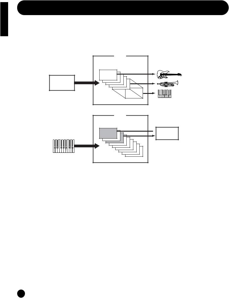
Basics Section
Multis
A Multi consists of up to 16 Parts, each of which can play a Normal Voice or Drum Voice Part.
By assigning different Voices and MIDI channels to each part, and by using a sequencer or computer for song data playback, you can have a complete ensemble of 16 independent instrument sounds.
You can also play Multis from the keyboard. This allows you to set up layers of different Voices, or special key splits in which your right and left hands can play separate Voices (page 41).
External MIDI sequencer
Song File
|
Multi |
|
Part 1~16 |
MIDI CH |
CH1 |
|
|
1~16 |
|
|
CH16 |
Multi
Part 1~16
 Two Layered
Voices
Different Voice for each part
24
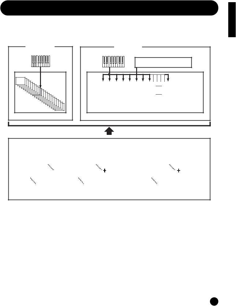
Voices
A Voice is a single instrument sound, created by using the Elements and setting various parameters. In the Voice Play mode, you can select and play any of these Voices. In the Multi Play mode, you assign a different Voice to each part and use an external sequencer to play several Voices simultaneously.
Voices are stored in the internal memory (PRESET, USER, GM/XG).
Voice Play Mode
Controllers
Tone Generator
Voice
Playing a Voice
Multi Play Mode
Controllers
External MIDI sequenser
Tone Generator
Multi
|
|
|
|
|
|
|
|
|
|
|
|
|
|
|
|
|
|
|
|
|
|
|
|
|
|
|
|
|
|
|
|
|
|
|
|
|
Part |
|
|
|
1 |
|
2 |
3 |
4 |
5 |
6 |
7 |
8 |
|
16 |
|
|
|
|
|
|
|
|||||||
|
|
|
|
|
|
|
|
|
|
|
|
|
|
|
|
|||||||||||||||||
|
|
|
|
|
|
|
|
|
|
|
|
|
|
|
|
|
|
|
|
|
|
|
|
|
|
|
|
|
|
|||
|
|
|
|
Voice |
|
|
|
|
PR |
|
|
PR |
PR |
XG |
XG |
XG |
US |
US |
|
PR |
|
|
|
|
|
|
|
|||||
|
|
|
|
|
|
|
001 |
|
|
002 |
003 |
001 |
002 |
003 |
001 |
002 |
|
016 |
|
|
|
|
|
|
|
|||||||
|
|
|
|
|
|
|
|
|
|
|
|
|
|
|
|
|
|
|
|
|||||||||||||
|
|
|
|
|
|
|
|
|
|
|
|
|
|
|
|
|
|
|
|
|
|
|
|
|
|
|
|
|
|
|
|
|
|
|
|
|
|
|
|
|
|
|
|
|
|
|
|
|
|
|
|
|
|
|
|
|
|
|
|
|
|
|
|
|
|
Playing a Multi
|
|
|
|
|
|
|
|
Preset |
|
|
|
|
|
|
|
|
|
|
|
|
GM/XG Voice |
|
|
|
|
|
|
|
|
|
|
|
|
|
|
|
|
User |
|
|
|
|
|
||||||||||
|
|
|
|
|
|
|
|
|
|
|
|
|
|
|
|
|
|
|
|
|
|
|
|
|
|
|
|
|
|
|
|
|
|||||||||||||||||||||
|
|
128 Preset Voice |
|
|
|
|
|
|
|
|
|
|
|
|
|
|
|
|
|
|
|
|
|
|
|
|
|
|
|
|
|
|
|
128 User Voice |
|||||||||||||||||||
|
|
|
|
|
|
|
|
|
|
|
|
|
|
|
|
|
|
|
|
|
|
|
|
|
|
|
|
|
|
|
|
|
|
|
|
|
|
|
|
|
|
|
|
|
|
|
|
|
|
|
|
|
|
|
|
|
|
|
|
|
|
PR001~128 |
|
|
|
|
|
|
|
|
|
|
|
|
480 |
|
|
|
|
|
|
|
|
|
|
|
|
|
|
|
|
|
|
|
US001~128 |
|
|
|
|
|
|
|
|
|
|||
|
|
|
|
|
|
|
|
|
|
|
|
|
|
|
|
|
|
|
NormalVoice |
|
|
|
|
|
|
|
|
|
|
|
|
|
|
|
|
|
|
|
|
|
|
|
|
|
|
||||||||
|
|
|
|
|
|
|
|
|
|
|
|
|
|
|
|
|
|
|
|
|
|
|
|
|
|
|
|
|
|
|
|
|
|
|
|
|
|
|
|
|
|
|
|
|
|
|
|
|
|
|
2 User |
||
|
|
|
|
|
|
|
|
|
|
|
|
|
|
|
|
|
|
|
|
|
|
|
|
|
|
|
|
|
|
|
|
|
|
|
|
|
|
|
|
|
|
|
|
|
|
|
|
|
Drum Voice |
||||
|
|
|
|
|
|
|
|
|
|
|
|
|
|
|
|
|
|
|
|
|
|
|
|
|
|
|
|
20 Drum Voice * |
|
|
|
|
|
|
|
|
|
|
|
|
|
|
|
|
|
|
|
||||||
|
|
|
|
|
|
|
|
|
|
|
|
|
|
|
|
|
|
|
|
|
|
|
|
|
|
|
|
|
|
|
|
|
|
|
|
|
|
||||||||||||||||
|
|
|
|
|
|
|
|
|
|
|
|
|
|
|
|
|
|
|
|
|
|
|
|
|
|
|
|
|
|
|
|
|
|
|
|
|
|
||||||||||||||||
|
|
|
|
|
|
|
|
|
|
|
|
|
|
|
|
|
|
|
|
|
|
|
|
|
|
|
|
|
|
|
|
|
|
|
|
|
|
|
|
|
|
|
|
|
|
|
|
|
|
|
|
|
|
* Drum Voices XG121~128 are not of the GM/XG set, but are original drum kits specifically programmed for the S03.
Section Basics
25
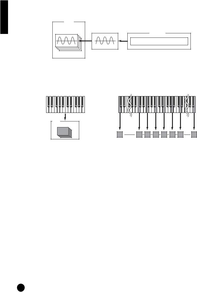
Basics Section
Overview of Voices/Waves
Each Voice can consist of up to four Elements. Each Element itself is a high-quality waveform or instrument sound.
Voice |
|
Element 1~4 |
Element |
Wave form
AWM2: 453 Prest waveforms
There are two Voice types: Normal Voices and Drum Voices. Normal Voices are mainly pitched instrument sounds that can be played over the range of the keyboard. Drum Voices are mainly percussion/drum sounds that are assigned to individual notes on the keyboard. The Drum Voices also include special sound effects.
In general, a Voice (containing up to four Elements) can be played across the entire range of the keyboard. However, this can be changed; the actual key range for the Voice is determined by the Note Limit parameters (page 73).
Nomal Voice |
Drum Voice |
Voice
Element 1~4
Individual drum sounds (different for each key)
nA total of 480 (XG) and 128 (Preset) Normal Voices plus 20 Drum Voices are available as presets. You can create and store your own original Voices; the S03 has User memory space for 128 User Normal Voices and two User Drum Voices.
26
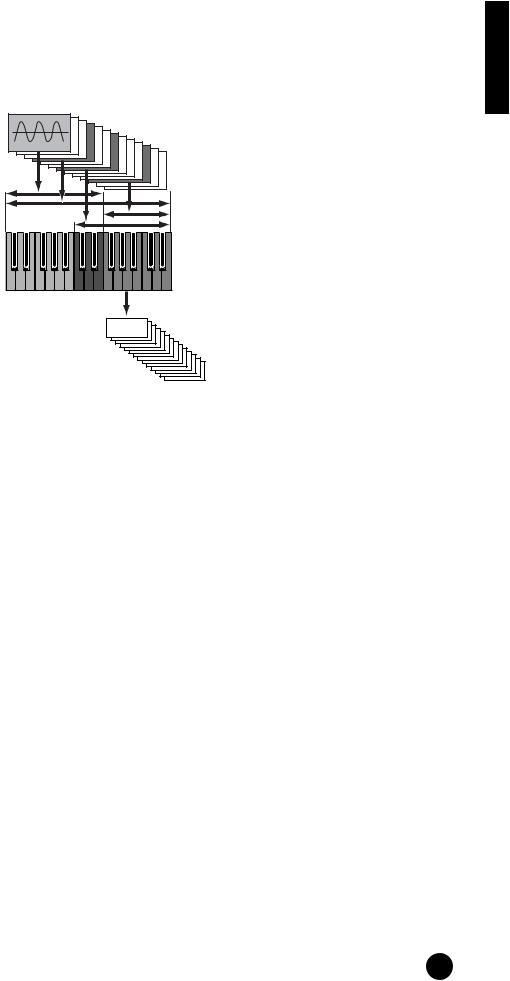
Waves
Waves (or waveforms) are the basic sonic building blocks, and are used as Elements in making up a Voice. A total of 453 high-quality preset Waves are available. As shown in the following illustration, when creating a Voice, you can select the Wave to be used as an Element and then set its level, pitch, tone and other parameters.
Wave 1~453
Element 1
Element 2
Element 3
Element 4
C-2 |
G8 |
Voice
Section Basics
27
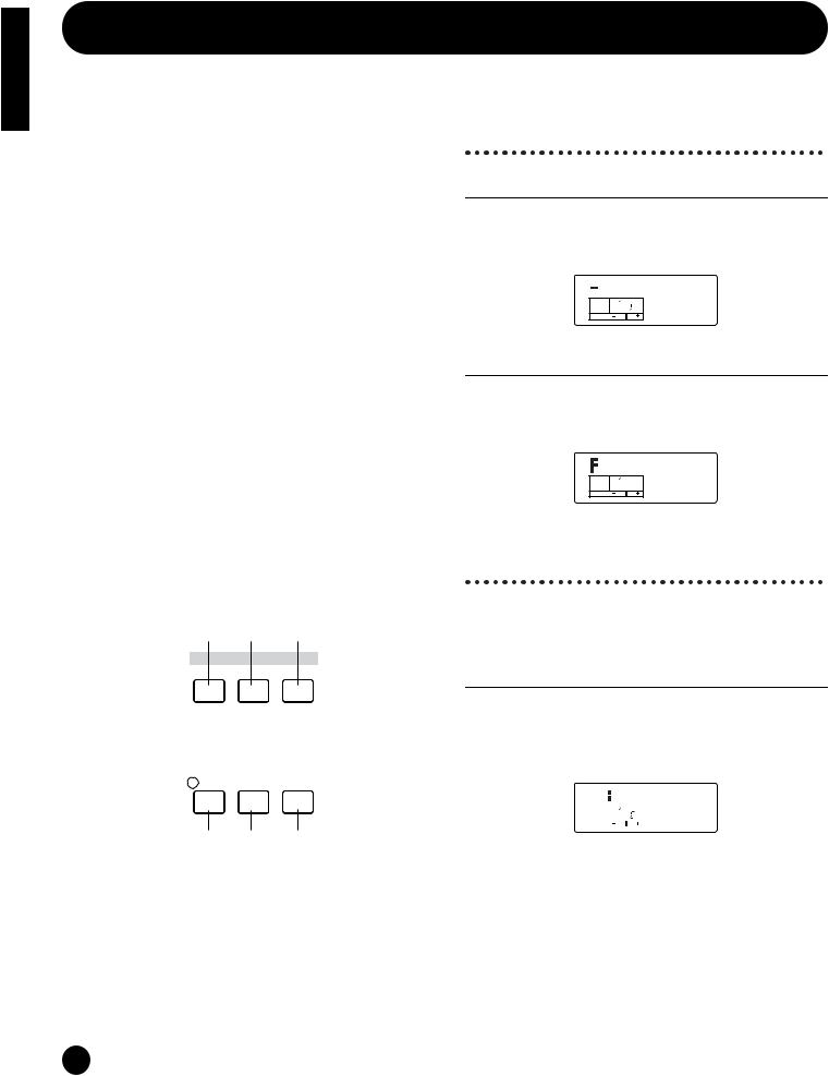
Basics Section
Basic Operations
In this section, you’ll learn the fundamental operations of the S03.
Selecting a Mode
There are several operation modes — the Multi Play mode, Voice Play mode, etc. — each of which enables you to work efficiently with the S03’s various functions.
nFor an overview of the various modes, see page 19.
There are separate Play modes for Multis and Voices. To enter each of these modes, use the appropriate MODE button ([Multi] for Multi Play mode, [VOICE] for Voice Play mode).
There are also separate Edit and Job modes for Multis and Voices. To enter the Edit or Job mode, simply press the [EDIT] or [JOB] button while in each respective Play mode.
Similarly, pressing the [STORE] button in the Multi or Voice mode takes you into the Store mode where you can store Multis or Voices.
In addition the modes mentioned above, there is also a Utility mode, which is for making global settings to the instrument, and the MIDI mode, which contains MIDIrelated settings. Finally, there is the Demo mode, which allows you to play back the Demo songs.
To select these, press the [UTILITY] button for the Utility mode, the [MIDI] button for the MIDI mode and the [DEMO] button for the Demo mode.
1 2 7
MODE
 MULTI
MULTI  VOICE
VOICE  DEMO
DEMO
UTILITY MIDI
5
 6
6
EDIT |
JOB |
STORE |
COMPARE
3 4 8
Play Modes
1 Multi Play Mode (Page 37)
Press the [MULTI] button (the LED lights) to enter the Multi Play mode. To exit to another mode, simply press the respective button for that mode.

 Init Mlt
PAGE PARTPELEM KEY MLT01
OCTAVE
2 Voice Play Mode (Page 33)
Press the [VOICE] button (the LED lights) to enter the Voice Play mode. To exit to another mode, simply press the respective button for that mode.


 GrandPno
PAGE PART ELEM KEY XG001
OCTAVE
Edit Modes
There are also separate Edit and Job modes for each Play mode. The [EDIT] lamp lights along with the appropriate Play mode lamp, [MULTI] or [VOICE].
3 Multi Edit Mode (Page 55)
Press the [EDIT] button in the Multi Play mode. To exit to another mode, simply press the respective button for that mode. Press the [EXIT] button to return to the Multi Play mode.
|
|
|
|
Init Mlt |
|
|
|
|
|
||
PAGE |
PART ELEM KEY |
|
|||
1 |
|
P |
Name |
||
OCTAVE |
|
|
|||
28
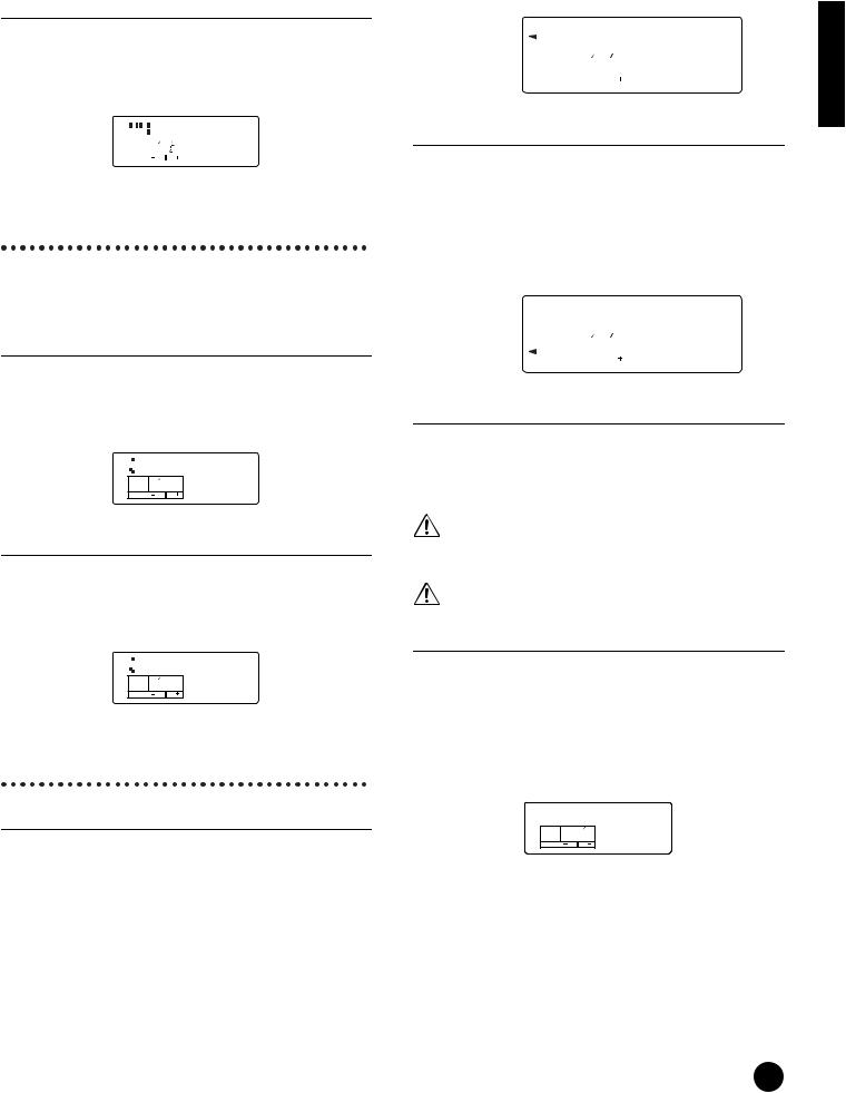
3 Voice Edit Mode (Pages 47, 70)
Press the [EDIT] button in the Voice Play mode. To exit to another mode, simply press the respective button for that mode. Press the [EXIT] button to return to the Voice Play mode.
|
|
|
|
|
GrandPno |
|
|
|
|
|
|
||
|
|
|
|
|
|
|
|
PAGE |
PART ELEM KEY |
XG001 |
|||
|
1 |
|
E |
|||
|
OCTAVE |
|
|
|||
Job Modes
Each Play mode features a separate Job mode. You can select the desired Job mode when the appropriate Play mode lamp, [MULTI] or [VOICE], is lit.
4 Multi Job Mode (Page 67)
Press the [JOB] button in Multi Play mode. To exit to another mode, simply press the respective button for that mode. Press the [EXIT] button to return to the Multi Play mode.


 Init
Init
PAGE PART ELEM KEY multi
1
OCTAVE
4 Voice Job Mode (Page 87)
Press the [Job] button in Voice Play mode. To exit to another mode, simply press the respective button for that mode. Press the [EXIT] button to return to the Voice Play mode.


 Init
Init
PAGE PART ELEM KEY voice
1
OCTAVE
Other Modes
5 Utility Mode (Page 90)
Press the [UTILITY] button to enter the Utility Mode. To exit to another mode, simply press the respective button for that mode. If one of the Play mode lamps ([MULTI] or [VOICE]) is lit, the corresponding Play mode is still active, even while entering this mode. An arrow appears in the upper left of the LCD, pointing to “UTILITY” on the panel, indicating the Utility mode.
|
MasterTune |
||||||||
UTILITY |
|||||||||
|
|
|
|
|
|
|
|
||
MIDI |
|
|
|
|
|
|
+0000 |
||
|
1 |
PART ELEM KEY |
|||||||
|
|
PAGE |
|
||||||
|
|
|
|
|
|
|
|
|
|
|
|
OCTAVE |
|
|
|
|
|
|
|
6 MIDI Mode (Page 93)
Press the [MIDI] button to enter the MIDI mode. To exit to another mode, simply press the respective button for that mode. If one of the Play mode lamps ([MULTI] or [VOICE]) is lit, the corresponding Play mode is still active, even while entering this mode. An arrow appears in the lower left of the LCD, pointing to “MIDI” on the panel, indicating the MIDI mode.
|
Device No |
|||||||
UTILITY |
||||||||
MIDI |
|
|
|
|
|
|
all |
|
|
1 |
PART ELEM KEY |
||||||
|
|
PAGE |
|
|||||
|
|
|
|
|
|
|
|
|
|
|
OCTAVE |
|
|
|
|
|
|
7 Demo Mode (Page 16)
Press the [DEMO] button (the LED lights) to enter the Demo mode. To exit from the Demo mode and switch to the Multi or Voice Play mode, press the [EXIT], [MULTI] or [VOICE] button.
At the “Demo” screen, any data in the instrument’s User Voice memory will be overwritten by the data for the demo song. Important data should be saved to the external MIDI device or computer beforehand.
At the “DEMO” screen, the Master Tune parameter (in Utility) will be overwritten and set to “0.”
8 Store Mode (Pages 69, 89)
Pressing the [STORE] button in the Multi or Voice mode enters the Store mode where you can store Multis or Voices. The Play mode lamp ([MULTI] or [VOICE]) remains lit, even when entering this mode. To exit to another mode, simply press the corresponding mode’s button. Pressing the [EXIT] button exits from the Store mode.
Store
PAGE PART ELEM KEY MLT01
OCTAVE
Section Basics
29
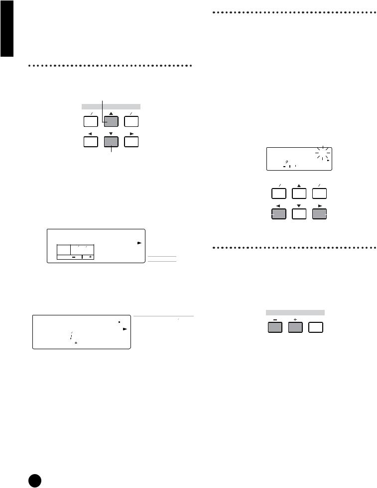
Basics Section
Selecting a Screen
You can switch between screens by using the [▲]/[▼], [E]/[F], [+]/[–] and [EXIT] buttons.
[▲]/[▼] buttons
Many of the displays consist of different screens. Use the [▲]/[▼] buttons to select the various screens.
Previous screen (PAGE)
DATA
DEC NO |
INC YES |
Next screen (PAGE)
When selecting the various display pages, an arrow appears at the right of the LCD, indicating the parameter type in the printed list on the panel. For example, if the display for the Total Volume parameter in the Multi Edit mode is called up, the
arrow in the LCD indicates that this parameter belongs to the General type.
Total Vol |
VOICE |
|||
MIX |
||||
|
|
|
||
PAGE |
PART ELEM KEY |
127 |
GENERAL |
|
TONE |
||||
2 |
P |
|||
CONTROLLER |
||||
OCTAVE
EFFECT
In the example below, the display for the (Element) Cutoff parameter in the Voice Edit mode is shown, and the arrow indicates that this parameter belongs to the Filter type.
Cutoff |
|
|
VOICE |
OSC MIX |
|||||||
|
|
|
|
||||||||
|
MIX |
PITCH |
|||||||||
|
|
|
|
|
|
|
|
|
|
|
|
|
|
|
|
|
|
|
2047 |
GENERAL |
FILTER |
||
|
13 |
|
|
E |
CONTROLLER |
LFO |
|||||
|
PAGE |
PART ELEM KEY |
|
|
|
TONE |
AMP |
||||
|
|
|
|
|
|
|
|
|
|
|
|
|
OCTAVE |
|
|
|
|
|
|
|
|
|
|
|
|
|
|
|
|
|
|
|
|
EFFECT |
EFFECT |
[E]/[F] buttons
Some of the display pages have multiple “screens.” These are indicated by special arrow marks in the top right of the LCD (see below). Use the [E]/[F] buttons to select these pages.
When the first screen of a mulitple-page set is called up, the arrow points to the right (fi), indicating further screens are available. When a page in the middle of the set is called up, arrows point in both directions (‹ fi), indicating you can select either the next or previous screens. When the last screen is called up, the arrow points to the left (‹), indicating no further screens are available.
For certain parameters (such as Voice Name, etc.), these buttons are used to move the cursor position in the display.
Decay Tm 
|
|
|
12 |
1 |
|
+00 |
|
|
||
|
|
|
|
PAGE |
PART ELEM KEY |
|
|
|
|
|
|
|
|
|
|
|
|
|
|
|
|
|
|
|
|
OCTAVE |
|
|
|
|
|
|
|
|
|
|
|
|
|
|
|
|
|
|
|
|
|
|
DATA |
|
|
|
|
|
|
|
DEC NO |
INC YES |
|||||||
Selects the |
|
|
|
|
|
Selects the |
||||
previous screen. |
|
|
|
|
|
|
|
|
next screen. |
|
[+]/[–] buttons
In the Multi Edit mode, these buttons are used to select each part. To select the Common parameters, press both buttons simultaneously. In the Voice Edit mode, these buttons are used to select each Element. To select the Common parameters, press both buttons simultaneously.
PART ELEMENT
 KEY
KEY
MUTE
 COMMON
nFor details on the parameters and page configurations of the Multi Edit and Voice Edit modes, refer to the relevant mode explanations in the Reference section of this manual.
30
 Loading...