


MUSIC SYNTHESIZER
OWNER’S MANUAL
SPECIAL MESSAGE SECTION
PRODUCT SAFETY MARKINGS: Yamaha electronic products may have either labels similar to the graphics shown below or molded/stamped facsimiles of these graphics on the enclosure. The explanation of these graphics appears on this page. Please observe all cautions indicated on this page and those indicated in the safety instruction section.
CAUTION |
RISK OF ELECTRIC SHOCK |
DO NOT OPEN |
CAUTION: TO REDUCE THE RISK OF |
ELECTRIC SHOCK, DO NOT REMOVE |
COVER (OR BACK). NO USER-SERVICEABLE |
PARTS INSIDE. REFER SERVICING TO |
QUALIFIED SERVICE PERSONNEL. |
Battery Notice: This product MAY contain a small non-rechargable battery which (if applicable) is soldered in place. The average life span of this type of battery is approximately five years. When replacement becomes necessary, contact a qualified service representative to perform the replacement.
Warning: Do not attempt to recharge, disassemble, or incinerate this type of battery. Keep all batteries away from children. Dispose of used batteries promptly and as regulated by applicable laws. Note: In some areas, the servicer is required by law to return the defective parts. However, you do have the option of having the servicer dispose of these parts for you.
Disposal Notice: Should this product become damaged beyond repair, or for some reason its useful life is considered to be at an end, please observe all local, state, and federal regulations that relate to the disposal of products that contain lead, batteries, plastics, etc.
The exclamation point within the equilateral triangle is intended to alert the user to the presence of important operating and maintenance (servicing) instructions in the literature accompanying the product.
The lightning flash with arrowhead symbol, within the equilateral triangle, is intended to alert the user to the presence of uninsulated “dangerous voltage” within the product’s enclosure that may be of sufficient magnitude to constitute a risk of electrical shock.
IMPORTANT NOTICE: All Yamaha electronic products are tested and approved by an independent safety testing laboratory in order that you may be sure that when it is properly installed and used in its normal and customary manner, all foreseeable risks have been eliminated. DO NOT modify this unit or commission others to do so unless specifically authorized by Yamaha. Product performance and/or safety standards may be diminished. Claims filed under the expressed warranty may be denied if the unit is/has been modified. Implied warranties may also be affected.
SPECIFICATIONS SUBJECT TO CHANGE: The information contained in this manual is believed to be correct at the time of printing. However, Yamaha reserves the right to change or modify any of the specifications without notice or obligation to update existing units.
NOTICE: Service charges incurred due to lack of knowledge relating to how a function or effect works (when the unit is operating as designed) are not covered by the manufacturer’s warranty, and are therefore the owners responsibility. Please study this manual carefully and consult your dealer before requesting service.
NAME PLATE LOCATION: The graphic below indicates the location of the name plate. The model number, serial number, power requirements, etc., are located on this plate. You should record the model number, serial number, and the date of purchase in the spaces provided below and retain this manual as a permanent record of your purchase.
S80 |
|
|
CARD |
POWER |
AC INLET |
ON OFF |
|
Model |
|
ENVIRONMENTAL ISSUES: Yamaha strives to produce products that are both user safe and environmentally friendly. We sincerely believe that our products and the production methods used to produce them, meet these goals. In keeping with both the letter and the spirit of the law, we want you to be aware of the following:
Serial No.
Purchase Date
92-469- 1 (rear)

PRECAUTIONS
PLEASE READ CAREFULLY BEFORE PROCEEDING
* Please keep these precautions in a safe place for future reference.
 WARNING
Always follow the basic precautions listed below to avoid the possibility of serious injury or even death from electrical shock, short-circuiting, damages, fire or other hazards. These precautions include, but are not limited to, the following:
•This instrument contains no user-serviceable parts. Do not attempt to disassemble or modify the internal components in any way.
•Do not expose the instrument to rain, use it near water or in damp or wet conditions, or place containers on it containing liquids which might spill into any openings.
•If the power cord or plug becomes frayed or damaged, or if there is a sudden loss of sound during use of the instrument, or if any unusual smells or smoke should appear to be caused by it, immediately turn off the power switch, disconnect the electric plug from the outlet, and have the instrument inspected by qualified Yamaha service personnel.
•Only use the voltage specified as correct for the instrument. The required voltage is printed on the name plate of the instrument.
•Always connect the three-pin attachment plug to a properly grounded power source. (For more information about the main power supply, see page 12.)
•Before cleaning the instrument, always remove the electric plug from the outlet. Never insert or remove an electric plug with wet hands.
•Check the electric plug periodically and remove any dirt or dust which may have accumulated on it.
 CAUTION
Always follow the basic precautions listed below to avoid the possibility of physical injury to you or others, or damage to the instrument or other property. These precautions include, but are not limited to, the following:
•Do not place the power cord near heat sources such as heaters or radiators, and do not excessively bend or otherwise damage the cord, place heavy objects on it, or place it in a position where anyone could walk on, trip over, or roll anything over it.
•When removing the electric plug from the instrument or an outlet, always hold the plug itself and not the cord. Pulling by the cord can damage it.
•Do not connect the instrument to an electrical outlet using a multiple-connector. Doing so can result in lower sound quality, or possibly cause overheating in the outlet.
•Remove the electric plug from the outlet when the instrument is not to be used for extended periods of time, or during electrical storms.
•Before connecting the instrument to other electronic components, turn off the power for all components. Before turning the power on or off for all components, set all volume levels to minimum. Also, be sure to set the volumes of all components at their minimum levels and gradually raise the volume controls while playing the instrument to set the desired listening level.
•Do not expose the instrument to excessive dust or vibrations, or extreme cold or heat (such as in direct sunlight, near a heater, or in a car during the day) to prevent the possibility of panel disfiguration or damage to the internal components.
•Do not use the instrument near other electrical products such as televisions, radios, or speakers, since this might cause interference which can affect proper operation of the other products.
•Do not place the instrument in an unstable position where it might accidentally fall over.
•Before moving the instrument, remove all connected cables.
•When cleaning the instrument, use a soft, dry cloth. Do not use paint thinners, solvents, cleaning fluids, or chemical-impregnated wiping cloths. Also, do not place vinyl, plastic or rubber objects on the instrument, since this might discolor the panel or keyboard.
•Do not rest your weight on, or place heavy objects on the instrument, and do not use excessive force on the buttons, switches or connectors.
•Use only the stand specified for the instrument. When attaching the stand or rack, use the provided screws only. Failure to do so could cause damage to the internal components or result in the instrument falling over.
•Do not operate the instrument for a long period of time at a high or uncomfortable volume level, since this can cause permanent hearing loss. If you experience any hearing loss or ringing in the ears, consult a physician.
■REPLACING THE BACKUP BATTERY
•This instrument contains a non rechargeable internal backup battery which permits internal data to remain stored even when the power is off. When the backup battery needs replacing, the message "Change internal battery." will display in the LCD. When this happens, immediately back up your data, then have qualified Yamaha service personnel replace the backup battery.
•Do not attempt to replace the backup battery yourself, in order to prevent the possible serious hazards. Always have qualified Yamaha service personnel replace the backup battery.
•Never place the backup battery in a location that a child can reach, since a child might accidentally swallow the battery. If this should happen, consult a physician immediately.
■SAVING USER DATA
•Always save data to a Memory Card (SmartMedia) frequently, in order to help prevent the loss of important data due to a malfunction or user operating error.
Yamaha cannot be held responsible for damage caused by improper use or modifications to the instrument, or data that is lost or destroyed.
Always turn the power off when the instrument is not in use.
(2)-6

Introduction
Thank you for purchasing the Yamaha S80 Music Synthesizer.
Your new S80 synthesizer incorporates the highly-acclaimed AWM2 synthesis engine, allowing the creation of super-realistic sounds. You can play these sounds over the 88-note fully-weighted keyboard. It also supports optional Plug-in Boards that provide other synthesis engines of your choice, enabling the production of cutting edge synthesizer sounds.
You can play all these sounds using the synthesizer’s automatic playback facilities such as the built-in Arpeggiator and Sequencer. The Quick Access feature lets you access various genres of sounds quickly and directly via the front panel.
Other features include Effects and Control Sets (for controlling various sound parameters in real time using different controllers.) These features make this synthesizer ideal for every kind of live performance or studio work.
When editing a sound, you can use the [PAGE] knob to switch between screens and five other knobs plus the [DATA] knob for changing parameter values. This makes the process of editing sounds much easier and smoother. To make the most use of your synthesizer, you are encouraged to read through this manual. After reading the manual, please keep it in a convenient and safe place for future reference.
About This Manual
This manual is basically divided into two sections:
■Basics Section (Page 6)
Explains how to get started with the synthesizer, its overall structure, and how to use its main features and functions.
■Reference Section (Page 64)
Explains the parameters in the synthesizer’s various Modes.
Package Contents
•Owner’s Manual (this book)
•Data List
•Performance List
•AC Power cord
•Installation Guide
•CD-ROM
The Included CD-ROM
Application software for your synthesizer included on this CD-ROM. The Voice Editor application lets you edit your synthesizer's sounds through a graphical user interface. The Card Filer application lets you exchange data between your synthesizer and computer. Details are given in the separate Installation Guide or the on-line manuals included with the software.
Never attempt to play back the track1, in which the application software is located, on an audio CD player. Doing so may result in damage to your hearing as well as to your CD player/audio speakers.
Copying of the commercially available music sequence data and/or digital audio files is strictry prohibited except for your personal use.
The illustrations and LCD screens as shown in this owner’s manual are for instructional purposes only, and may appear somewhat different from those on your instrument.
The company names and product names in this Owner’s Manual are the trademarks or registered trademarks of their respective companies.
4

Table of Contents
Basics Section |
|
The Controls & Connectors ................................ |
6 |
Before Use ........................................................ |
12 |
Power Supply ........................................................ |
12 |
Connections .......................................................... |
13 |
Powering Up.......................................................... |
19 |
Basic Operations .............................................. |
21 |
Selecting a Mode .................................................. |
21 |
Selecting a Screen ................................................ |
23 |
Entering Data........................................................ |
24 |
Demo Playback ................................................ |
26 |
Voices and Performances .................................. |
27 |
Playing a Voice...................................................... |
27 |
Playing a Performance.......................................... |
29 |
An Overview of the S80 .................................. |
31 |
Controller Section ................................................ |
31 |
Sequencer Section ................................................ |
31 |
Tone Generator Section ...................................... |
32 |
Effects Section ...................................................... |
34 |
About the Modes .............................................. |
35 |
Voices ................................................................ |
36 |
An Overview of Voices/Waves ............................ |
37 |
Waves .................................................................... |
38 |
Performances .................................................... |
39 |
Ideal for Playing Live ...................................... |
40 |
1 Arpeggiator ........................................................ |
41 |
2 Using Controllers .............................................. |
43 |
Voice Edit.......................................................... |
50 |
Effects.................................................................... |
55 |
Using as a Master Keyboard |
|
(Performance Mode) ........................................ |
57 |
Using as a Multitimbral Tone Generator |
|
(Performance Mode) ........................................ |
62 |
Reference Section |
|
Voice Mode........................................................ |
64 |
Voice Play .............................................................. |
64 |
Voice Edit .............................................................. |
68 |
Voice Job Mode .................................................. |
105 |
Voice Store .......................................................... |
106 |
Performance Mode ........................................ |
107 |
Performance Play .............................................. |
107 |
Performance Edit .............................................. |
111 |
Performance Job Mode ...................................... |
130 |
Performance Store .............................................. |
131 |
Sequence Play Mode ...................................... |
132 |
Utility Mode.................................................... |
134 |
Utility Job Mode ................................................ |
141 |
Card Mode ...................................................... |
142 |
Appendix |
|
About the Plug-in Boards (Optional) ............ |
148 |
Display Messages ............................................ |
151 |
Troubleshooting.............................................. |
152 |
Specifications .................................................. |
155 |
Index .............................................................. |
156 |
Basics Section
Reference
Section
Voice Mode
Performance |
Mode |
Sequence Play |
Mode |
Utility Mode |
Card Mode |
Appendix |
5

Basics
Section
Basics Section
The Controls & Connectors
Front Panel |
PITCH bend wheel (Page 43) |
|
Controls the pitch bend effect. You can also assign other functions to this controller.
MODULATION wheel (Page 43)
Controls the modulation effect. You can also assign other parameters functions to this controller.
GAIN ..... A/D INPUT |
|
L/MONO |
R |
1 |
2 |
FOOT |
FOOT |
FOOT |
|
|
|
IN |
OUT |
THRU |
|
|
|
PHONES |
OUTPUT |
|
INDIVIDUAL OUTPUT |
VOLUME CONTROLLER SUSTAIN |
SWITCH |
BREATH |
TO HOST |
HOST SELECT |
|
MIDI |
|
|
|
|
|||
|
|
|
|
|
|
|
|
|
|
|
|
|
|
VOLUME |
CONTROL SLIDER |
|
|
PITCH |
MODULATION |
|
|
|
|
|
|
|
|
|
|
|
|
|
|
|
|
|
|
|
|
|
|
|
|
|
|
|
|
|
|
1 |
2 |
3 |
4 |
[VOLUME] Slider (Page 20)
Adjusts the master volume. Move the slider upwards to raise the output level from the OUTPUT L/R jacks and the PHONES jack.
Control Sliders (Page 61)
In Master Keyboard Mode, the sliders can be used to control various functions assigned to them (as Control Change messages). Each slider controls each of four Zones.
6

Section
Basics
LCD (Liquid Crystal Display)
This is a backlit 2-line display.
|
|
|
|
3.3V CARD |
|
|
|
|
|
|
|
ASSIGNABLE KNOB |
|
|
|
SHIFT |
PAGE |
A |
B |
C |
1 |
2 |
DATA |
|
|
PART/ELEMENT |
|
|
|
|
|
[DATA] knob (Page 25)
Use this to increase or decrease the value of the parameter at which the cursor is positioned.
Knobs [A], [B], [C], [1] and [2] (Page 24)
In each Play Mode, these knobs mainly control the functions respectively assigned to them. In each Edit Mode, each knob is used to enter a value for the associated parameter shown in the display. Depending on the operation or the screen you are working in, these knobs will function differently.
Knobs [A] to [C] can be assigned to system control functions (Pages 46, 136). Knobs [1] and [2] can be assigned control functions that affect Voices (Pages 47, 74).
[PAGE] knob (Page 23)
Switches between screens in each Mode. Each Mode includes several screens.
[SHIFT] key (Page 23)
In Voice or Performance Play Mode, a screen for viewing or setting the Octave parameter and the MIDI Transmit channel (Page 23) is shown when you press the [SHIFT] key. In any of the Edit Modes, when pressing this key while turning the [PAGE] knob, a menu screen is displayed and you can quickly switch between Edit Mode screens (Page 23). If while holding this key you turn one of Knobs [A] ~ [C], [1] ~ [2], [DATA] knob, or press either [INC/YES] or [DEC/NO] key, you can move the cursor without a parameter value being changed (Page 24).
7

Basics
Section
[MASTER KEYBOARD] key (pages 57, 111)
The S80 keyboard can work as MIDI master keyboard in Performance mode. When the key is pressed and switched on (the LED will light), the keyboard can play and control multiple MIDI sound modules connected to the S80.
[EF BYPASS] key (Page 56)
Enables/dsiables the Effect Bypass. Press the key (its LED will light) to bypass the effects used with the current Voice or Performance. The bypassed effects (Reverb, Chorus, or Insertion) are specified in Utility Mode (Page 135).
[EXIT] key (Page 23)
The menus and screens of the S80 have a hierarchical structure. Press this key exit from the current screen and return to the previous level in the hierarchy.
[ENTER] key (Pages 24, 25)
While selecting a Memory or Bank for Voice or Performance, press this key to determine such a memory location. Also, use this key to execute a Job or a Store operation.
[DEC/NO] key (Page 24)
Use this to decrease the value of the parameter at which the cursor is positioned. Also use it to cancel a Job or a Store operation.
[INC/YES] key (Page 24)
Use this to increase the value of the parameter at which the cursor is positioned. Also use it to execute a Job or a Store operation.
MODE keys (Page 21)
Press these to keys to select Voice, Performance, Utility or other Modes.
SEQ controls (Pages 26, 132)
Press the [SEQ PLAY] key to enter Sequence Play Mode. Here, you can play a MIDI file from Memory Card. Use the [PLAY/STOP] key to start or stop playback of the currently selected file.
|
|
|
MODE |
|
|
EF |
MASTER |
VOICE |
PERFORM STORE |
||
BYPASS |
KEYBOARD |
||||
|
|
|
|||
EXIT |
ENTER |
UTILITY |
CARD |
SEQ |
|
PLAY |
|||||
|
|
|
|
||
DEC/NO |
INC/ YES |
EDIT |
JOB |
PLAY/ |
|
STOP |
|||||
|
|
|
|
||
COMPARE |
8
MEMORY keys (Pages 27, 29, 65, 109)
Using one of these keys, you can select a Voice or Performance Memory. Press the [ENTER] key to select the Memory. In Performance Mode, the [EXT], [PLG1] and [PLG2] keys can be used to select the A/D Part, Plug-in 1 Part and Plug-in 2 Part. The [PRE1] and [PRE2] keys select “Common” (for all Parts).
[QUICK ACCESS] key (Page 68)
When you press the [QUICK ACCESS] key (its LED will light), you can use BANK keys [A] to [H] to directly select Categories and PROGRAM keys [1] to [16] to quickly select Voices.
|
|
|
|
|
|
|
AC INLET |
POWER |
|
|
|
|
|
|
|
|
|
ON / |
OFF |
PRE1 |
PRE 2 |
INT |
EXT |
PLG1 |
PLG2 |
|
|
|
|
DRUM |
|
DRUM |
|
|
|
QUICK |
|
|
|
|
|
|
|
|
|
|
ACCESS |
|
|
A |
B |
C |
D |
E |
F |
G |
H |
|
|
A. PIANO |
E. PIANO |
ORGAN |
GTR/BASS |
STRINGS |
BRASS |
SYNTH |
OTHER |
|
|
1 |
2 |
3 |
4 |
5 |
6 |
7 |
8 |
|
|
9 |
10 |
11 |
12 |
13 |
14 |
15 |
16 |
|
|
BANK [A] to [H] keys (Pages 65, 109)
Each key selects a Voice or Performance Bank. Each Bank contains sixteen Voices or Performances. In Voice Edit Mode, each of the BANK [A] to [D] keys selects a Voice’s Element (ELEMENT SELECT) while each of the BANK [E] to [H] keys turns the associated Voice’s Element on or off (ELEMENT ON/OFF) (Page 51). When you activate Master Keyboard Mode by pressing the [MASTER KEYBOARD] key, these key ([A] to [D]) can respectively select Zones 1 to 4 if the Master Keyboard Mode setting is 4 zone in Performance Edit Mode.
PROGRAM/PART [1] to [16] keys (Pages 65, 109)
Each key selects a Voice or Performance from the current Bank. In Voice Edit Mode, each PROGRAM/PART key selects an associated edit menu (Page 70). In Performance Mode, these keys select Parts [1] to [16], respectively.
Section
Basics
9

Basics
Section
Rear Panel
POWER switch (Page 19)
Use this to switch the
synthesizer on or off.
AC INLET terminal (Page 12)
Plug the female end of the supplied AC power cord in here before plugging it into an AC wall outlet.
CARD slot (Page 142)
Insert a Memory Card here to transfer various data to/from the instrument. Read carefully the precautions on use of a Memory Card (Page 142) before using a card.
MIDI IN, OUT, and THRU connectors (Page 15)
MIDI IN receives MIDI messages from an external MIDI device. Use this connector to control the synthesizer from an external MIDI device. MIDI OUT sends out MIDI messages generated by the synthesizer, such as notes played on the keyboard or panel control/knob variations, to an external MIDI sound module or device. MIDI THRU just reflects the MIDI messages received at MIDI IN. Connect other MIDI devices here.
|
|
3.3V CARD |
POWER |
AC INLET |
|
ON |
OFF |
|
FOOT CONTROLLER jack (Pages 18, 44)
An optional foot controller (FC7, etc.) can be connected here. Using the foot controller, you can control tones, pitches, volumes or the like by foot.
FOOT VOLUME jack (Pages 18, 44)
An optional foot controller (FC7, etc.) can be connected here. You can control the output level from the instrument by foot. In Utility Mode, you can select Volume or Expression for this controller.
INDIVIDUAL OUTPUT 1 and 2 jacks (Page 13)
Line level audio signals are output from the synthesizer via these phone jacks (1/4" mono phone plug). The output is separated from that at the OUTPUT L/MONO and R jacks. In Performance Mode, you can specify which Parts can be output from these separate outputs.
10
HOST SELECT switch (Page 16)
Select the type of computer connected to the synthesizer via the TO HOST connector .
TO HOST terminal
Connect a computer here using an optional serial computer cable (Page 16).
BREATH jack (Pages 18, 44)
Connect an optional breath controller BC3 here. You can use the Breath Controller to change the output level or tone of the sounds according to the strength of your breath.
FOOT SWITCH jack (Pages 18, 44)
Connect an optional Foot switch (FC4 or FC5) here. Using the foot switch, you can control of a range of on or off a specific function by foot, as assigned on the instrument. (Pages 53, 165)
SUSTAIN jack (Pages 18, 44)
An optional Foot Switch (FC4 or FC5) can be connected here. You can use the Foot Switch as a damper pedal on the acoustic piano or for a sustained effect.
Section
Basics
|
|
|
|
|
|
|
|
|
|
|
|
|
|
|
|
|
|
|
|
|
|
|
|
|
|
|
|
|
|
|
|
|
|
|
|
|
|
|
|
|
|
|
|
|
|
|
|
|
|
|
|
|
|
|
|
|
|
|
|
|
|
|
|
|
|
|
|
|
|
|
|
|
|
|
|
|
|
|
|
|
|
|
|
|
|
|
|
|
|
|
|
|
|
|
|
|
|
|
|
|
|
|
|
|
|
|
|
|
|
|
|
|
|
|
|
|
|
|
|
|
|
|
|
|
|
|
|
|
|
|
|
|
|
|
|
|
|
|
|
|
|
|
|
|
|
|
|
|
|
|
|
|
|
|
|
|
|
|
|
|
|
|
|
|
INDIVIDUAL OUTPUT |
|
OUTPUT |
|
|
|
|||
|
|
|
|
|
|
|
MIDI |
|
|
|
|
|
|
|
|
FOOT |
|
FOOT |
FOOT |
|
|
|
|
|||||
|
|
|
|
|
|
THRU |
OUT |
IN |
HOST SELECT TO |
HOST BREATH SWITCH |
SUSTAIN CONTROLLER VOLUME |
2 |
1 |
R |
|
L MONO PHONES |
A D INPUT GAIN |
|
||||||||||
|
|
|
|
|
|
|
|
|
|
|
|
|
|
|
|
|
|
|
|
|
|
|
|
|
|
|
|
|
MIDI |
Mac |
PC-2 PC-1 |
|
OUTPUT L/MONO and R jack
(Page 13)
Line level audio signals are output via these phone jacks. For monophonic output, use just the L/MONO jack.
PHONES jack (Page 13)
Connect a pair of headphones
here.
A/D INPUT jack (Page 14)
External audio signals can be input via this phone jack. When an A/D Input Part is used in a Performance, signals from devices connected to this jack can be input in mono.
GAIN knob (Pages 63)
Use this to adjust the input gain of the audio signals at the A/D INPUT jack. You may need to adjust this depending on the type of device (microphone, other instrument output, etc.) connected when using a A/D Input Part.
11

Basics
Section
Before Use
This section explains how to connect to an AC power source, audio and MIDI devices, and a computer system. Only switch the synthesizer on after you have made all the necessary connections.
It is recommended that you read this section before using the synthesizer.
Power Supply
Rear panel
AC INLET terminal
Power cord (included)
1Make sure that the instrument’s POWER switch is at the OFF position.
2Connect the supplied power cord to the AC INLET terminal on the instrument’s rear panel.
3Connect the other end of the power cord to an AC outlet. Make sure the synthesizer meets the voltage requirement for the country or region in which it is being used.
Make sure your S80 is rated for the AC voltage supplied in the area in which it is to be used (as listed on the rear panel). Connecting the unit to the wrong AC supply can cause serious damage to the internal circuitry and may even pose a shock hazard!
Use only the AC power cord supplied with the S80. If the supplied cord is lost or damaged and needs to be replaced, contact your Yamaha dealer. The use of an inappropriate replacement can pose a fire and shock hazard!
The type of AC power cord provided with the S80 may be different depending on the country in which it is purchased (a third prong may be provided for grounding purposes). Improper connection of the grounding conductor can create the risk of electrical shock. Do NOT modify the plug provided with the S80. If the plug will not fit the outlet, have a proper outlet installed by a qualified electrician. Do not use a plug adapter which defeats the grounding conductor.
12
Connections
Connecting to External Audio Equipment
Since the synthesizer has no built-in speakers, you need to monitor its sound output via external audio equipment. Alternatively, you could use a pair of headphones.
There are several methods of connecting to external audio equipment, as described in the following illustrations.
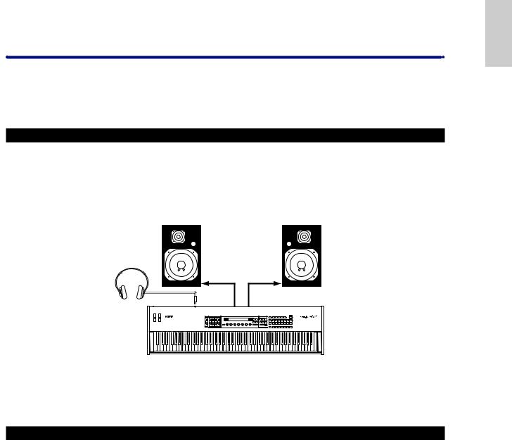
Connecting Stereo Powered Speakers
A pair of powered speakers can accurately produce the instrument’s rich sounds with their own pan and effect settings. Connect your powered speakers to the OUTPUT L/MONO and R jacks on the rear panel.
Powered speaker (Left) |
Powered speaker (Right) |
Headphones
INPUT |
INPUT |
PHONES |
OUTPUT |
OUTPUT R |
|
L/MONO |
|||
|
|
S80
 When using just one powered speaker, connect it to the OUTPUT L/MONO jack on the rear panel.
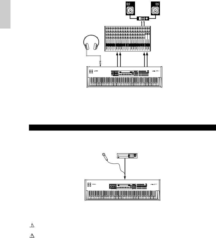
Connecting to a Mixer
There are extra audio outputs in addition to the OUTPUT (L/MONO and R) jacks. These four outputs can connect to a mixer for separately controlling the outputs of up to four Parts in Performance Mode (Page 107). You can specify the output routing of each Part in Performance Edit Mode (Page 111).
Section
Basics
13
Basics
Section
|
|
|
|
|
|
Speaker |
|
|
|
|
|
|
|
|
Amplifier |
|
|
|
|
|
|
L |
|
|
|
R |
|
Mixer |
|
|
|
|
OUTPUT L |
R |
|
|
|
|
|
|
|
|
||
Headphones |
|
|
|
|
|
|
|
|
|
1 2 3 4 5 |
6 |
7 |
8 |
9 |
10 11 12 13 14 15 16 |
L |
R |
|
OUTPUT L / |
|
R |
|
|
INDIVIDUAL |
|
INDIVIDUAL |
PHONES |
MONO |
|
|
|
OUTPUT1 |
|
OUTPUT2 |
|
|
|
|
|
|
||||
S80
 Connecting a pair of headphones does not affect audio output from the OUTPUT (L/MONO and R) jacks.
You can monitor the same sounds via headphones and at the OUTPUT jacks. However, you cannot monitor the sounds from INDIVIDUAL OUTPUT 1 and 2 with headphones.
Connecting a Microphone or Other Audio Equipment
When an A/D Input Part is used in a Performance, signals from devices connected to either of these jacks can be input in mono.
CD Player or other audio equipment (merged to mono internally)
Microphone (mono devices)
A/D INPUT
S80
 After the above connections are complete, you are ready to set up for recording. When starting a recording, you may need to adjust the input gain of the audio source using the GAIN knob. Details about A/D Input, including how to adjust the input gain, are given on Pages 63, 119.
If you choose the wrong type of input source (Pages 119, 120), you may possibly damage your hearing and/or any connected audio equipment. Make sure you set this parameter correctly.
Before connecting a device to the A/D INPUT jack, always turn the GAIN knob all the way down.
 You can connect an external audio source to the A/D Input Part and use it as a Part in a Performance. Details are given on Pages 63, 119.
14

Connecting External MIDI Equipment
You can connect an external MIDI device using a MIDI cable (available separately) and control it from this synthesizer. You can also use an external MIDI keyboard or sequencer to control the synthesizer’s internal sounds. This section introduces several different applications of MIDI.
 The HOST SELECT switch on the rear panel should be set to “MIDI.” Otherwise, MIDI information will not be transmitted from the synthesizer’s MIDI OUT connector.
Controlling from an External MIDI Keyboard
HOST SELECT
PC-2 PC-1
MIDI 
 Mac
Mac
MIDI OUT |
MIDI IN |
|
|
|
|
|
|
|
|
|
|
|
|
|
|
|
|
|
|||||||
|
|
|
|
|
|
|
|
|
|
|
|
|
External MIDI keyboard or synthesizer
S80
Controlling an External MIDI Keyboard
HOST SELECT
PC-2 PC-1
MIDI 
 Mac
Mac
|
|
|
|
|
MIDI OUT |
MIDI IN |
|||
|
|
|
|
|
|||||
|
|
|
|
|
|||||
|
|
|
|
|
|
|
|
|
|
External MIDI keyboard
or synthesizer
S80
Recording and Playback using an External MIDI Sequencer
HOST SELECT
PC-2 PC-1
MIDI 
 Mac
Mac
MIDI OUT |
MIDI IN |
MIDI IN |
MIDI OUT |
|
External MIDI |
S80 |
sequencer |
Section
Basics
15

Basics
Section
Controlling Another MIDI Device via MIDI THRU
External MIDI |
|
sequencer |
External MIDI |
|
synthesizer |
MIDI OUT |
MIDI IN |
MIDI IN |
MIDI THRU |
HOST SELECT |
|
PC-2 PC-1 |
MIDI OUT MIDI IN |
MIDI Mac |
|
External MIDI synthesizer
S80
With the above MIDI connections, you can send MIDI data from the MIDI OUT connector while MIDI data from the external sequencer can be sent to an external MIDI synthesizer via the MIDI THRU jack.
 The MIDI cable should be no greater than 15 meters in length, and there should be no more than three devices in a MIDI chain (chained in series via each unit’s MIDI THRU). To connect more units, use a MIDI Thru Box for parallel connections. You may encounter errors if the MIDI cables are too long or if too many devices are chained together via their MIDI THRU connectors.
Connecting to a Personal Computer
When a computer is connected, it can be used to control the synthesizer and to transfer synthesizer data to/from computer via MIDI. With the included Voice Editor program, for instance, you can edit the synthesizer’s Voices. Using another program – Card Filer – you can transfer files between the computer and the Memory Card inserted in the synthesizer’s CARD slot.
There are two ways to connect your synthesizer to a computer:
1:Serial connection (the computer’s serial port to the synthesizer’s TO HOST terminal)
2:MIDI connection (the computer’s MIDI interface or external MIDI interface to the synthesizer’s MIDI IN and OUT)
Different computers require different connections, as follows.
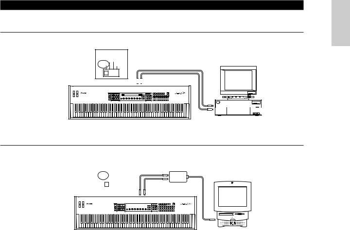
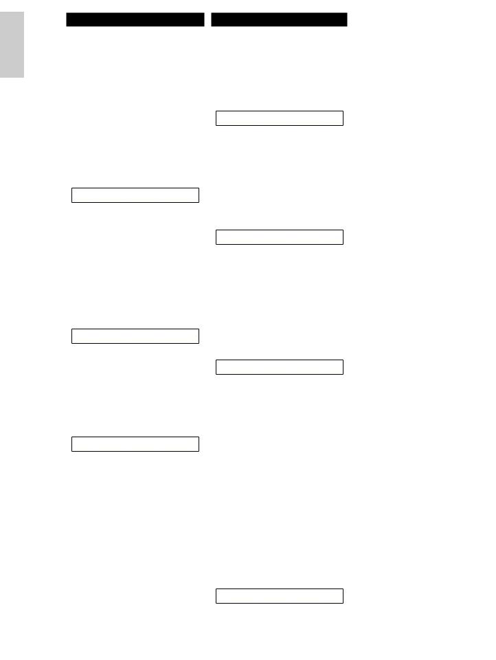
1: Serial Port to TO HOST
IBM PC/AT
HOST SELECT |
|
||||||
PC-2 PC-1 |
|
||||||
MIDI |
|
|
|
Mac |
Serial cable |
||
|
|
|
|
|
|
|
TO |
|
|
|
|
|
|
|
|
|
|
|
|
|
|
|
HOST |
|
|
|
|
|
|
|
|
PS/V |
Personal System/V |
IBM |
Personal System/V |
RS-232C
(DB9)  IBM PC/AT and compatibles
|
|
|
|
|
|
|
|
|
S80 |
|||||||||
Macintosh |
|
|
|
|
|
|
|
|
|
|
||||||||
|
|
|
|
|
|
|
|
|
|
|
|
|
||||||
|
HOST SELECT |
|
|
|
|
|
|
|
|
|
|
|||||||
|
PC-2 PC-1 |
|
|
|
|
Serial cable |
||||||||||||
|
MIDI |
|
Mac |
|
|
|
|
|||||||||||
|
|
|
|
|
|
|
|
|
TO |
|||||||||
|
|
|
|
|
|
|
|
|
||||||||||
|
|
|
|
|
|
|
|
|
HOST |
|||||||||
|
|
|
|
|
|
|
|
|
||||||||||
|
|
|
|
|
|
|
|
|
|
|
|
|
|
|
|
|
|
|
|
|
|
|
|
|
|
|
|
|
|
|
|
|
|
|
|
|
|
PS422 Apple Macintosh
S80 (Modem or
Printer port)
16
2: MIDI Interface to MIDI IN and OUT
Using the computer’s MIDI interface
HOST SELECT
PC-2 PC-1
MIDI Mac
Serial cable
MIDI IN 
 MIDI OUT
PS/V |
Personal System/V |
MIDI |
|
|
OUT |
IBM |
Personal System/V |
|
|
MIDI
IN
Computer with MIDI interface
S80
Using an external MIDI interface
HOST SELECT |
|
|
|
|
|
MIDI Interface |
||||||||||||
PC-2 |
PC-1 |
|
|
MIDI OUT |
||||||||||||||
MIDI |
|
Mac |
|
|
|
|
|
|
|
|
|
|
|
|||||
|
|
|
|
|
|
|
|
|
|
|
|
|||||||
|
|
|
|
|
|
|
|
|
|
|
MIDI IN |
|
||||||
|
|
|
|
|
|
|
|
|
||||||||||
|
|
|
|
|
|
|
|
|
|
|
|
|
|
|
|
|
|
|
|
|
|
|
|
|
|
|
|
|
|
|
|
|
|
|
|
|
|
|
|
|
|
|
|
|
MIDI IN |
MIDI OUT |
||||||||||
|
|
|
|
|
|
|
|
|
|
|
|
|
|
|
|
|
|
|
|
|
|
|
|
|
|
|
|
|
|
|
|
|
|
|
|
|
|
|
|
|
|
|
|
|
|
|
|
|
|
|
|
|
|
|
|
|
Computer
S80
 You will need to an appropriate MIDI application (sequencer, editor, etc.) for your computer platform.
Section
Basics
17

Basics
Section
Connecting Various Controllers
The S80 has several controller jacks on the rear panel, including FOOT SWITCH, SUSTAIN, FOOT CONTROLLER, FOOT VOLUME and BREATH. You can connect optional controllers like a Foot Switch (the FC4 or FC5), Foot Controller (the FC7) and Breath Controller (BC3, etc.) to control tone, volume, pitch and other parameters.
 Details about how to these controllers are given on Page 44.
|
MIDI |
|
FOOT |
FOOT |
FOOT |
INDIVIDUAL OUTPUT |
|
OUTPUT |
|
|
|
THRU |
OUT |
IN |
HOST SELECT TO HOST BREATH SWITCH |
SUSTAIN CONTROLLER VOLUME |
2 |
1 |
R |
L MONO PHONES |
A D INPUT GAIN |
||
MIDI 
 Mac
Mac
PC-2 PC-1
|
|
|
|
|
|
|
|
|
|
|
|
|
|
|
|
|
|
|
|
|
|
|
|
|
|
|
|
|
|
|
BREATH |
|
|
|
|
|
FOOT |
FOOT |
|
|
FOOT |
|
SUSTAIN |
||||||
|
|
|
SWITCH |
|
|
CONTROLLER |
VOLUME |
||
|
|
|
|
|
|
|
|
|
|
BC3 |
FC4 |
FC4 |
FC7 |
FC7 |
|
or |
or |
|
|
|
FC5 |
FC5 |
|
|
18

Powering Up
Power-on Procedure
When you have made all the necessary connections between your synthesizer and any other devices, make sure that all volume settings are turned down all the way to zero. Then turn on the every device in your setup in the order of MIDI masters (senders), MIDI slaves (receivers), then audio equipment (mixers, amplifiers, speakers, etc.). This ensures the smooth flow of signals from the first device to the last (first MIDI, then audio).
When powering down the setup, first turn down the volume for each audio devices, then switch off each device in the reverse order (first audio devices, then MIDI).
When the S80 as MIDI receiver:
POWER
ON!!
|
|
|
|
|
|
|
|
|
|
|
|
|
|
|
|
|
|
|
|
|
|
|
|
|
|
|
|
|
|
|
|
|
|
|
|
|
|
|
|
|
|
|
|
|
|
|
|
|
|
|
|
|
|
|
|
|
|
|
|
|
|
|
|
|
|
|
|
|
|
|
|
|
|
|
|
|
|
|
|
|
|
|
|
|
|
|
MIDI sender |
|
|
|
|
|
|
|
|
|
S80 |
|
|
|
Audio equipment (first mixer, then amplifier) |
||||||||||||||||||||||||||||||||||||||||||||||||||||||||||||||||||
|
|
|
|
|
|
|
|
|
|
|
|
|
|
|
(MIDI receiver) |
|
|
|
|
|
|
|
|
|
|
|
|
|
|
|
|
|
|
|
|
|
|
|
|
|
|
|
|
|
|
|
|
|
|
|
|
|
|
|
|
|
|
|
|
|
|
|
|
|
|
|
|
|
|
|
|
|
|
|
|
||||||||
Switching the S80 On
 Before you switch your synthesizer on or off, first turn down the volume of any audio equipment connected to it.
1Press the POWER switch.
POWER |
AC INLET |
ON OFF
2A splash screen is displayed briefly.
3The Voice or Performance Play Mode screen appears next.
VCE Play) PRE1:001(A01)[Sq:Generation] |
|
EQLow-Q EQMid-G EQHi-G FLT-Rez |
HPF |
Section
Basics
19

Basics
Section
If you have a Memory Card inserted in the instrument’s CARD slot or an optional Plug-in Board installed, you may see other screens before the Voice or Performance Play Mode screen is displayed.
If a previously used Memory Card is inserted in the CARD slot, you will see a screen while files in EXT Memory are being loaded.
If a new Memory Card (one never used on the instrument) is inserted in the CARD slot, you will see a screen while a basic file is being created in EXT Memory.
If you have a Plug-in Board installed, you will see a screen that confirms the presence of the Plug-in Board.
 The final screen after the power-on sequence may change depending on the Power On Mode setting available Utility Mode (Page 135).
4Turn up the amplifier’s volume as necessary.
5Adjust the synthesizer's [VOLUME] slider to set an appropriate volume level.
About Memory Cards
You can save various kinds of data - Voice, Performance, Plug-in, Sequence Chain and so on - onto Memory Card. The built-in CARD slot can accept 3.3-volt Memory Cards (SmartMedia).
 Before using a Memory Card, read through precautions on how to handle it (Page 142).
• Formatting a Memory Card
You cannot use a new Memory Card to save files immediately. The card must be formatted in Card Mode (Page 147) beforehand.
• Saving and Loading Data
You can save various kinds of data as files on a formatted Memory Card. Each file on the card can be loaded when required.
You can save and load data such as System, Voice, Performance, Plug-in, Sequence Chain or the like. Since Sequence Chain data is held temporarily in the synthesizer’s buffer memory and will be lost once you switch it off, you need to save such data onto the Memory Card first.
Details about formatting a Memory Card, saving and loading data, and the recognized file types are given on Page 143.
20
Basic Operations
This section gives some basic explanations about operating the synthesizer.
Selecting a Mode
There are several operation Modes — Voice Play Mode, Performance Play Mode, etc. — each of which enables you to work efficiently with the synthesizer’s various functions.
 An overview of each Mode is given on Page 35.
There are separate Play Modes for Voices and Performances. To enter each of these Modes, use the appropriate MODE key ([VOICE] for Voice Play Mode, [PERFORM] for Performance Play Mode). There are also separate Edit and Job Modes for Voices and Performances. To enter Edit or Job Mode, simply press the [EDIT] or [JOB] key while in each respective Play Mode.
Similarly, pressing the [STORE] key in Voice or Performance Mode takes you into Store Mode where you can store Voices or Performances.
Other Modes include Utility Mode where you can specify system settings, Card Mode where you can perform tasks related to the Memory Card, and Sequence Mode where you can play back MIDI song files or create a sequence chain. (Press the [UTILITY] key for Utility Mode, the [CARD] key for Card Mode and the [SEQ PLAY] key for Sequence Mode.)
MODE
 VOICE
VOICE  PERFORM STORE
1 2 8
UTILITY |
CARD |
SEQ |
|
PLAY |
|||
|
|
||
5 |
6 |
7 |
|
EDIT |
JOB |
PLAY/ |
|
STOP |
|||
|
|
34
COMPARE
Play Modes
1 Voice Play Mode (Page 64)
Press the [VOICE] key (its LED will light) to enter Voice Play Mode. To exit to another Mode, simply press the respective key for that Mode.
VCE Play) PRE1:001(A01)[Sq:Generation] |
|
EQLow-G EQMid-G EQHi-G FLT-Rez |
HPF |
2 Performance Play Mode (Page 107)
Press the [PERFORM] key (its LED will light) to enter Performance Mode. To exit to another Mode, simply press the respective key for that Mode.
PFM Play) |
INT:001(A01)[--:Init Perf ] |
EQLow-G EQMid-G EQHi-G ------- ------- |
|
Edit Modes
When in each Play Mode, you can swiftly switch to each respective Edit Mode by simply pressing the [EDIT] key (its LED will light).
3 Voice Edit Mode (Page 68)
Press the [EDIT] key in Voice Play Mode. To exit to another Mode, simply press the respective key for that Mode or press the [EXIT] key to return to Voice Play Mode.
GEN Name) Ctgry |
a-Z |
0-? Cursor |
C 1234 |
|
[Pf:Init Voice] |
3 Performance Edit Mode (Page 111)
Press the [EDIT] key while in Performance Play Mode. To exit to another Mode, simply press the respective for that Mode or press the [EXIT] key to return to Performance Play Mode.
GEN Name) Ctgry |
a-Z |
0-? |
Cursor |
Common |
|
[--:Init |
Perf ] |
Section
Basics
21
Basics
Section
Job Modes
When in each Play Mode, you can swiftly switch to each respective Job Mode by simply pressing the [JOB] key (its LED will light).
4 Voice Job Mode (Page 105)
Press the [JOB] key in Voice Play Mode. To exit to another Mode, simply press the respective key for that Mode or press the [EXIT] key to return to Voice Play Mode.
VCE |
Initialize) |
Job |
Current Voice |
4 Performance Job Mode (Page 130)
Press the [JOB] key while in Performance Play Mode. To exit to another Mode, simply press the respective for that Mode or press the [EXIT] key to return to Performance Play Mode.
PFM |
Initialize) |
Job |
Current Perform |
4 Utility Job Mode (Page 141)
Press the [JOB] key in Utility Mode. To exit to another Mode, press the respective key for that Mode or press the [EXIT] key to return to Utility Mode.
UTIL Factory Set)
Job
Other Modes
5 Utility Mode (Page 134)
Press the [UTILITY] key (its LED will light) to enter Utility Mode. To exit to another Mode, simply press the respective key for that Mode.
MSTR TG) |
Vol |
NoteShift |
Tune |
Sys |
127 |
+63 |
+102.3c |
6 Card Mode (Page 142)
Press the [CARD] key (its LED will light) to enter Card Mode. To exit to another Mode, simply press the respective key for that Mode.
Save) |
Type |
File |
A-? |
Cursor |
Card |
all |
***[NEWFILE .S2A] |
|
|
7 Sequence Play Mode (Page 132)
Press the [SEQ PLAY] key (its LED will light) to enter Sequence Play Mode. To exit to another Mode, simply press the respective key for that Mode.
SEQ) |
File:[ |
] |
Perf |
Chain00 |
001 ⁄= 120 |
Meas=001 INT:128 |
|
 When MIDI system exclusive messages are received from an external MIDI device, the LED for the currently selected Play Mode (VOICE or PERFORM) will blink.
8 Store Modes (Pages 106, 131)
When in each Play or Edit Mode, you can swiftly switch to each respective Store Mode by simply pressing the [STORE] key. To exit to another Mode, simply press the respective key for that Mode or press the [EXIT] key to return to Play Mode.
VCE |
[Sq:Generation] >[Pf:Slamming ] |
Store |
INT:001(A01) |
22

Selecting a Screen
You can switch between screens using the [PAGE] knob and pressing [SHIFT], [PROGRAM/PART], [EXIT] and [ENTER] keys.
[PAGE] Knob
Usually, there are several screens and sub-screens in each Mode. Use the [PAGE] knob to switch between screens.
VCE Srch) PRE1:
Memory
Some Modes have more screens. In this case, you can use the [PAGE] knob while holding down the [SHIFT] key to switch to a specific screen.
For example, if you use the [PAGE] knob while hoilding down the [SHIFT] key in Voice Edit Mode, the following screen is shown. Select a specific item using the cursor (≥), then release the [SHIFT] key to switch to the parameter screen for that item.
Cursor
GENíOther) Com:>GEN≥QED>ARP>CTL>LFO>EFF
EL1234 Elem:>OSC>PCH>FLT>AMP>LFO>EQ
SHIFT |
PAGE |
A |
B |
C |
1 |
2 |
DATA |
PART/ELEMENT
SHIFT |
PAGE |
A |
B |
Previous screen |
Next screen |
As shown below, the “ ” indicator is displayed to the left of the screen if there are more screens before and after that which you are currently viewing.
At the first in a series of screens, you will see the “ ” indicator meaning that there are more screens to follow, but none before it. At the last screen, you will see the “ ” indicator meaning that there are no more screens to follow.
Indicator

 LFO Depth)
EL1234
 The [SHIFT] key also has other functions, as described in other sections in this manual.
PROGRAM/PART keys
In Voice Edit Mode, PROGRAM/PART keys can be used to select the items shown under the keys and to switch to their screens.
1 |
2 |
3 |
4 |
5 |
6 |
7 |
8 |
GENERAL |
QED |
ARPEGGIO |
CONTROL |
COM LFO |
EFFECT |
|
|
9 |
10 |
11 |
12 |
13 |
14 |
15 |
16 |
OSC |
PITCH |
FILTER |
AMPLITUDE |
LFO |
EQ |
PLG |
|
[EXIT] Key
Press the [EXIT] key to move up (exit) in the hierarchical structure and return to the previous screen.
EF MASTER
BYPASS KEYBOARD
[SHIFT] Key
If you hold down the [SHIFT] key in Voice Play Mode, you can modify the parameters on screen as follows.
(Oct= +3) PRE1:128(H16)[Pf:GrandPiano]
(Tch= 1)
SHIFT |
PAGE |
A |
B |
C |
1 |
2 |
DATA |
PART/ELEMENT
EXIT ENTER
DEC/NO INC/YES
 The [EXIT] key also has other more functions, as described in other sections in this manual.
Section
Basics
23

Basics
Section
[ENTER] Key |
|
Moving the Cursor |
|
|
|
||||
Normally, the [ENTER] key is used to apply |
By using a knob ([A], [B], [C], [1] or [2]) while |
||||||||
holding down the [SHIFT] key, you can move the |
|||||||||
parameter settings. In some cases, however, the |
|||||||||
cursor (≥) to the respective parameter on the |
|||||||||
following screen appears prompting you to press |
|||||||||
screen without affecting its value. |
|
|
|||||||
the [ENTER] key. |
|
|
|
||||||
|
|
|
|
|
|
|
|
||
EF |
MASTER |
|
OSCíOut) |
Level |
|
Delay |
InsEF |
|
|
BYPASS |
KEYBOARD |
|
EL1234 |
96 |
|
≥ 0 |
ins2 |
|
|
|
|
SHIFT PAGE |
A |
B |
C |
1 |
2 |
DATA |
|
EXIT |
ENTER |
|
|
|
|
|
|
|
|
|
|
|
PART/ELEMENT |
|
|
|
|
|
|
DEC/NO |
INC/YES |
|
|
|
|
|
|
|
|
EFFíEF1) Ctgry |
Type |
[ENTER] |
|
C 1234 |
MOD |
Tremolo |
to Edit |
 The [ENTER] key has other functions, as described in other sections in this manual.
Entering Data
You can use the knobs to directly alter their respective parameters on the screen. Alternatively, you can also move the cursor (≥) to a parameter and set its value using the [INC/YES] and [DEC/NO] keys, or the [DATA] knob.
[INC/YES] and [DEC/NO] Keys
You can use the [INC/YES] key to increment a parameter setting by one step, or the [DEC/NO] key to decrement it. If you hold down either key, the value is continuously changed.
DEC/NO INC/YES
You can also use these keys to answer “YES” or “NO” when a confirmation message is displayed.
Knobs [A], [B], [C], [1] and [2]
Each parameter in a screen is normally associated with a knob ([A], [B], [C], [1] or [2]) below the display. When you use one of these knobs, the cursor (≥) moves to its respective parameter and you can change its value. For instance, you can use Knob [B] at the following screen to change the Level setting. Turn the knob clockwise to increase the value and anti-clockwise to decrease it.
Moving the Cursor
By pressing the [INC/YES] or [DEC/NO] key while holding down the [SHIFT] key, you can move the cursor between parameters on the screen without affecting their values.
|
|
OSCíOut) |
Level |
|
Delay |
InsEF |
|
|
|
EL1234 |
≥ 96 |
|
0 |
ins2 |
|
SHIFT |
PAGE |
A |
B |
C |
1 |
2 |
DATA |
PART/ELEMENT
|
|
OSCíOut) |
Level |
|
Delay |
InsEF |
|
|
|
EL1234 |
≥ 96 |
|
0 |
ins2 |
|
|
|
|
|
|
|
|
DEC/NO INC/YES |
SHIFT |
PAGE |
A |
B |
C |
1 |
2 |
DATA |
PART/ELEMENT
24

[DATA] Knob
Use this knob to change the value of the parameter at which the cursor is positioned. Turn the knob clockwise to increment the value one click (step) at a time, or turn it anti-clockwise decrement it.
|
|
OSCíOut) |
Level |
|
Delay |
InsEF |
|
|
|
EL1234 |
≥ 96 |
|
0 |
ins2 |
|
SHIFT |
PAGE |
A |
B |
C |
1 |
2 |
DATA |
PART/ELEMENT
Moving the Cursor
Turn the [DATA] knob clockwise or anticlockwise while holding down the [SHIFT] key to move the cursor to a parameter in the screen without affecting its value.
|
|
OSCíOut) |
Level |
|
Delay |
InsEF |
|
|
|
EL1234 |
≥ 96 |
|
0 |
ins2 |
|
SHIFT |
PAGE |
A |
B |
C |
1 |
2 |
DATA |
PART/ELEMENT
[ENTER] Key
Use this key to apply a setting (when it is blinking, for example.). The [ENTER] key is also used when executing a Job or Store operation, as described in other sections of this manual.
EF MASTER
BYPASS KEYBOARD
EXIT ENTER
DEC/NO INC/YES
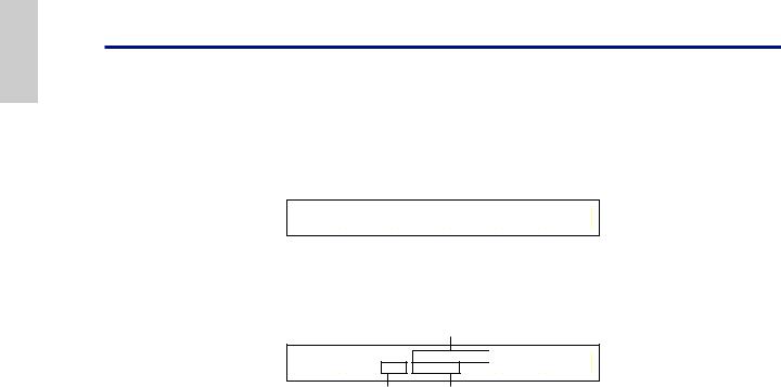
Types of Parameters (Absolute and Relative)
There are many ways to set parameters. Some parameters require you to directly enter numerical settings or alphabetic characters. With others, you can choose from a number of available settings. Furthermore, some types of parameters are “absolute” whereas others are “relative.”
For example, the absolute parameter in the following illustration can be set to either “Mono” or “Poly.” For other absolute parameters such as Volume, the setting can be any value between zero and 127. The Volume setting has a linear, on-to-one relationship with the actual volume, as shown in the graph on the left.
However, relative parameters do not follow the same relationship. The graph on the bottom shows the role of the Velocity Offset parameter. The value you have set here, known as an “offset,” is added to, or subtracted from, the actual value. With Velocity Offset, the specified offset value is added to, or subtracted from, the actual velocity of the notes you play on the keyboard. Sometimes, these types of relative parameters are set as a percentage.
GEN Other) |
Mode |
Assign |
MicroTuning |
|
C 1234 |
poly |
single |
31:Indian |
|
mono/poly |
|
|
|
|
QEDíLevel) |
Vol |
Pan RevSend ChoSend |
||
C 1234 |
127 |
C |
127 |
127 |
|
0~127 |
|
|
|
1Volume (absolute)
Volume
0
127
2 Velocity offset (relative)
Offset |
|
offset added +10 |
|
+64 |
|
||
|
|
|
Actual velocity |
|
|
|
|
0 |
|
|
offset added -10 |
|
|
|
|
|
|
|
|
|
|
Volume |
|
|
|
|
|
-64 |
|
|
|
Section
Basics
25
Basics
Section
Demo Playback
Several demo songs are supplied with this synthesizer. You can play them back as follows.
 Make sure synthesizer is ready for playback. Details are given in the section “Before Use” on Page 12.
 At the “SEQ Demo” screen, any data in the instrument’s internal memory (System, Internal Voices or the like) will be overwritten by the data for the demo song. Important data should be saved to Memory Card (Page 144) beforehand.
1Press the [SEQ PLAY] key to enter Sequence Play Mode. You will see the following screen.
SEQ Demo)<< Are you sure? [YES]/[NO] >>
System,IntVoice will be changed.
 There are two screens in Sequence Play Mode. Use the [PAGE] knob to switch to the screen shown above.
2Press the [INC/YES] key to enter the SEQ Demo screen.
Demo song name
SEQ Demo) Song:[DEMOSONG]
≥ 001 ⁄= 120
Demo song number |
Playback tempo |
 To cancel demo playback, press the [DEC/NO] key.
3Press the [PLAY/STOP] key to start playback of the song.
4Press the [PLAY/STOP] key again to stop playback.
 At the end of the song, playback is automatically looped back to the beginning.
 You can change the playback tempo using the Knob [C]. To use the song’s original tempo, select a tempo value of “***.”
 Details about Sequence Play Mode (and demo playback from Memory Card), are given on Page 132.
26

Voices and Performances
Playing a Voice
Based on an AWM2 synthesis engine, this synthesizer offers various kinds of preset Voices (256 Normal Voices and 8 Drum Voices). You can also create your original Voices and store them into the instrument’s internal memory (INT) or an external Memory Card (EXT). The internal and external memory can each contain up to 128 Normal Voices and 2 Drum Voices. You can freely select and play Voices from both groups of memories, as explained in the following.
|
|
|
|
|
|
|
|
|
|
|
PRE1 |
PRE 2 |
INT |
EXT |
PLG1 |
PLG2 |
|
|
|
|
|
|
|
|
|
|
|
|
MODE |
|
|
|
|
|
|
|
|
|
|
|
|
|
|
|
EF |
MASTER |
|
|
DRUM |
|
DRUM |
|
|
|
QUICK |
|
|
|
|
|
|
|
|
BYPASS |
KEYBOARD |
VOICE |
PERFORM STORE |
|
|
|
|
|
|
ACCESS |
|
|
|
|
|
|
|
|
|
|
|
|
A |
B |
C |
D |
E |
F |
G |
H |
|
|
|
|
|
|
|
EXIT |
ENTER |
UTILITY |
CARD |
SEQ |
|
|
|
|
|
|
|
|
|
|
|
|
|
|
PLAY |
E. PIANO |
ORGAN |
GTR/BASS |
STRINGS |
BRASS |
SYNTH |
OTHER |
||||
|
|
|
|
ASSIGNABLE KNOB |
|
|
|
|
|
|
A. PIANO |
|||||||
|
|
|
|
|
|
|
|
|
|
|
|
|
|
|
|
|
|
|
SHIFT |
PAGE |
A |
B |
C |
1 |
2 |
DATA |
|
|
|
1 |
2 |
3 |
4 |
5 |
6 |
7 |
8 |
|
|
|
|
|
|
|
DEC/NO |
INC/ YES |
EDIT |
JOB |
PLAY/ |
|
|
|
|
|
|
|
|
|
|
|
|
|
|
STOP |
|
|
|
|
|
|
|
||||
|
|
|
|
|
|
|
|
|
|
|
|
|
|
|
|
|
|
|
|
|
|
|
|
|
|
|
|
COMPARE |
|
9 |
10 |
11 |
12 |
13 |
14 |
15 |
16 |
|
|
|
|
|
|
|
|
|
|
|
||||||||
|
|
PART/ELEMENT |
|
|
|
|
|
|
|
|
|
|
|
|
|
|
|
|
3 [DATA] knob |
1 [VOICE] key |
2 MEMORY key |
3 [DEC/NO] and [INC/YES] keys
1 Press the [VOICE] key
The [VOICE] key LED will light, showing that you are now in Voice Play Mode. The following appears in the display.
MODE
 VOICE
VOICE  PERFORM STORE
UTILITY |
CARD |
SEQ |
|
PLAY |
|||
|
|
||
EDIT |
JOB |
PLAY/ |
|
STOP |
|||
|
|
||
COMPARE |
|
|
2 Press a MEMORY key to select a Voice Memory
There are six Voice Memories: PRE1 (Preset 1), PRE2 (Preset 2), INT (Internal), EXT (External), PLG1 (Plug-in 1), and PLG2 (Plug-in 2). Within each Voice Memory are several Banks (up to eight, A to H) in which the Voices are stored. The following illustration shows how Voices are stored in a Voice Memory.
PRE2 (Preset 2) |
EXT (External) |
PLG2 (Plug-in 2) |
Bank A~H |
Bank A~H |
Bank A~D |
1~16 |
1~16 |
1~16 |
Voice |
Voice |
Voice |
VCE Play) PRE1:001(A01)[Pf:StereoGrnd]
EQLow-G EQMid-G EQHi-G ChoSend RevSend
At this point, you can play the Voice (named on the screen) via keyboard.
PRE1 PRE 2 INT EXT PLG1 PLG2
|
|
|
|
|
|
|
|
|
|
|
|
|
|
|
|
|
|
|
|
|
|
|
|
|
|
|
|
|
|
|
|
|
|
|
|
|
|
|
|
|
|
|
|
|
|
|
|
|
|
|
|
|
|
|
|
|
|
|
|
|
|
|
|
|
|
|
|
|
|
|
|
PRE1 (Preset 1) |
INT (Internal) |
|
PLG1 (Plug-in 1) |
||||
Bank A~H |
|
Bank A~H |
|
Bank A~D |
|||
1~16 |
1~16 |
1~16 |
Voice |
Voice |
Voice |
Section
Basics
27

Basics
Section
The Drum Voices are held in separate areas of each Memory, and are accessed as follows.
•To access the Preset Drum Memories (PRE:DR1 ~ DR8):
Press the MEMORY [PRE2] key while holding down the MEMORY [PRE1] key.
•To access the User Drum Memories (INT:DR1/2, EXT:DR1/2):
Press the MEMORY [EXT] key while holding down the MEMORY [INT] key.
|
PRE1 |
PRE 2 |
INT |
|
|
EXT |
|
PLG1 |
PLG2 |
|||||||||
|
|
|
|
|
|
|
|
|
|
|
|
|
|
|
|
|
|
|
|
|
DRUM |
|
|
|
|
|
|
DRUM |
|
|
|
|
|
||||
|
|
|
|
|
|
|
|
|
|
|
||||||||
|
|
|
|
|
|
|
|
|
|
|
||||||||
|
|
|
|
|
|
|
|
|
|
|
||||||||
|
|
|
|
|
|
|
|
|
|
|
|
|
|
|
|
|
|
|
|
|
|
|
|
|
|
|
|
|
|
||||||||
To access Preset Drum Voices |
|
|
To access User Drum Voices |
|||||||||||||||
(PRE:DR1 ~ DR8) |
|
|
|
|
|
|
(INT:DR1/2, EXT:DR1/2) |
|
||||||||||
 PRE1 and PRE2 (Preset 1 and 2) are stored in internal Read Only Memory (ROM) and contain preset Voices which are never overwritten. INT (internal) is stored in Random Access Memory (RAM) and contains the factory default Voices. These can be overwritten, but can be recalled from the original factory settings at any time if required.
 EXT (external) is stored on a Memory Card inserted in the CARD slot. If there is no Memory Card inserted and you attempt to select an EXT Voice, “---
--” will be displayed and no sound will be produced. With a Memory Card inserted, you can select and play EXT Voices. PLG1 or PLG2 Voices can only be selected if a Plug-in Board is installed.
3 Select a Voice Number using the [DATA] knob or the [INC/YES] and [DEC/NO] keys
Turn the [DATA] knob clockwise or press the [INC/YES] key to increment the Voice Number. Turn it anti-clockwise or press the [DEC/NO] key to decrement the Voice Number.
|
|
VCE |
Play) |
PRE1:128(H16)[Pf:GrandPiano] |
|
|||
|
|
EQ |
Low |
EQ Mid |
EQ Hi |
Cutoff RevTime |
|
|
SHIFT |
PAGE |
A |
|
B |
C |
1 |
2 |
DATA |
PART/ELEMENT
EF MASTER
BYPASS KEYBOARD
EXIT ENTER
DEC/NO INC/YES
Now you can play a selected Voice when you play the keyboard.
 Details about selecting Voices using the [DATA] knob or the [DEC/NO] and [INC/YES] keys are given on Page 66.
 You can also select Voices using a combination of BANK and PROGRAM/PART keys, using the Quick Access feature, or using the Category Search feature. Details about selecting Voices are given on Pages 65, 67,68.
Using the Quick Access
Using Quick Access, you can quickly select any of 12 types of Preset Voices and 4 types of Internal Voices (at their factory default settings) in each Bank according to their Categories. The procedure is as follows.
 Details about the Voices that can be selected using Quick Access are given in the separate Data List.
1Press the [QUICK ACCESS] key in Voice Mode. Its LED will light and Quick Access will be enabled.
VCE Quick) INT:017(H01)[Pf:GrandPiano]
EQLow-G EQMid-G EQHi-G FLT-Frq ChoSend
Press the key again or switch to another Mode to disable Quick Access.
 When you enable Quick Access, the Voice you previously selected using Quick Access is selected again.
 If you enable Quick Access while editing a Voice, the Voice is not changed until you select another Voice via Quick Access.
 You cannot use the MEMORY keys while Quick Access is enabled.
2 Use BANK keys [A] to [H] to select the Category. There are eight Categories, as listed below. The Category names are printed below the respective BANK keys.
|
|
|
|
|
|
|
QUICK |
|
|
|
|
|
|
|
ACCESS |
A |
B |
C |
D |
E |
F |
G |
H |
A. PIANO |
E. PIANO |
ORGAN |
GTR/BASS |
STRINGS |
BRASS |
SYNTH |
OTHER |
3 Use PROGRAM keys [1] to [16] to select the Voice within the specified Category. The name of the Voice is displayed.
1 |
2 |
3 |
4 |
5 |
6 |
7 |
8 |
9 |
10 |
11 |
12 |
13 |
14 |
15 |
16 |
 For each BANK [A] to [H], Preset Voices are accessed using PROGRAM keys [1] to [12]. The remaining four keys (PROGRAM keys [13] to [16]) are used to access each of four internal Voices. Details about Voices are given in the separate Data List. By selectively assigning your own selected Voices to the PROGRAM keys [13] to [16] in each BANK, you can make use of the Quick Access feature to quickly switch between them.
28

Playing a Performance
In Performance Play Mode, you can select and play any of 128 internal and 64 external (Memory Card) Performances.
A Performance is a set of Voices used with the built-in (or an external) sequencer. Performances also let you set the synthesizer up for multitimbral operation.
Each Performance can contain up to 16 Parts assigned to different Voices, plus extra Parts for A/D INPUT and Plug-in Boards. If the Layer Switch (Page 123) parameter is switched on for any Parts, those Parts can be play in unison. Also, you can assign multiple Parts to different MIDI channels so that they can be played or be controlled individually using the built-in (or an external) sequencer. Up to 128 Performances can be stored in the internal memory and up to 64 on Memory Card. These Performance settings are available in Performance Edit Mode (Page 111). Here, we will show how to get started with Performance Play after selecting a Performance.
|
|
|
|
|
|
|
|
|
|
|
PRE1 |
PRE 2 |
INT |
EXT |
PLG1 |
PLG2 |
|
|
|
|
|
|
|
|
|
|
|
|
MODE |
|
|
|
|
|
|
|
|
|
|
|
|
|
|
|
EF |
MASTER |
|
|
DRUM |
|
DRUM |
|
|
|
QUICK |
|
|
|
|
|
|
|
|
VOICE |
PERFORM STORE |
|
|
|
|
|
|
ACCESS |
|||
|
|
|
|
|
|
|
BYPASS |
KEYBOARD |
|
|
|
|
|
|
||||
|
|
|
|
|
|
|
|
|
|
|
A |
B |
C |
D |
E |
F |
G |
H |
|
|
|
|
|
|
|
EXIT |
ENTER |
UTILITY |
CARD |
SEQ |
|
|
|
|
|
|
|
|
|
|
|
|
|
|
PLAY |
E. PIANO |
ORGAN |
GTR/BASS |
STRINGS |
BRASS |
SYNTH |
OTHER |
||||
|
|
|
|
ASSIGNABLE KNOB |
|
|
|
|
|
|
A. PIANO |
|||||||
|
|
|
|
|
|
|
|
|
|
|
|
|
|
|
|
|
|
|
SHIFT |
PAGE |
A |
B |
C |
1 |
2 |
DATA |
|
|
|
1 |
2 |
3 |
4 |
5 |
6 |
7 |
8 |
|
|
|
|
|
|
|
DEC/NO |
INC/ YES |
EDIT |
JOB |
PLAY/ |
|
|
|
|
|
|
|
|
|
|
|
|
|
|
STOP |
|
|
|
|
|
|
|
||||
|
|
|
|
|
|
|
|
|
|
|
|
|
|
|
|
|
|
|
|
|
|
|
|
|
|
|
|
COMPARE |
|
9 |
10 |
11 |
12 |
13 |
14 |
15 |
16 |
|
|
|
|
|
|
|
|
|
|
|
||||||||
|
|
PART/ELEMENT |
|
|
|
|
|
|
|
|
|
|
|
|
|
|
|
|
3 [DATA] knob |
1 [PERFORM] key |
2 MEMORY key |
3 [DEC/NO] and [INC/YES] keys
1 Press the [PERFORM] key
The [PERFORM] key LED will light, showing that you are now in Performance Play Mode. The following appears in the display.
MODE
 VOICE
VOICE  PERFORM STORE
UTILITY |
CARD |
SEQ |
|
PLAY |
|||
|
|
||
EDIT |
JOB |
PLAY/ |
|
STOP |
|||
|
|
||
COMPARE |
|
|
PFM Play) |
INT:001(A01)[--:Init |
Perf ] |
||
EQ Low |
EQ Mid |
EQ Hi |
-1 |
+0 |
|
|
|
|
|
2 Press a MEMORY key to select a Performance Memory
There are two Performance Memories: INT (internal) and EXT (External). INT consists of 128 Performances divided into eight Banks (A to H). EXT consists of 64 Performances divided into four Banks (A to D).
PRE1 |
PRE 2 |
INT |
EXT |
|
|
PLG1 |
PLG2 |
|||
|
|
|
|
|
|
|
|
|
|
|
|
DRUM |
|
|
|
DRUM |
|
|
|
|
|
|
|
|
|
|
|
|
|
|
||
|
|
|
|
|
|
|
|
|
||
|
|
|
|
|
|
|
|
|
||
|
|
|
|
|
|
|
|
|
||
|
|
|
|
|
|
|
|
|
||
|
|
|
|
|
|
|
|
|
||
|
|
|
|
|
|
|
|
|
||
|
|
|
|
|
|
|
|
|
|
|
|
INT (Internal) |
|
|
EXT (External) |
|
|||||
|
Bank A~H |
|
|
Bank A~D |
|
|||||
1~16 |
1~16 |
Performance |
Performance |
At this point, you can play the Performance (named on the screen) via keyboard.
 INT (internal) is stored in internal Random Access Memory (RAM) and contains factory default Performances. These can be overwritten but can recalled at any time.
 EXT (external) is stored on a Memory Card (RAM) inserted in the CARD slot. If there is no Memory Card inserted and you attempt to select an EXT Performance, “-----” will be displayed and no sound will be produced. With a Memory Card inserted, you can select and play EXT Performances.
Section
Basics
29

Basics
Section
3 Select a Performance Number using the [DATA] knob or the [INC/YES] and [DEC/NO] keys
Turn the [DATA] knob clockwise or press the [INC/YES] key to increment the Performance Number. Turn it anti-clockwise or press the [DEC/NO] key to decrement the Performance Number.
|
|
PFM Play) |
INT:001(A01)[ |
--:Init Perf ] |
|
||
|
|
EQLow-G EQMid-G |
EQHi-G ------- |
|
------- |
|
|
SHIFT |
PAGE |
A |
B |
C |
1 |
2 |
DATA |
PART/ELEMENT
EF MASTER
BYPASS KEYBOARD
EXIT ENTER
DEC/NO INC/YES
You can now play Parts in the Performance via the keyboard. If the Layer Switch (Page 123) parameter is switched on for any Parts, those Parts can be play in unison. Now try selecting other Performances.
 Details about selecting Performances using the [DATA] knob or the [DEC/NO] and [INC/YES] keys are given on Page 66.
 You can also select Performances using a combination of BANK and PROGRAM/PART keys, or using the Category Search feature. Details about selecting Performances are given on Page 109.
 On selection, a Performance may take a few seconds to become ready since the settings for multiple Parts are applied.
 With some of the Performance presets (INT), you can use Knob [2] to switch the Arpeggiator on/off. Details are given in the separate Performance List.
30
 Loading...