


RX10K
Table of contents
 Loading...
Yamaha RX10K, RX10MK, RX10MSK, RX10RK, RX10RSK Manual
...
OWNER’S MANUAL
SNOWMOBILE
RX10K
RX10MK/RX10MSK
RX10RK/RX10RSK
RXW10K/RXW10SK
8FU-28199-10
LIT-12628-02-37
ESU00286
1-
MACHINE IDENTIFICATION
Identification number records
A. FRAME NUMBER:
CZ-01E
B. ENGINE NUMBER (PRIMARY ID):
CZ-01E
C. KEY NUMBER:
CZ-01E
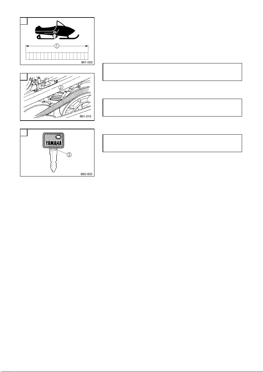
Record the frame number, engine number (Primary ID),
and key number in the spaces provided for assistance
when ordering spare parts from a Yamaha dealer.
1
The
frame number
is the seventeen-digit number
stamped on the frame of the snowmobile. (See
fig.
È
.)
2
The
engine number
is stamped in the location as
shown. (See fig.
É
.)
3
Key number
(See fig.
Ê
.)
Also, record and keep the ID numbers in a separate
place in case the snowmobile is stolen.
A
B
C

ESU00011
2-
INTRODUCTION
Congratulations on your purchase of a Yamaha snowmo-
bile. This model is the result of Yamaha’s vast experience
in the production of fine sporting and touring snowmo-
biles. It represents the high degree of craftsmanship and
reliability that have made Yamaha a leader in these
fields.
This manual will give you an understanding of the opera-
tion, inspection, and basic maintenance of this snowmo-
bile. If you have any questions concerning the operation
or maintenance of your snowmobile, please consult a
Yamaha dealer.
To maintain the high quality and performance of this
snowmobile, it is important that you and your Yamaha
dealer pay close attention to the recommended mainte-
nance schedules and operating instructions contained
within this manual.
RX10K
RX10MK/RX10MSK
RX10RK/RX10RSK
RXW10K/RXW10SK
OWNER’S MANUAL
©2004 by Yamaha Motor Corporation, U.S.A.
1st Edition, April 2004
All rights reserved.
Any reprinting or unauthorized use
without the written permission of
Yamaha Motor Corporation, U.S.A.
is expressly prohibited.
Printed in Japan
P/N LIT-12628-02-37
WARNING
@
PLEASE READ AND UNDERSTAND THIS MANUAL
COMPLETELY BEFORE OPERATING THE SNOWMO-
BILE.
@
NOTE:
@
●
Yamaha continually seeks advancements in product
design and quality. Therefore, while this manual con-
tains the most current product information available
at the time of printing, there may be minor discrepan-
cies between your snowmobile and this manual. If
there is any question concerning this manual, please
consult a Yamaha dealer.
●
This manual should be considered a permanent part
of this snowmobile and should remain with the snow-
mobile when resold.
@
Particularly important information is distinguished in this
manual by the following notations.
The Safety Alert Symbol means ATTENTION! BECOME
ALERT! YOUR SAFETY IS INVOLVED!
WARNING
@
Failure to follow WARNING instructions could result in
severe injury or death to the snowmobile operator, a
bystander, or a person inspecting or repairing the snow-
mobile.
CAUTION
:
@
A CAUTION indicates special precautions that must be
taken to avoid damage to the snowmobile.
NOTE:
@
A NOTE provides key information to make procedures
easier or clearer.

ESU00003
CONTENTS
YAMAHA MOTOR
CORPORATION, U.S.A.
SNOWMOBILE LIMITED
WARRANTY
.......................................1-1
YAMAHA EXTENDED SERVICE
(Y.E.S.)
...............................................1-4
LOCATION OF THE
IMPORTANT LABELS
.......................2-1
SAFETY INFORMATION
...................3-1
DESCRIPTION
...................................4-1
CONTROL FUNCTIONS
....................5-1
Main switch......................................5-1
Starter lever (choke) ........................5-2
Throttle lever....................................5-2
Engine overheating prevention
system .............................................5-2
Throttle override system
(T.O.R.S.) ........................................5-3
Speedometer unit ............................5-4
High beam indicator light .................5-4
Fuel meter and grip/thumb
warmer level indicator......................5-5
Fuel level warning indicator .............5-6
Oil level warning indicator................5-6
Low coolant temperature
indicator light ...................................5-7
Coolant temperature warning
indicator ...........................................5-7
Self-diagnosis warning indicator ......5-8
Engine stop switch.........................5-10
Brake lever ....................................5-10
Parking brake lever........................5-11
Shift lever.......................................5-11
Rear suspension damping force
remote adjustment dial ..................5-12
Headlight beam switch ..................5-12
Shroud latches ..............................5-12
Drive guard....................................5-13
V-belt holders ................................5-13
Carburetor coolant shut-off lever ... 5-13
Storage compartment....................5-14
PRE-OPERATION CHECKS
..............6-1
Fuel .................................................6-1
Engine oil.........................................6-2
Engine oil level ................................6-3
Coolant ............................................6-4
Throttle lever ...................................6-5
Throttle override system
(T.O.R.S.) ........................................6-5
Brake ...............................................6-6
Brake fluid leakage..........................6-7
V-belt ...............................................6-7
Drive guard......................................6-7
Drive track .......................................6-8
51-mm (2.0-in) high-profile
pattern drive track............................6-8
Slide runners ...................................6-9
Skis and ski runners ........................6-9
Steering system.............................6-10
Lights.............................................6-10
Air filter ..........................................6-11
Fittings and fasteners ....................6-11
Tool kit and recommended
equipment......................................6-11
OPERATION
......................................7-1
Starting the engine ..........................7-1
Break-in ...........................................7-2
Riding your snowmobile ..................7-3
Getting to know your snowmobile ...7-3
Learning to ride your snowmobile ...7-3
To start out and accelerate..............7-3
Braking ............................................7-3
Turning ............................................7-4
Riding uphill.....................................7-4
Riding downhill ................................7-5
Traversing a slope...........................7-5

Ice or icy surface .............................7-5
Hard-packed snow...........................7-6
Operation on surfaces other than
snow or ice ......................................7-6
Maximizing drive track life ...............7-7
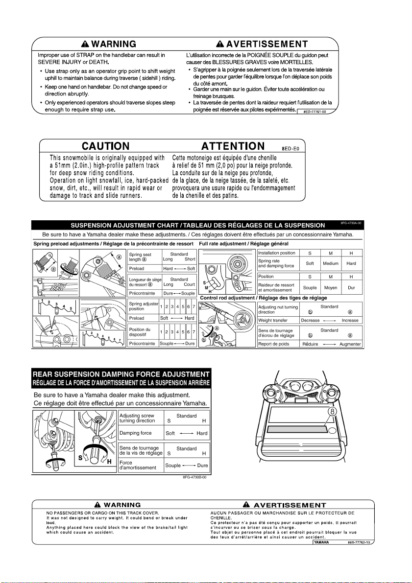
Strap ................................................7-8
Driving .............................................7-9
Stopping the engine.......................7-10
Transporting ..................................7-11
PERIODIC MAINTENANCE ...............8-1
Periodic maintenance chart .............8-1
Tool kit .............................................8-4
Spark plug inspection ......................8-4
Engine idle speed adjustment .........8-6
Throttle cable adjustment ................8-6
Carburetor adjustment.....................8-7
High altitude adjustments ..............8-10
Adjusting the valve clearance........8-10
Changing the engine oil.................8-11
Cooling system ..............................8-13
V-belt replacement ........................8-15
Checking the drive chain
housing oil level and the drive
chain tension .................................8-17
Checking the brake pads...............8-19
Checking the parking brake
pads...............................................8-19
Checking the brake fluid level........8-20
Brake fluid replacement.................8-20
Suspension....................................8-20
Drive track adjustment...................8-29
Ski alignment .................................8-31
Handlebar adjustment ...................8-31
Lubrication .....................................8-34
Headlight bulb replacement...........8-35
Headlight beam adjustment...........8-35
Battery ...........................................8-36
Fuse replacement..........................8-36
TROUBLESHOOTING .......................9-1
STORAGE ........................................10-1
SPECIFICATIONS............................11-1
Dimensions....................................11-1
Engine ...........................................11-2
Chassis..........................................11-2
Electric...........................................11-4
WIRING DIAGRAM ..........................12-1
1-1
ESU00004
1-
YAMAHA MOTOR CORPORATION, U.S.A.
SNOWMOBILE LIMITED WARRANTY
CW-01E
1-2
CW-02E
1-3
CW-03E
1-4
ESU04280
YAMAHA EXTENDED SERVICE (Y.E.S.)
CW-06E
2-1
ESU04050
2-
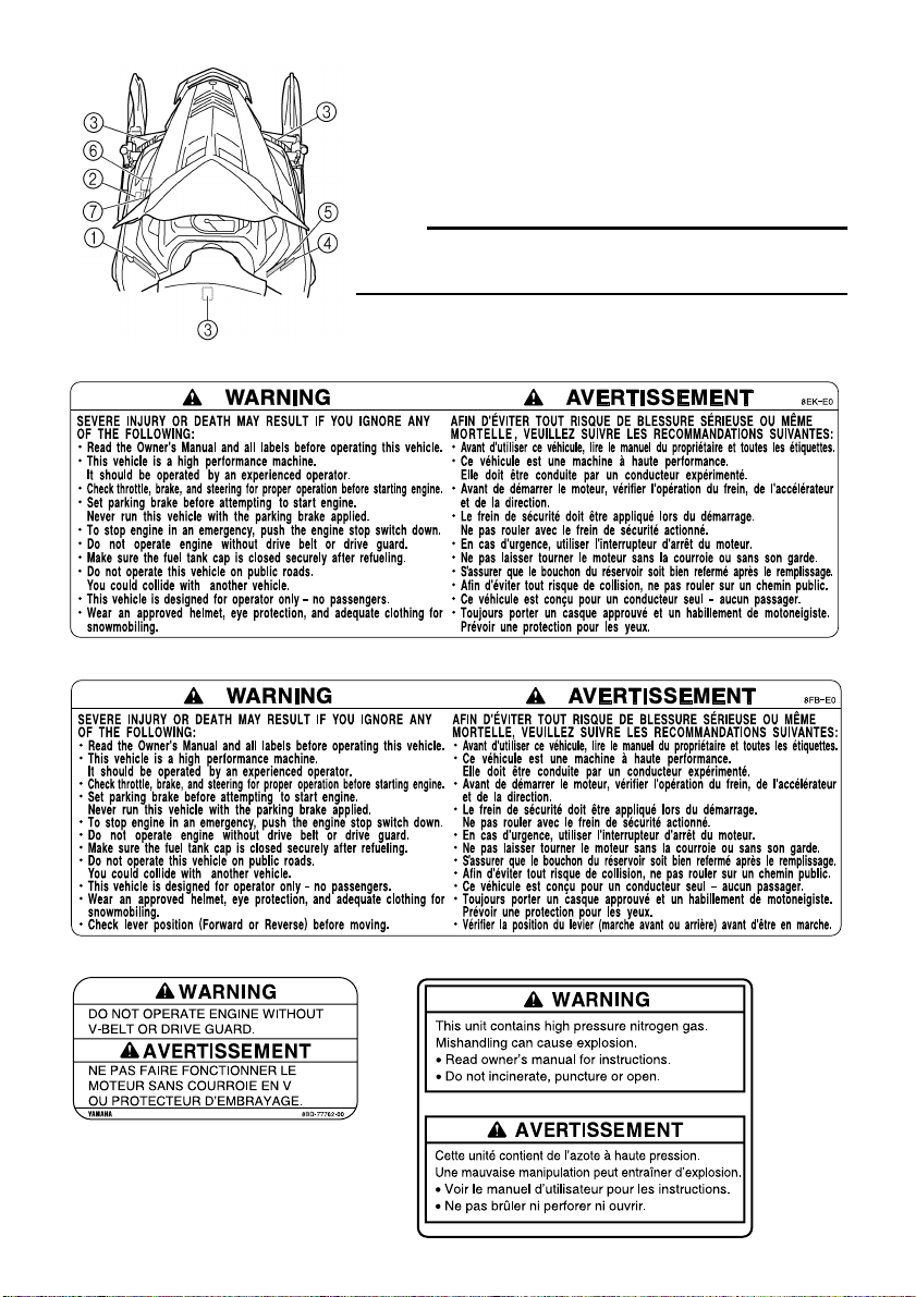
LOCATION OF THE IMPORTANT
LABELS
Please read the following labels carefully before operat-
ing this snowmobile.
NOTE:
@
Maintain or replace safety and instruction labels, as nec-
essary.
@
1
RX10/RX10M/RX10MS
1
RX10R/RX10RS/RXW10/RXW10S
2
3
2-2
4 RX10M/RX10MS
5 RX10M/RX10MS
6 RXW10/RXW10S
7 RXW10/RXW10S
8 RX10M/RX10MS/RXW10/RXW10S
2-3
NOTE:
@
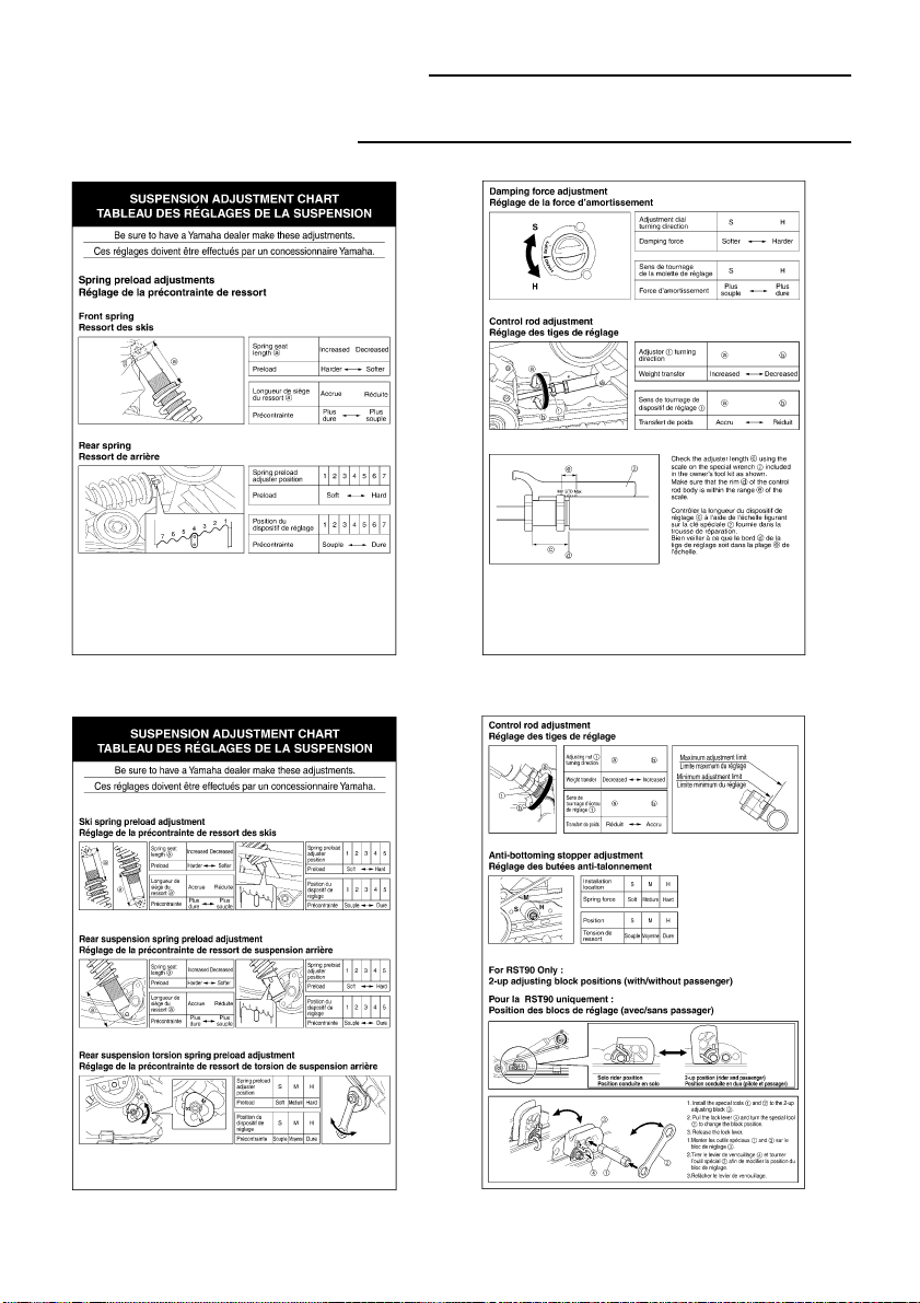
The following suspension adjustment charts are included
with the Owner’s Manual.
@
RX10/RX10R/RX10RS
RX10M/RX10MS
3-1
ESU00008
3-
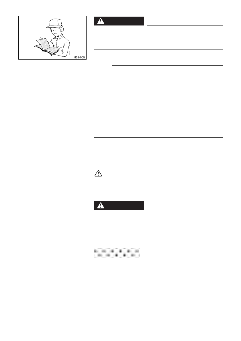
SAFETY INFORMATION
When you ride your snowmobile, you must know and use
the following for your safety. Severe injury or death may
result if you ignore any of the following.
Before operating
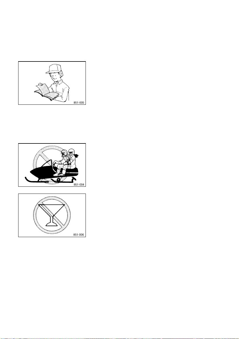
1. Read the Owner’s Manual and all labels before oper-
ating this snowmobile. Become familiar with all of the
operating controls and their function. Consult a
Yamaha dealer about any control or function you do
not understand.
2. This snowmobile was not manufactured for use on
public streets, roads, or highways. Such use is pro-
hibited by law, and you could collide with another
vehicle.
3. This snowmobile is designed to carry the OPERA-
TOR ONLY.
Passengers are prohibited. Carrying a passenger
can cause loss of control.
4. Do not operate the snowmobile after drinking alcohol
or taking drugs. Your ability to operate the snowmo-
bile is reduced by the influence of alcohol or drugs.
5. For safety and proper care of the snowmobile, always
perform the pre-operation checks on pages 6-1–6-11
before starting the engine. Check the throttle, brake,
and steering for proper operation every time before
starting the engine. Make sure that the throttle lever
moves freely and it returns to the home position when
it is released.
6. Apply the parking brake before starting the engine.
Never drive the snowmobile with the parking brake
applied. This may overheat the brake disc and reduce
braking ability.
3-2
7. Do not allow anyone to stand behind the snowmobile
when starting, inspecting, or adjusting the snowmo-
bile. A broken track, track fittings, or debris thrown by
the track could be dangerous to the operator or
bystanders.
8. Handle fuel with care; it is HIGHLY FLAMMABLE.
●
Never add fuel when the engine is running or hot.
Allow the engine to cool for several minutes after
running.
●
Use an approved fuel container.
●
Fill the fuel tank outdoors with extreme care.
Never remove the fuel cap indoors. Never fill the
fuel tank indoors.
●
Never refuel while smoking or in the vicinity of an
open flame.
●
Make sure that the fuel tank cap is closed securely
after refueling. Wipe up any spilled fuel immedi-
ately.
9. If you swallow some gasoline, inhale a lot of gasoline
vapor, or get some gasoline into your eyes, see your
doctor immediately. If any gasoline spills on your skin
or clothing, immediately wash your skin with soap
and water, and change your clothes.
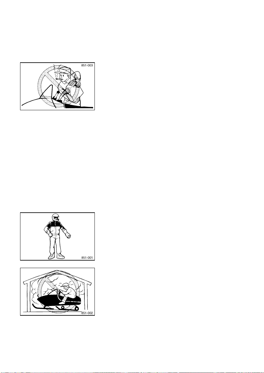
10. Wear protective clothing. Wear an approved helmet,
and a face shield or goggles. Also, wear a good qual-
ity snowmobile suit, boots, and a pair of gloves or mit-
tens that will permit use of your thumbs and fingers
for operation of the controls.
Operation
1. Do not run the engine indoors, except when starting
the engine to transport the snowmobile in or out of
the building. Open the outside doors; exhaust fumes
are dangerous.
2. Be careful where you ride. There may be obstacles
hidden beneath the snow. Stay on established trails
to minimize your exposure to hazards. Ride slowly
and cautiously when you ride off of established trails.
Hitting a rock or stump, or running into wires could
cause an accident and injury.

3-3
3. This snowmobile is not designed for use on surfaces
other than snow or ice. Use on dirt, sand, grass,
rocks, or bare pavement may cause loss of control
and may damage the snowmobile.
4. Avoid operating on glare ice, or on snow which has a
lot of dirt or sand mixed in. Operation under such
conditions will damage or result in rapid wear of ski
runners, drive track, slide runners, and drive sprock-
ets.
5. Always ride with other snowmobilers when going on a
ride. You may need help if you run out of fuel, have an
accident, or damage your snowmobile.
6. Many surfaces such as ice and hard-packed snow
require much longer stopping distances. Be alert,
plan ahead and begin decelerating early. The best
braking method on most surfaces is to release the
throttle and apply the brake gently—not suddenly.
Maintenance and storage
1. Do not leave the snowmobile on its left side for an
extended period of time. Fuel may leak out from the
fuel breather hose.
2. Modifications made to the snowmobile not approved
by Yamaha, or the removal of original equipment may
render your snowmobile unsafe for use that may
cause severe personal injury. Modifications may also
make the snowmobile illegal to use.
3. Never store the snowmobile with fuel in the fuel tank
inside a building where ignition sources are present
such as hot water and space heaters, an open flame,
sparks, clothes dryers, and the like. Allow the engine
to cool off before storing the snowmobile in an
enclosed space.
4. Always refer to the “STORAGE” section if the snow-
mobile is to be stored for an extended period.
5. Maintain or replace safety and instruction labels, as
necessary.
4-1
ESU00012
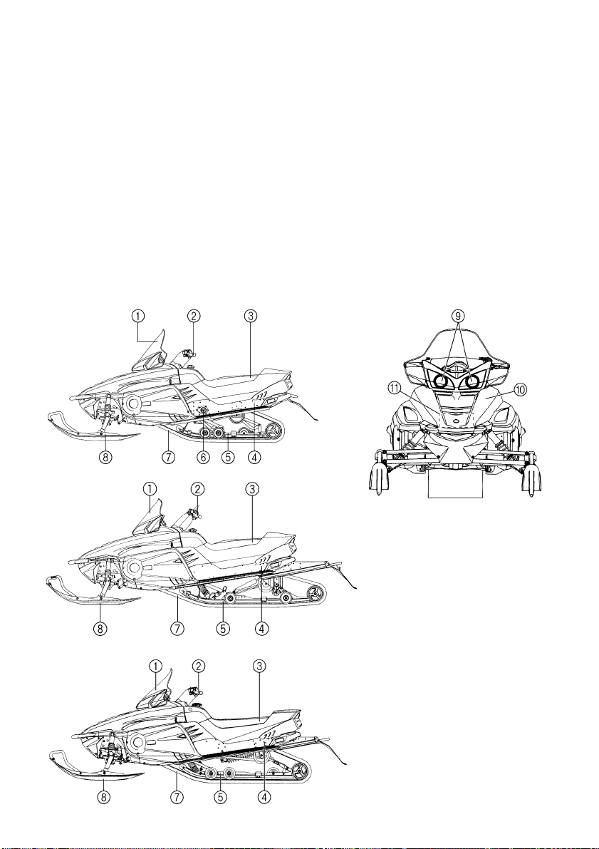
4-
DESCRIPTION
1
Windshield
2
Steering handlebar
3
Seat
4
Frame
5
Slide rail suspension
6
Rear suspension damping force remote
adjustment dial (RX10/RX10R/RX10RS)
7
Drive track
8
Skis
9
Headlights
0
Shroud
A
Storage compartment
RX10/RX10R/RX10RS
RX10M/RX10MS
RXW10/RXW10S
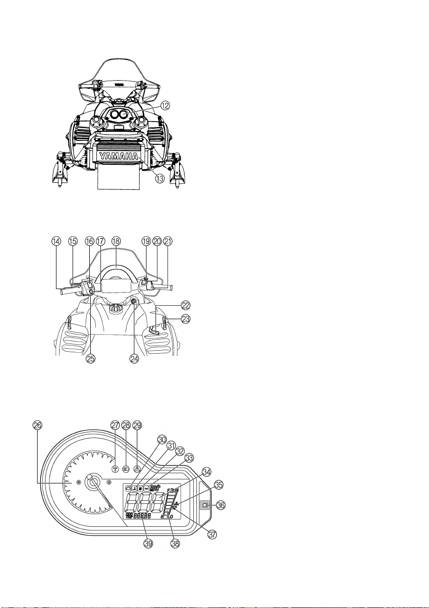
4-2
B
Tail/brake lights
C
Snow flap
D
Brake lever
E
Parking brake lever
F
Grip warmer adjustment switch
G
Headlight beam switch
H
Strap (RX10M/RX10MS)
I
Engine stop switch
J
Thumb warmer adjustment switch
K
Throttle lever
L
Shift lever
(RX10R/RX10RS/RXW10/RXW10S)
M
Shroud latch
N
Main switch
O
Starter lever
P
Tachometer
Q
Low coolant temperature indicator light
R
High beam indicator light
S
Warning light
T
Self-diagnosis warning indicator
U
Coolant temperature warning indicator
V
Fuel level warning indicator
W
Oil level warning indicator
X
Speedometer
Y
Grip warmer indicator
Z
Select/reset button
[
Thumb warmer indicator
\
Fuel meter and grip/thumb warmer level
indicator
]
Odometer/tripmeter
5-1
ESU00013
5-
CONTROL FUNCTIONS
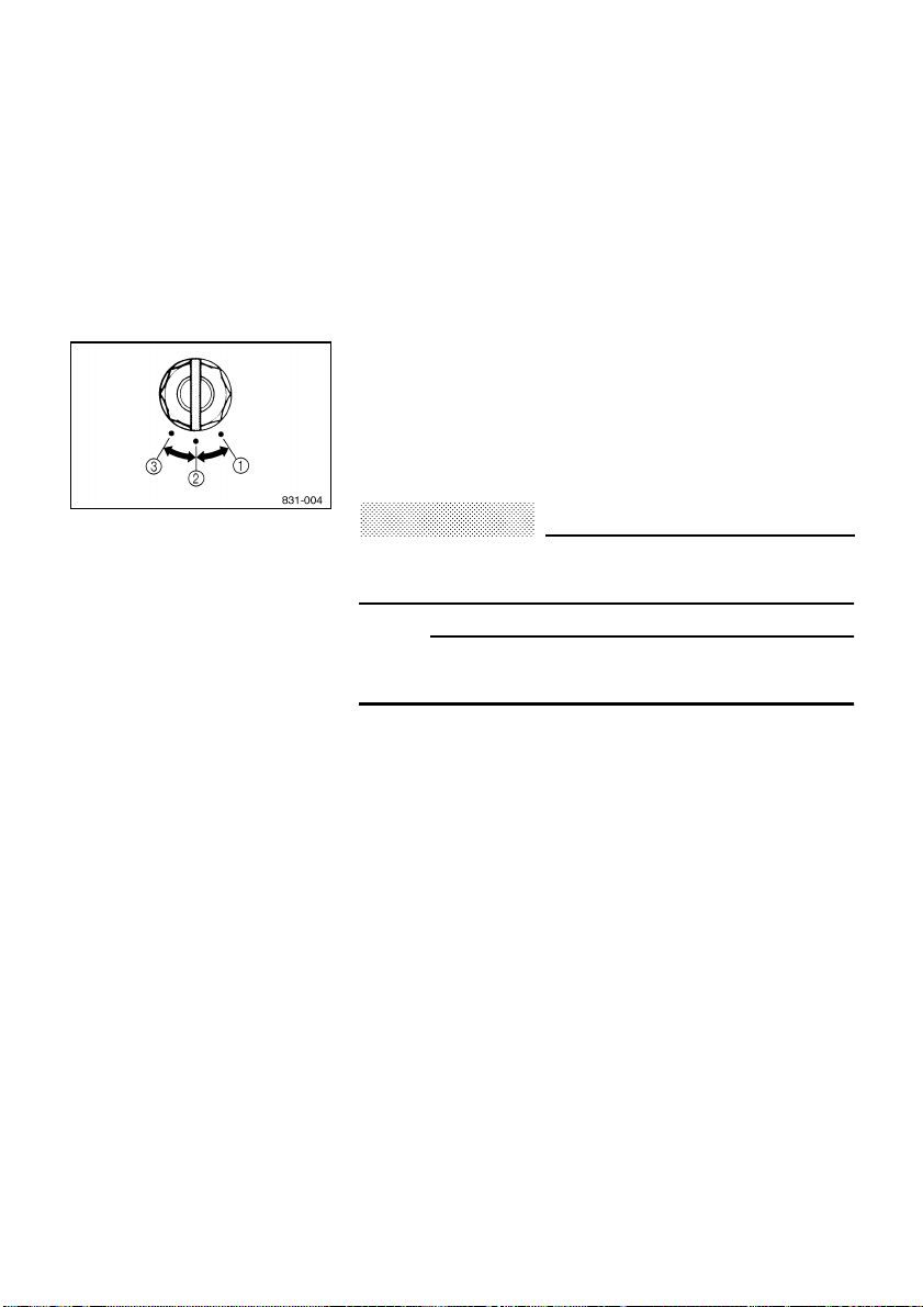
ESU00362
Main switch
The main switch controls the following items.
1
“OFF”
The ignition circuit is switched off.
The key can be removed only in this position.
2
“ON”
The ignition circuit is switched on.
3
“START”
The starting circuit is switched on.
The starter motor starts.
CAUTION
:
@
Release the switch immediately after the engine
starts.
@
NOTE:
@
The headlights, meter lights, and taillights come on after
the engine starts.
@
5-2
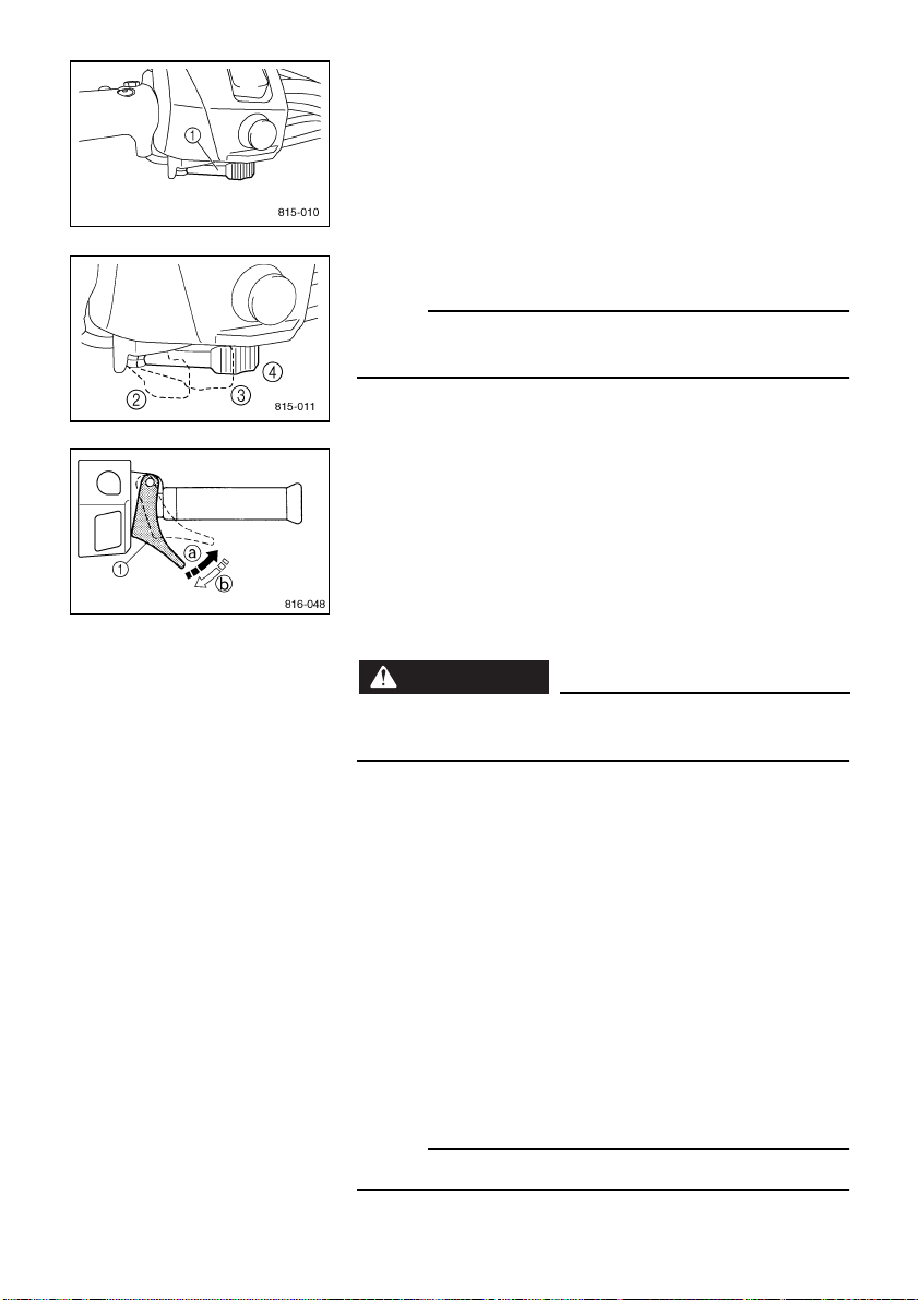
ESU00201
Starter lever (choke)
Use the starter lever (choke) when starting and warming
up a cold engine.
1
Starter lever (choke)
2
When starting a cold engine.
3
Warming up
4
When the engine is warm.
NOTE:
@
Refer the “Starting the engine” section for proper opera-
tion.
@
ESU00022
Throttle lever
Once the engine is running cleanly, squeezing
a
the throt-
tle lever
1
will increase the engine speed and cause
engagement of the drive system. Regulate the speed of
the snowmobile by varying the throttle position. Because
the throttle is spring-loaded, the snowmobile will deceler-
ate, and the engine will return to idle when it is released
b
.
WARNING
@
Check the throttle, brake, and steering for proper
operation before starting the engine.
@
ESU00361
Engine overheating prevention system
This model is equipped with an engine overheating pre-
vention system to prevent overheating when the engine
is idling.
When the engine has been idling for at least 3 minutes
and the coolant temperature has risen above 100 °C
(212 °F), the engine automatically shuts off to prevent
overheating.
NOTE:
The engine can be started after it shuts off.
5-3
ESU00231
Throttle override system (T.O.R.S.)
If the carburetor or throttle cable should malfunction dur-
ing operation, the T.O.R.S. will operate when the throttle
lever is released.
The T.O.R.S. is designed to interrupt the ignition and
keep the engine speed between 2,800 and 3,000 r/min if
the carburetor fails to return to idle when the lever is
released.
WARNING
@
●
If the T.O.R.S. is activated, make sure that the
cause of the malfunction has been corrected and
that the engine can be operated without a prob-
lem before restarting the engine.
●
Be sure to use the specified spark plug and spark
plug cap. Otherwise, the T.O.R.S. will not work
properly.
@
CA-01E
È
Idling/starting
É
Running
Ê
Tr o u b l e
1
Carburetor switch
2
Throttle switch
3
Throttle cable
4
Throttle valve
a
On
b
Off
A
B
C
Mode
Item
Idling/
starting
Running Trouble
Throttle switch Off On Off
Carburetor switch On Off Off
Engine Run Run
T.O.R.S.
will operate
A
B C
5-4
ESU03901
Speedometer unit
The speedometer unit is equipped with the following:
●
a digital speedometer (which shows riding speed)
●
an odometer (which shows the total distance trav-
eled)
●
a tripmeter (which shows the distance traveled since
it was last set to zero)
●
warning indicators (which show self-diagnosis, cool-
ant temperature, fuel level, and oil level warnings)
●
a fuel meter (which shows the fuel remaining in the
fuel tank)
●
a grip/thumb warmer level indicator (which shows the
grip warmer level or the thumb warmer level)
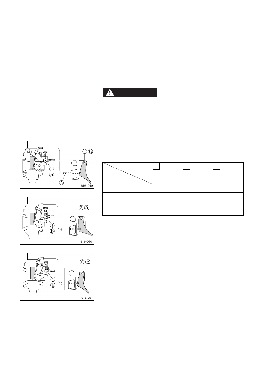
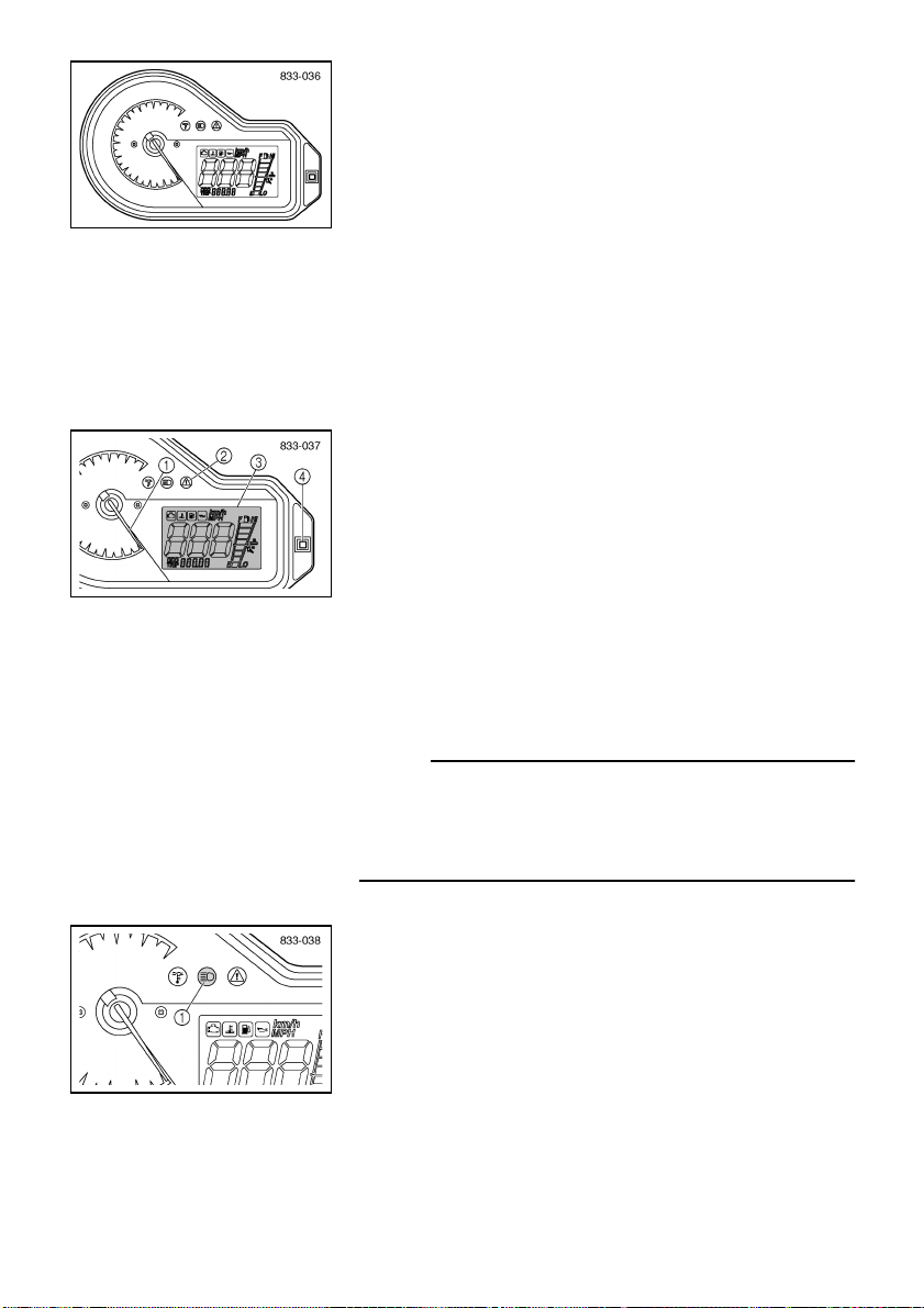
After the engine is started, the tachometer
1
makes one
sweep, and the warning light
2
and all segments of the
meter
3
turn on and off once.
The grip warmer level is initially displayed for 5 seconds,
then switches to the fuel meter display.
Odometer and tripmeter modes
Pushing the select/reset button
4
switches the display
between the odometer mode “ODO” and the tripmeter
mode “TRIP”.
To reset the tripmeter, push the select/reset button for at
least one second while the tripmeter is displayed.
NOTE:
@
To switch the speedometer, odometer, and tripmeter dis-
plays between kilometers and miles, select the odometer
mode “ODO”, and then push the select/reset button
4
for at least 10 seconds while the snowmobile is stopped.
@
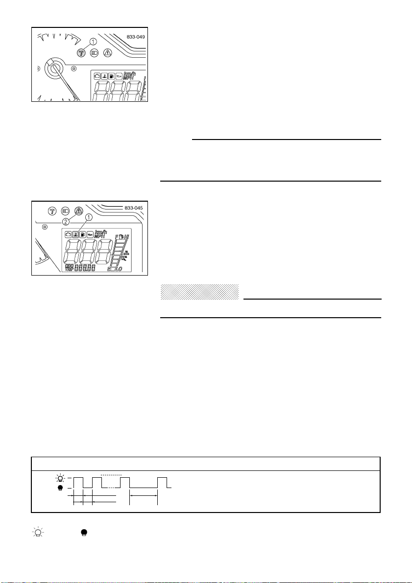
ESU00363
High beam indicator light
The high beam indicator light
1
comes on when the high
beams of the headlights are switched on. (See page 5-12
for headlight beam switch operation.)

5-5
ESU03821
Fuel meter and grip/thumb warmer level indicator
The fuel meter and grip/thumb warmer level indicator
have eight segments
1
which show the amount of fuel
remaining in the fuel tank, the grip warmer level, or the
thumb warmer level.
Fuel meter
As the fuel level decreases in the fuel tank, the segments
disappear until the level goes down to the last segment
“E” (Empty). When this occurs, the fuel level warning
indicator
2
and the warning light
3
come on.
If the fuel level warning indicator and the warning light
come on, fill the fuel tank at the first opportunity.
NOTE:
@
The snowmobile must be stopped on a level surface to
obtain an accurate fuel meter reading. The fuel meter
reading changes as the snowmobile moves and depend-
ing on the inclination of the snowmobile.
@
Grip/thumb warmer level indicator
The grip warmer adjustment switch
1
and the thumb
warmer adjustment switch
2
control the electrically
heated handlebar grips and throttle lever respectively.
To raise the temperature, press each switch to “HI”. To
lower the temperature, press each switch to “LO”.
NOTE:
@
●
The grip warmer indicator
3
comes on and the display
switches to the grip warmer level when the grip warmer
adjustment switch is pressed.
●
The thumb warmer indicator
4
comes on and the dis-
play switches to the thumb warmer level when the
thumb warmer adjustment switch is pressed.
●
The grip/thumb warmer level is displayed for 5 seconds
after releasing the grip/thumb warmer adjustment
switch, then switches to the fuel meter.
●
The top segment of the grip/thumb warmer level indica-
tor flashes once if the grip/thumb warmer adjustment
switch is continually pressed at the maximum level. The
bottom segment of the grip/thumb warmer level indica-
tor flashes once if the grip/thumb warmer adjustment
switch is continually pressed at the minimum level.
●
When the engine is started, the grip/thumb warmer lev-
els are set to the levels saved when the engine was
stopped.
@

5-6
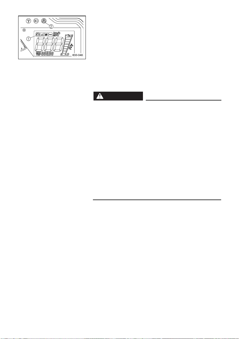
ESU00287
Fuel level warning indicator
The fuel level warning indicator indicates a malfunction-
ing sensor, disconnected coupler, broken lead, or short
circuit when detected by the self-diagnosis device of the
snowmobile.
The fuel level warning indicator
1
, warning light
2
, and
all segments of the fuel meter
3
warn the rider of the
above problems by flashing continuously. (See the table
below for warning indicator, warning light and fuel meter
segment flash pattern.)
When this occurs, have a Yamaha dealer inspect the
snowmobile as soon as possible.
CA-08E
ESU00377
Oil level warning indicator
The oil level warning indicator
1
and the warning light
2
come on when the engine oil level is low.
If the oil level warning indicator and the warning light
come on, place the snowmobile on a level surface and
allow it to idle for one minute.
If the oil level warning indicator and the warning light go
off, the engine oil level is sufficient, however it is getting
low. Add engine oil as soon as possible.
If the oil level warning indicator and the warning light do
not go off, check the engine oil level in the oil tank (see
page 6-3), and add engine oil if necessary.
Warning indicator, warning light, and fuel meter segments of the fuel meter flash pattern
Warning indicator, warning light, and fuel meter
segment flash continuously in this pattern.
: On : Off s: Second
0.5 s 3 s
12 8
0.5 s
· · ·
5-7
ESU03602
Low coolant temperature indicator light
The low coolant temperature indicator light
1
flashes
when the coolant temperature is low and informs the
rider that the snowmobile must be warmed up. After the
engine is started, warm it up until the indicator light goes
off.
The snowmobile can be operated normally after the indi-
cator light goes off.
NOTE:
@
When the low coolant temperature indicator light flashes,
the engine control system prevents the engine speed
from rising even if the throttle lever is pressed.
@
ESU02891
Coolant temperature warning indicator
If the engine overheats, the coolant temperature warning
indicator
1
and the warning light
2
come on. When this
occurs, stop the engine immediately and allow the
engine to cool down, and then check the coolant level in
the coolant reservoir. (See page 6-4.)
CAUTION
:
@
Do not operate the engine if it overheats.
@
The coolant temperature warning indicator indicates a
malfunctioning sensor, disconnected coupler, broken
lead, or short circuit when detected by the self-diagnosis
device of the snowmobile.
The coolant temperature warning indicator and warning
light warn the rider of the above problems by flashing
continuously. (See the table below for warning indicator
and warning light flash pattern.)
When this occurs, have a Yamaha dealer inspect the
snowmobile as soon as possible.
CA-09E
Warning indicator and warning light flash pattern
Warning indicator and warning light flash
continuously in this pattern.
: On : Off s: Second
0.5 s 3 s
12 8
0.5 s
· · ·
5-8
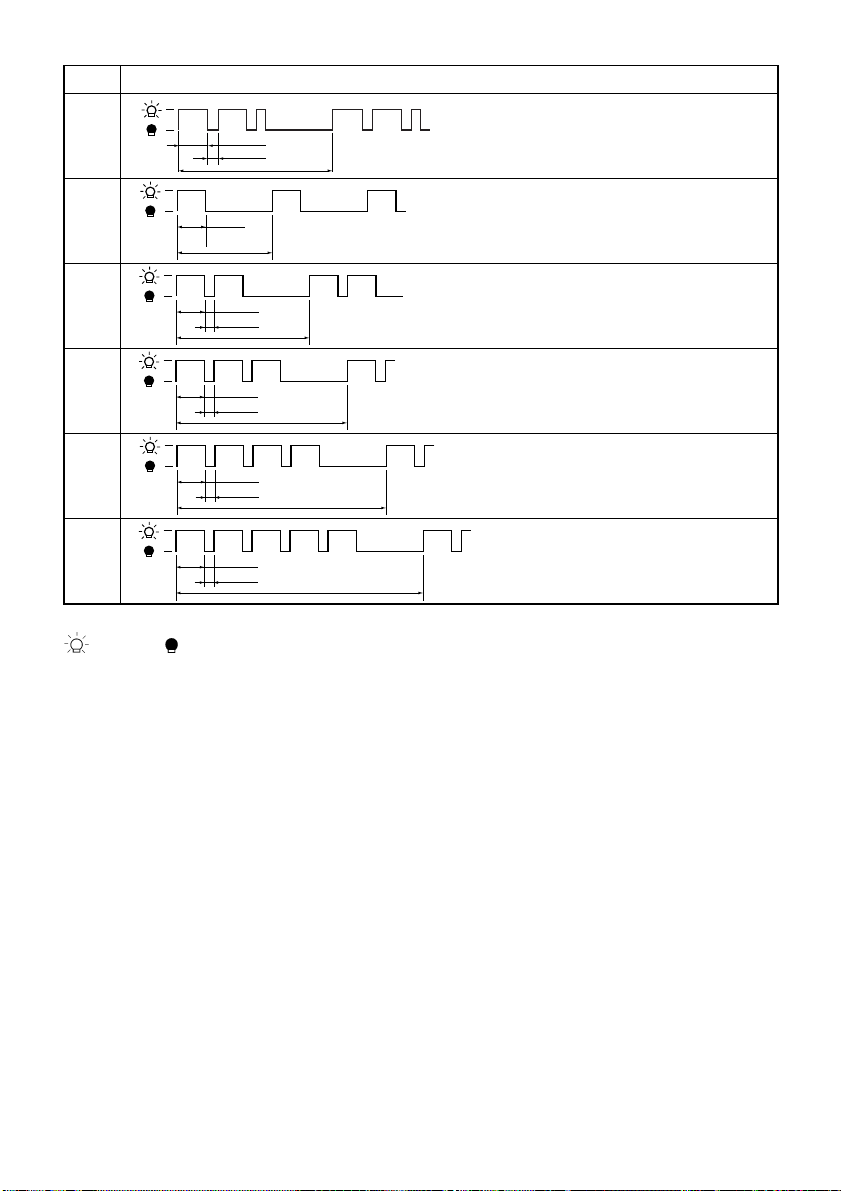
ESU00365
Self-diagnosis warning indicator
The self-diagnosis warning indicator indicates a malfunc-
tioning sensor, disconnected coupler, broken lead, etc.,
when detected by the self-diagnosis device of the snow-
mobile.
The self-diagnosis warning indicator
1
and warning light
2
warn the rider of the above problems by flashing con-
tinuously. If necessary, ask a Yamaha dealer for further
details. (See page 5-9 for warning indicator and warning
light flash patterns.)
WARNING
@
●
If the self-diagnosis warning indicator and warn-
ing light flash continuously during operation,
there may be some problem with the electrical
circuit, lead couplers, etc. (See page 5-9 for warn-
ing indicator and warning light flash pattern num-
bers 1–6.)
●
Stop the engine and allow it to cool off. Then,
check that the wire harness couplers are con-
nected properly in the engine compartment.
●
If the self-diagnosis warning indicator and warn-
ing light flash after the engine has been started,
note the flash pattern, and then have a Yamaha
dealer inspect the snowmobile as soon as possi-
ble.
@
5-9
CA-14E
No. Self-diagnosis warning indicator and warning light flash patterns
1
Warning indicator and warning
light flash continuously in this
pattern.
2
Warning indicator and warning
light flash continuously in this
pattern.
3
Warning indicator and warning
light flash continuously in this
pattern.
4
Warning indicator and warning
light flash continuously in this
pattern.
5
Warning indicator and warning
light flash continuously in this
pattern.
6
Warning indicator and warning
light flash continuously in this
pattern.
: On : Off s: Second
0.75 s
0.25 s
4 s
· · ·
0.75 s
· · ·
2.5 s
0.75 s
0.25 s
· · ·
3.5 s
0.75 s
0.25 s
· · ·
4.5 s
0.75 s
0.25 s
· · ·
5.5 s
0.75 s
0.25 s
· · ·
6.5 s
5-10
ESU00031
Engine stop switch
The engine stop switch
1
is used to stop the engine in
an emergency. Simply push
2
the stop switch to stop the
engine. To start the engine, pull
3
the stop switch and
proceed with starting the engine. (See page 7-1 for more
details.)
During the first few rides, practice using the stop switch
so that you can react quickly in an emergency.
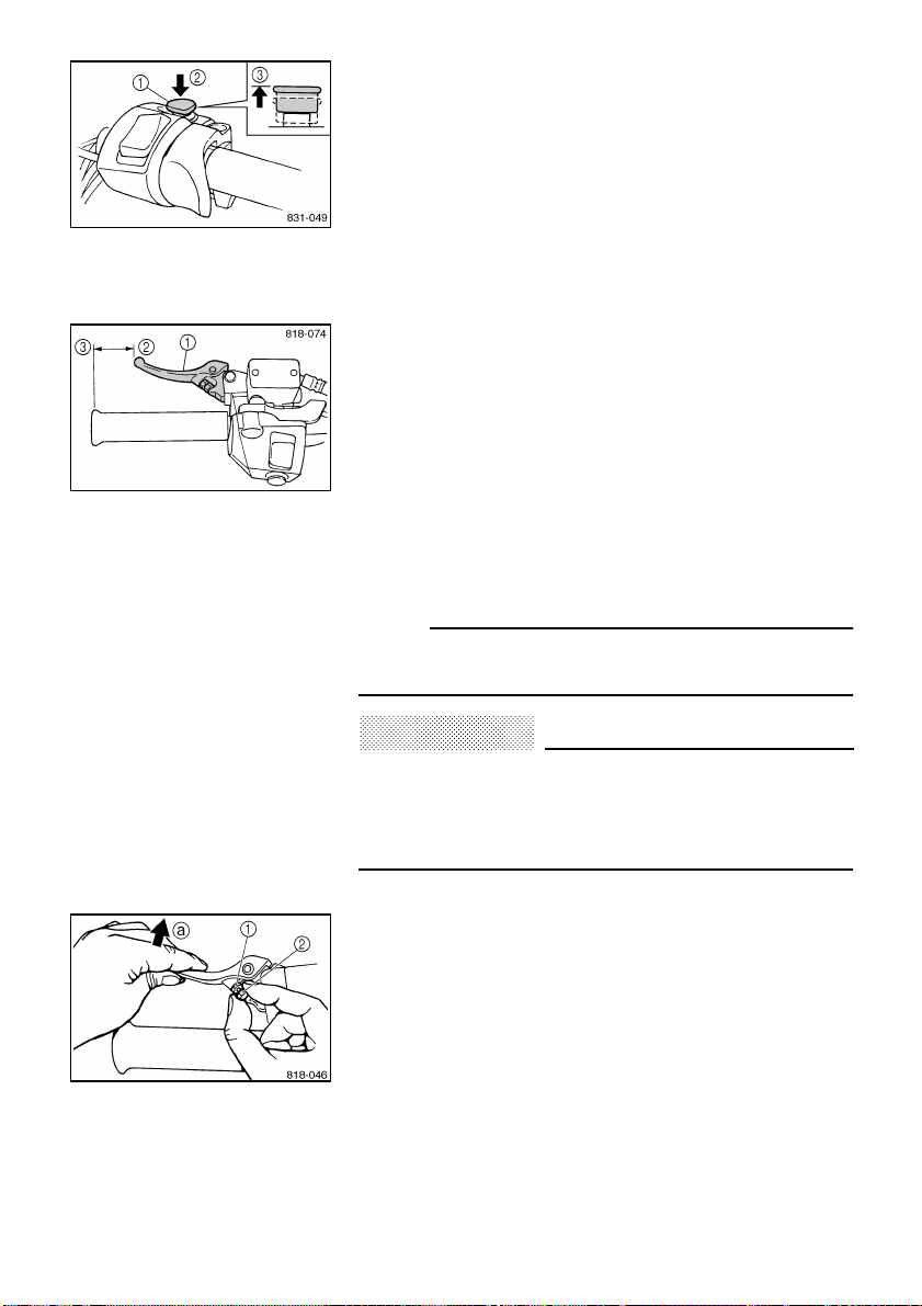
ESU00033
Brake lever
The snowmobile is stopped by braking the entire drive
system.
Squeeze the brake lever towards the handlebar grip to
stop the snowmobile.
1
Brake lever
2
Brake lever end
3
Handlebar end
NOTE:
@
When the brake lever is operated, the brake light will illu-
minate.
@
CAUTION
:
@
Make sure that the brake lever end does not project
out over the handlebar end. This will help prevent
brake lever damage when the snowmobile is placed
on its side for service.
@
The brake lever is equipped with a position adjuster.
To adjust the brake lever position:
1. Loosen the locknut
1
.
2. While lightly pushing the brake lever in direction
a
,
finger tighten the adjusting bolt
2
to set the brake
lever to the desired position.
3. Tighten the locknut securely after adjusting the brake
lever.
5-11
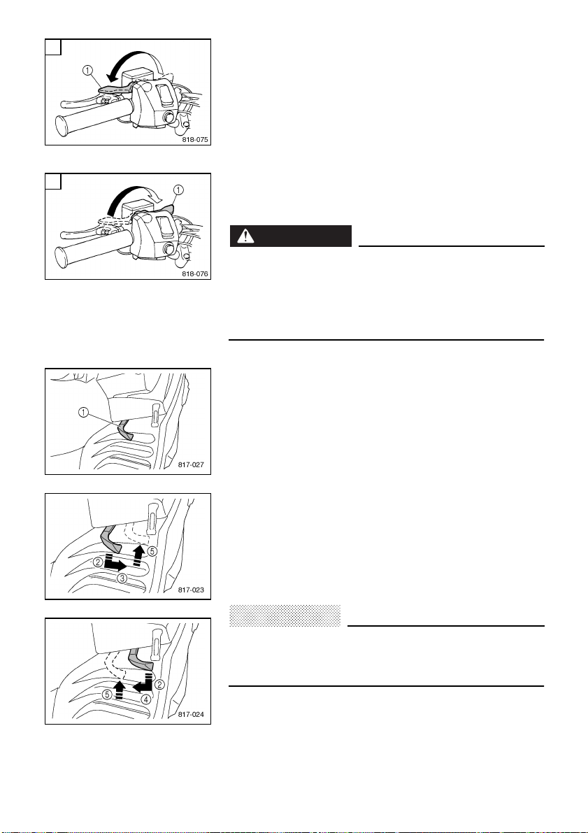
ESU00035
Parking brake lever
When parking the snowmobile or starting the engine,
apply the parking brake by moving the brake lever
1
to
the left.
To release the parking brake, move the parking brake
lever
1
to the right.
È
To apply the parking brake
É
To release the parking brake
WARNING
@
●
Always set the parking brake before attempting to
start the engine.
●
Never run the snowmobile with the parking brake
applied. This may overheat the brake disc and
reduce braking ability.
@
ESU00341
Shift lever
For RX10R/RX10RS/RXW10/RXW10S
The shift lever is used to put the snowmobile into forward
or reverse. After coming to a complete stop, pull the shift
lever out, slide it to “FWD” or to “REV” until it stops, and
then release it.
1
Shift lever
2
Pull out
3
Slide to “FWD” (Forward)
4
Slide to “REV” (Reverse)
5
Release
CAUTION
:
@
Do not shift from “FWD” to “REV” or from “REV” to
“FWD” while the snowmobile is moving. Otherwise,
the drive system could be damaged.
@
A
B
Loading...