


 Loading...
YAMAHA F40BMHD, F40BWHD, F40BED, F40BET, F40MH PARTS CATALOGUE
...ESERVICE MANUAL
FMANUEL D’ENTRETIEN
D WARTUNGSHANDBUCH ES MANUAL DE SERVICIO
290372
WORLDWIDE
F40BMHD, F40BWHD, F40BED, F40BET
USA, CANADA
F40MH, F40ER, F40TR
67C-28197-Z9-C1

E
PREFACE
This manual has been prepared by the Yamaha Motor Company, Ltd. primarily for use by Yamaha dealers and their trained mechanics when performing maintenance procedures and repairs to Yamaha equipment. It has been written to suit the needs of persons who have a basic understanding of the mechanical and electrical concepts and procedures inherent in the work, for without such knowledge attempted repairs or service to the equipment could render it unsafe or unfit for use.
Because the Yamaha Motor Company, Ltd. has a policy of continuously improving its products, models may differ in detail from the descriptions and illustrations given in this publication. Use only the latest edition of this manual. Authorized Yamaha dealers are notified periodically of modifications and significant changes in specifications and procedures, and these are incorporated in successive editions of this manual.
F40B
SERVICE MANUAL
©1999 Yamaha Motor Co., Ltd. 1st Edition, September 1999 All rights reserved.
No part of this publication may be reproduced or transmitted in any form or by any means including photocopying and recording without the written permission of the copyright holder. Such written permission must also be obtained before any part of this publication is stored in a retrieval system of any nature.
Printed in Japan

F |
D |
ES |
|
|
|
PREFACE
Ce manuel a été préparé par la Yamaha Motor Company principalement à l’intention des concessionnaires Yamaha
et de leurs mécaniciens qualifiés afin de les assister lors de l’entretien et la réparation des produits Yamaha. Ce manuel est destiné à des personnes possédant les connaissances de base en mécanique et en électricité sans lesquelles l’exécution de réparations ou d’entretiens peut rendre les machines impropres ou dangereuses à l’emploi.
La Yamaha Motor Company, Ltd. s’efforce en permanence d’améliorer ses produits. Par conséquent, il se peut que les modèles diffèrent légèrement des descriptions et illustrations de ce manuel. Les modifications et les changements significatifs dans les caractéristiques ou les procédés sont notifiés à tous les concessionnaires Yamaha et sont publiés dans les éditions ultérieures de ce manuel.
F40B
MANUEL D’ENTRETIEN
©1999 Yamaha Motor Co., Ltd.
1ère édition, Septembre 1999
Tous droits réservés.
Toute reproduction ou transmission de ce manuel, même partielle, par quelque procédé que ce soit, y compris par photocopie ou enregistrement, requiert l’accord écrit préalable de la
Yamaha Motor Co., Ltd.
De même, l’introduction de toute partie de ce manuel dans un système d’archivage requiert cet accord écrit préalable.
Imprimé au Japon
VORWORT
Dieses Handbuch wurde von der Yamaha Motor Company, Ltd. vorrangig für Yahama-Vertragshän- dler und deren qualifizierte Mechaniker geschrieben, um sie bei der Durchführung von Wartungs und Reparaturarbeiten an Yamaha-Motoren zu unterstützen. Es werden Grundkenntnisse der mechanischen und elektrischen Wirkungsweise und der Arbeitsverfahren vorausgesetzt, denn ohne diese Grundkenntnisse versuchte Wartungs und Reparaturarbeiten machen das Produkt eher unsicher oder sogar gebrauchsunfähig.
Die Yamaha Motor Company, Ltd. ist stets bestrebt, ihre Produkte ständig zu verbessern. Einzelne Modelle können im Detail von den hier enthaltenen Beschreibungen und Abbildungen abweichen. Benutzen Sie immer nur die neueste Ausgabe dieses Handbuchs. Autorisierte Yamaha-Ver- tragshändler werden regelmäßig vorab über Modifikationen und wesentliche Änderungen der technischen Daten und Verfahren unterrichtet, die in der jeweils nächsten Ausgaben dieses Handbuchs eingearbeitet werden.
F40B
WARTUNGSHANDBUCH
©1999 Yamaha Motor Co., Ltd.
1. Ausgabe, September 1999
Alle Rechte vorbehalten.
Diese Veröffentlichung darf auch teilweise in keiner Weise oder durch irgendein Verfahren ohne die schriftlichts Genehmigung des Urheberrechts-Inhabers reproduziert oder übertragen werden. Dies gilt auch für Fotokopien und Aufzeichnungen. Die schriftliche Genehmigung ist vor der Übernahme in irgendein Informationssystem einzuholen.
Gedruckt in Japan
PREFACIO
Este manual ha sido preparado por Yamaha Motor Company Ltd. principalmente para que lo empleen los concesionarios Yamaha y sus mecánicos cualificados al llevar a cabo los procedimientos de mantenimiento y de reparación de los equipos Yamaha. Se ha escrito para adaptarlo a las necesidades de las personas que ya tienen un conocimiento básicos de los conceptos mecánicos y eléctricos y de los procedimientos inherentes al trabajo, porque sin tales conocimientos las reparaciones o el servicio del equipo podría dejar el equipo inseguro o inadecuado para la utilización.
Puesto que Yamaha Motor Company, Ltd. sigue una política de mejora continua de sus productos, los modelos pueden diferir en detalles de las descripciones e ilustraciones dadas en esta publicación. Emplee sólo la última edición de este manual. Se notifica periódicamente a los concesionarios autorizados Yamaha sobre las modificaciones y cambios importantes en las especificaciones y procedimientos, y tales cambios se incorporan en las ediciones subsiguientes de este manual.
F40B
MANUAL DE SERVICIO
©1999 Yamaha Motor Co., Ltd.
1ª Edición, SEPTIEMBRE 1999
Reservados todos los derechos.
Queda prohibida la reproducción o transmisión de esta publicación, ya sea en su totalidad o en parte, y por cualquier medio, incluido su fotocopiado o grabación, sin el consentimiento por escrito del titular del derecho de copyright.
También deberá obtenerse este consentimiento antes de proceder al
almacenamiento de cualquier parte de esta publicación en un sistema de búsqueda documental de cualquier naturaleza.
Impreso en Japón

E
HOW TO USE THIS MANUAL
MANUAL FORMAT
All of the procedures in this manual are organised in a sequential, step-by-step format. The information has been compiled to provide the mechanic with an easy to read, handy reference that contains comprehensive explanations of all disassembly, repair, assembly, and inspection operations.
In this revised format, the condition of a faulty component will precede an arrow symbol and the course of action required will follow the symbol, e.g.,
•Bearings
Pitting/scratches → Replace.
To assist you in finding your way through this manual, the section title and major heading is given at the top of every page.
MODEL INDICATION
Multiple models are referred to in this manual and their model indications are noted as follows.
Model name |
F40BMHD |
F40BWHD |
F40BED |
F40BET |
|
|
|
|
|
USA and Canada name |
F40MH |
— |
F40ER |
F40TR |
|
|
|
|
|
Indication |
F40BMHD |
F40BWHD |
F40BED |
F40BET |
|
|
|
|
|
ILLUSTRATIONS
The illustrations within this service manual represent all of the designated models.
CROSS REFERENCES
The cross references have been kept to a minimum. Cross references will direct you to the appropriate section or chapter.

F
STRUCTURE DU MANUEL
FORMAT DU MANUEL
Tous les procédés repris dans ce manuel sont décrits pas à pas. Les informations ont été condensées pour fournir au mécanicienun guide pratique et facile à lire, contenant des explications claires pour tous les procédés de démontage, de réparation, de remontage et de vérification.
L’état d’une pièce défectueuse est mentionné et est suivi d’une flèche et de la mesure à prendre pour chaque symptôme décelé.insi,A par exemple:
•Roulements
Piqûres/endommagements → Remplacer.
Pour plus de facilité, le nom du chapitre et les titres principaux figurent à l’en-tête de chaque page.
INDICATION DE MODELE
Ce manuel est destiné à plusieurs modèles. La liste de ces modèles est reprise ci-dessous.
Nom de modèle |
F40BMHD |
F40BWHD |
F40BED |
F40BET |
|
|
|
|
|
Nom pour les E.-U. et |
F40MH |
— |
F40ER |
F40TR |
le Canada |
|
|
|
|
|
|
|
|
|
|
|
|
|
|
Indication |
F40BMHD |
F40BWHD |
F40BED |
F40BET |
|
|
|
|
|
ILLUSTRATIONS
Les illustrations représentent les modèles désignés.
RENVOIS
Les renvois ont été évités au maximum. Les renvois réfèrent à la section ou au chapitre appropriés.

D
BENUTZUNG DIESES HANDBUCHS
AUFBAU
Alle in diesem Handbuch enthaltenen Verfahren sind in der richtigen Reihenfolge Schritt für Schritt beschrieben. Die Informationen wurden so aufbereitet, daß dem Mechaniker in leicht verständlicher, handlicher Form alle notwendigen Handgriffe beim Zerlegen, bei der Reparatur und dem Zusammenbau sowie bei der Inspektion ausführlich erklärt werden.
Bei dieser neuen Darstellungsweise folgt nach der Zustandsbeschreibung eines schadhaften Teils ein Pfeil, der auf die notwendige Aktion hinweist, z.B:
•Lager
Lochfraß/Kratzer → Ersetzen.
Die Abschnittstitel finden sich zur Bezugnahme in der Kopfzeile wieder.
MODELLANGABE
Dieses Handbuch bezieht sich auf mehrere Modelle. Die verschiedenen Modelle sind wie folgt gekennzeichnet.
Modellbezeich- |
F40BMHD |
F40BWHD |
F40BED |
F40BET |
nung |
|
|
|
|
|
|
|
|
|
Bezeichnug für USA |
F40MH |
— |
F40ER |
F40TR |
und Kanada |
|
|
|
|
|
|
|
|
|
|
|
|
|
|
Bezeichnung |
F40BMHD |
F40BWHD |
F40BED |
F40BET |
|
|
|
|
|
ABBILDUNGEN
Die Abbildungen in diesem Wartungshandbuch gelten für alle angegebenen Modelle.
QUERVERWEISE
Querverweise wurden auf ein Minimum beschränkt. Querverweise führen Sie zum entsprechenden Abschnitt oder Kapitel.

ES
CÓMO EMPLEAR ESTE MANUAL
FORMATO DEL MANUAL
Todos los procedimientos de este manual están organizados en un formato de paso a paso secuencial. La información ha sido compilada para proporcionar al mecánico una referencia útil y de fácil lectura que contiene detalladas explicaciones de todas lasoperaciones de desmontaje, reparación, montaje e inspección.
En este formato revisado, el estado de un componente averiado irá seguido de un símbolo de flecha y de la acción requerida detrás de la fecha, por ejemplo:
•Cojinetes
Picadas/rayadas → Reemplazar.
Para ayudarle a encontrar lo que busca en este manual, el título de la sección y el encabezamiento principal se incluye al prin cipio de cada página.
INDICACIÓN DEL MODELO
Este manual hace referencia a múltiples modelos, y sus indicaciones de modelo se indican de la forma siguiente.
Nombre del modelo |
F40BMHD |
F40BWHD |
F40BED |
F40BET |
|
|
|
|
|
Nombre de EE.UU. y |
F40MH |
— |
F40ER |
F40TR |
CANADÁ |
|
|
|
|
|
|
|
|
|
|
|
|
|
|
Indicación |
F40BMHD |
F40BWHD |
F40BED |
F40BET |
|
|
|
|
|
ILUSTRACIONES
Las ilustraciones de este manual de servicio representan a todos los modelos designados.
REFERENCIAS DE CONSULTA
Las referencias de consulta se han manteniendo al mínimo. Estas referencias indican la sección o capítulo que debe consultarse.
E
IMPORTANT INFORMATION
In this Service Manual particularly important information is distinguished in the following ways.
The safety Alert Symbol means ATTENTION! BECOME ALERT! YOUR SAFETY IS INVOLVED!

 WARNING
Failure to follow WARNING instructions could result in severe injury or death to the machine operator, a bystander or a person inspecting or repairing the outboard motor.
CAUTION:
A CAUTION indicates special precautions that must be taken to avoid damage to the outboard motor.
NOTE:
A NOTE provides key information to make procedures easier or clearer.

F |
D |
ES |
|
|
|
INFORMATIONS IMPORTANTES
Les informations particulièrement importantes sont repérées par les notations suivantes.
 Le symbole d’alerte sécurité signifie ATTENTION! SOYEZ ATTENTIF! VOTRE SECURITE EST MENACEE!
 AVERTISSEMENT
Le non-respect d’une instruction AVERTISSEMENT peut blesser ou entraîner la mort de l’opérateur, d’un passager ou d’une personne inspectant ou réparant le moteur hors-bord.
ATTENTION:
ATTENTION indique les consignes qui doivent être respectées afin d’éviter d’endommager le moteur hors-bord.
N.B.:
N.B. donne des informations importantes qui facilitent et expliquent les différentes opérations.
WICHTIGE INFORMATION
Informationen in diesem Wartungshandbuch, die von besonderer Wichtigkeit sind, werden auf eine der folgenden Arten hervorgehoben.
 Dieses Warnsymbol bedeutet: VORSICHT! ES GEHT UM IHRE SICHERHEIT!

 WARNUNG
Eine WARNUNG enthält Anweisungen, die eingehalten werden müssen, um Verletzungen, möglicherweise sogar mit Todesfolge, für Bediener, in der Nähe befindliche Personen oder Techniker, die Inspektionen oder Reparaturen an Außenbordmotoren vornehmen, zu vermeiden.
ACHTUNG:
Unter ACHTUNG finden Sie spezielle Vorsichtsmaßnahmen, die eingehalten werden müssen, um Beschädigungen am Außenbordmotor zu vermeiden.
HINWEIS:
Ein HINWEIS enthält Informationen, die einen Vorgang einfacher oder deutlicher machen.
INFORMACIÓN IMPORTANTE
En este manual de servicio, la información particularmente importante se distingue según se indica a continuación.
 El símbolo de alerta de seguridad significa ¡ATENCION, ESTA EN JUEGO SU PROPIA SEGURIDAD!

 ATENCION
El incumplimiento de este tipo de instrucciones de ATENCION puede causar graves lesiones, e incluso la muerte, al operador del motor, a las personas a su alrededor o al técnico que inspeccione o repare el motor fuera de borda.
PRECAUCION:
Una instrucción de PRECAUCION indica precauciones especiales que debe observar para evitar dañar el motor fuera de borda.
NOTA:
La NOTA proporciona información clave que facilita o clarifica determinados procedimientos.
E
HOW TO USE THIS MANUAL
1  The main points regarding removing/installing and disassembling/assembling procedures are shown in the exploded views.
2  The numbers in the exploded views indicate the required sequence of the procedure and should be observed accordingly.
3  Symbols are used in the exploded views to indicate important aspects of the procedure. A list of meanings for these symbols is provided on the following page.
4  It is important to refer to the job instruction charts at the same time as the exploded views. These charts list the sequence that the procedures should be carried out in, as well as providing explanations on part names, quantities, dimensions and important points relating to each relevant task.
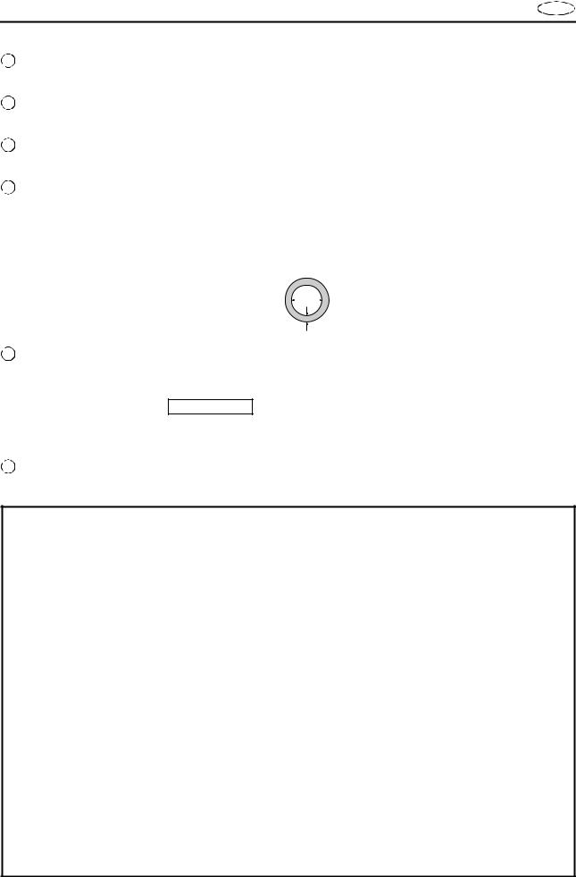
Example: |
39.5 × 2.5 mm: inside diameter (D) × ring diameter (d) |
||||
O-ring size |
|||||
|
|
|
D |
|
|
|
|
|
|||
d
5  In addition to tightening torques, the dimensions of the bolts and screws are also mentioned.
Example: |
10 × 25 mm : bolt and screw diameter (D) × lenght (L) |
Bolt and screw size |
6  In addition to the exploded views and job instruction charts, this manual provides individual illustrations when further explanations are required to explain the relevant procedure.
F |
D |
ES |
|
|
|
STRUCTURE DU MANUEL |
BENUTZUNG DIESES HANDBUCHS |
aLes principaux points concernant les procédures de dépose/installation et de démontage/remontage sont illustrés sur les vues en éclaté.
bLes numéros sur les vues en éclaté indiquent l’ordre nécessaire de la procédure et doivent être respectés en conséquence.
cDes symboles sont utilisés sur les vues en éclaté pour indiquer les aspects importants de la procédure.
Une liste de légendes de ces symboles figure sur la page suivante.
dIl est important de se reporter aux tableaux d’instructions en même temps qu’aux vues en éclaté. Ces tableaux énumèrent l’ordre dans lequel les procédures doivent être réalisées et apportent également des explications sur le nom des pièces, les quantités, les dimensions et des points importants concernant chaque tâche correspondante.
Exemple:
Taille du joint torique 39,5 × 2,5
mm:diamètre intérieur (D) × diamètre annulaire (d)
eEn plus des couples de serrage, les dimensions des boulons et des vis sont également mentionnées.
Exemple:
Taille de boulon et de vis
10 × 25 mm : diamètre de boulon et de vis (D) × longueur (L)
fEn plus des vues en éclaté et des tableaux d’instructions des tâches, ce manuel présente des illustrations individuelles lorsque d’autres précisions sont nécessaires pour expliquer la procédure correspondante.
aDie Hauptpunkte in Bezug auf Verfahren für Ausbau/Einbau und Demontage/Montage werden in den Explosionszeichnungen aufgezeigt.
bDie Nummern in den Explosionszeichnungen zeigen den erforderlichen Ablauf des Verfahrens an. Dieser sollte entsprechend befolgt werden.
cIn den Explosionszeichnungen werden Symbole verwendet, um wichtige Aspekte der Verfahren aufzuzeigen.
Eine Liste der Bedeutungen dieser Symbole folgt auf der nächsten Seite.
dEs ist wichtig auf die Arbeitsanweisungstabelle sowie auf die Explosionszeichnungen Bezug zu nehmen. Diese Tabellen führen den Ablauf der Verfahren auf, die durchgeführt werden sollten. Ebenso sind Erklärungen bezüglich Teilbezeichnungen, Mengen, Abmessungen und wichtige Punkte über jeden Arbeitsvorgang angegeben.
Beispiel:
O-Ring Größe 39,5 × 2,5 mm: Innendurchmesser (D) × Ring-
durchmesser (d)
eZusätzlich zu den Anzugsdrehmomenten sind die Abmessungen der Bolzen und Schrauben
ebenfalls aufgeführt. Beispiel: Schraubengröße
10 × 25 mm : Schraubendurchmesser (D) × Länge (L)
fZusätzlich zu den Explosionszeichnungen und Arbeitsanweisungstabellen gibt dieses Handbuch einzelne Darstellungen, falls weitere Erklärungen notwendig sind, um das entsprechende Verfahren zu erklären.
CÓMO EMPLEAR ESTE MANUAL
a Los pasos principales que debe tener en cuenta en el procedimiento de extracción/instalación y de desmontaje/montaje de las piezas aparece en ilustraciones detalladas.
bLos números que aparecen en las ilustraciones detalladas indican la secuencia necesaria del procedimiento y debe mantenerse adecuadamente .
cLos símbolos utilizados en las ilustraciones detalladas indican aspectos importantes del procedimiento.
En la página siguiente encontrará una lista del significado de los símbolos.
dEs importante consultar las tablas de instrucciones de los trabajos al mismo tiempo que las ilustraciones detalladas. Estas tablas indican la secuencia en la que debe realizar el procedimiento, además de proporcionar explicaciones correspondientes a la denominación de la pieza, cantidad, dimensiones y aspectos importantes relacionados con cada tarea relevante.
Por ejemplo:
Tamaño de las juntas tóricas 39,5 × 2,5 mm: diámetro interno (D)×
diámetro del aro (d)
eAdemás de la torsión de apriete, se mencionan las dimensiones de los pernos y los tornillos.
Por ejemplo:
Tamaño del perno y el tornillo
10 × 25 mm : diámetro (D)× longitud (L) del perno y el tornillo
fAdemás de las ilustraciones detalladas y las tablas de instrucciones de los trabajos, este manual proporciona ilustraciones individuales cuando se requieran mayores explicaciones sobre el procedimiento relevante.

|
|
|
|
|
E |
1 |
2 |
|
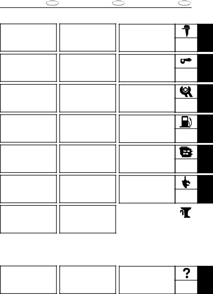
SYMBOLS |
|
|
GEN |
SPEC |
|
Symbols 1 to 9 |
are designed as thumb- |
|
|
tabs to indicate the content of a chapter. |
||||
INFO |
|
||||
|
|
|
|
|
|
3 |
4 |
|
1 |
General information |
|
|
2 |
Specifications |
|
||
CHK |
FUEL |
|
|
||
|
3 |
Periodic check and adjustments |
|||
ADJ |
|
||||
|
|
4 |
Fuel system |
|
|
|
|
|
|
||
5 |
6 |
|
5 |
Power unit |
|
POWR |
LOWR |
|
6 |
Lower unit |
|
|
7 |
Bracket unit |
|
||
|
|
|
8 |
Electrical systems |
|
7 |
8 |
|
9 |
Trouble analysis |
|
BRKT |
ELEC |
– |
+ |
|
|
|
|
|
Symbols 10 to 15 |
indicate specific data. |
|
9 |
|
|
|
|
|
|
10 |
|
|
|
|
|
10 |
Special tool |
|
|
|
|
|
|
|
|
|
|
|||||||
|
TRBL |
|
|
|
|
|
|
|
|
|
|
||||
|
|
|
|
|
|
|
|
|
|
|
11 |
Specified liquid |
|||
|
ANLS |
|
|
|
|
|
|
|
|
|
|
12 |
Specified engine speed |
||
|
|
|
|
|
|
|
|
|
|
|
|
|
|
13 |
Specified torque |
|
|
|
|
|
|
|
|
|
|
|
|
|
|
||
11 |
|
|
|
|
|
|
12 |
|
|
|
|
|
|||
|
|
|
|
|
|
|
|
|
|
|
14 |
Specified measurement |
|||
|
|
|
|
|
|
|
|
|
|
|
|||||
|
|
|
|
|
|
|
|
|
|
|
|
|
|
||
|
|
|
|
|
|
|
|
|
|
|
|
|
|
15 |
Specified electrical value |
|
|
|
|
|
|
|
|
|
|
|
|
|
|
|
[Resistance (Ω), Voltage (V), Electric current |
|
|
|
|
|
|
|
|
|
|
|
|
|
|
|
(A)] |
|
|
|
|
|
|
|
|
|
|
|
|
|
|
|
|
|
|
|
|
|
|
|
|
|
|
|
|
|
|
|
|
13 |
|
|
|
|
|
|
14 |
|
|
|
|
|
Symbol 16 to 18 in an exploded diagram |
||
. |
|
|
|
|
|
|
|
||||||||
|
|
|
|
|
|
|
|
|
|||||||
|
|
|
|
T |
|
|
|
|
|
|
|
|
|
||
|
. |
|
|
|
|
|
|
|
|
|
|
||||
|
|
|
|
|
R |
|
|
|
|
|
|
|
|
|
|
|
|
|
|
|
|
|
|
|
|
|
|
|
|
indicate the grade of lubricant and the loca- |
|
|
|
|
|
|
|
|
|
|
|
|
|
|
|
||
15 |
|
|
|
|
|
|
16 |
|
|
|
|
|
tion of the lubrication point. |
||
|
|
|
|
|
|
|
|
|
|
|
|||||
|
|
|
|
|
|
|
|
|
|
|
|
|
|
16 |
Apply Yamaha 4-stroke motor oil |
|
|
|
|
|
|
|
|
|
|
E |
17 |
Apply water resistant grease |
|||
|
|
|
|
|
|
|
|
|
|||||||
|
|
|
|
|
|
|
|
|
|
|
|
|
|
18 |
(Yamaha grease A, Yamaha marine grease) |
|
|
|
|
|
|
|
|
|
|
|
|
|
|
||
|
|
|
|
|
|
|
|
|
|
|
|
|
|
Apply molybdenum disulfide oil |
|
17 |
|
|
|
|
|
|
18 |
|
|
|
|
|
|||
|
|
|
A |
|
|
M |
|
Symbols 19 to 24 in an exploded dia- |
|||||||
|
|
|
|
|
|
|
|
||||||||
|
|
|
|
|
|||||||||||
|
|
|
|
|
|
|
|
|
|
|
|
|
|
gram indicate the grade of the sealing or |
|
|
|
|
|
|
|
|
|
|
|
|
|
|
|
locking agent and the location of the appli- |
|
19 |
|
|
|
|
|
|
20 |
|
|
|
|
|
cation point. |
||
|
|
|
GM |
4 |
|
19 |
Apply Gasket Maker® |
||||||||
|
|
|
|
20 |
Apply Yamabond #4 |
||||||||||
|
|
|
|
|
|
|
|
|
|
|
|
|
|
||
|
|
|
|
|
|
|
|
|
|
|
|
|
|
|
(Yamaha bond number 4) |
|
|
|
|
|
|
|
|
|
|
|
|
|
|
21 |
Apply LOCTITE® No.271 (Red LOCTITE) |
21 |
|
|
|
|
|
|
22 |
|
|
|
|
|
|||
|
|
|
LT |
|
|
LT |
22 |
Apply LOCTITE® No.242 (Blue LOCTITE) |
|||||||
|
|
|
|
|
23 |
Apply LOCTITE® No.572 |
|||||||||
271 |
|
|
|
242 |
|
||||||||||
|
|
|
|
24 |
Apply silicon sealant |
||||||||||
|
|
|
|
|
|
|
|
|
|
|
|
|
|
||
23 |
|
|
|
|
|
|
24 |
|
|
|
|
|
|
|
|
|
|
|
LT |
|
|
|
|
|
|
|
|
||||
|
|
|
|
|
SSLT |
|
|
|
|
||||||
|
|
|
|
|
|
|
|
|
|
|
|
|
|||
572 |
|
|
|
|
|
|
|
|
|
|
|
||||

F |
D |
ES |
|
|
|
SYMBOLES
Les symboles a à i servent d’onglets et indiquent le contenu des différents chapitres:
aInformations générales
bSpécifications
cVérifier périodique et réglage
dSystème d’alimentation
eMoteur
fBloc de propulsion
gUnité de support
hEquipement électrique
iDépannage
Les symboles j à o apportent certaines précisions:
jOutillage spécial
kLiquide spécifié
lVitesse du moteur spécifiée
mCouple spécifié
nMesure spécifiée
oValeur électrique spécifiée [résistance (Ω), tension (V), courant électrique (A)]
Les symboles p à r dans les vues en éclaté donnent la qualité de lubrifiant à employer et les points de graissage:
pAppliquer de l’huile moteur 4 temps Yamaha.
qAppliquer de la graisse hydrofuge (graisse Yamaha A, graisse Yamaha marine).
rAppliquer de l’huile au bisulphure de molybdène.
Les symboles s à x dans les vues en éclaté indiquent la qualité des liquides d’étanchéité et de l’agent bloquant à employer ainsi que les points d’application:
sAppliquer du Gasket marker® .
tAppliquer du Yamabond n°4
uAppliquer du LOCTITE® n° 271 (LOCTITE rouge)
vAppliquer du LOCTITE® n° 242 (LOCTITE bleu)
wAppliquer du LOCTITE® n° 572
xAppliquer une pâte d’étanchéité au silicone.
SYMBOLE
Die Symbole a bis i sind Randmarkierungen, die aufden Inhalt der einzelnen Kapitel hinweisen.
aAllgemeines
bTechnische Daten
cRegelmäßige kontrollieren und Einstellungen
dKraftstoffanlage
eMotor
fAntriebseinheit
gMotorhalterung
hElektrische Anlage
iStörungssuche
Die Symbole j bis o zeigen spezifische Daten an:
jSpezialwerkzeug
kSpezielle Flüssigkeit
lVorgeschriebene Motordrehzahl
mSchrauben-Anzugsmoment
nSpezielle Messung
oElektrischer Meßwert [Widerstand (Ω), Spannung (V), Stromstärke (A)]
Die Symbole p bis r zeigen in einer Explosionszeichnung den Schmiermitteltyp und die Schmierstelle an:
pYamaha-Viertakt-Motoröl auftragen.
qWasserfestes Fett auftragen (Yamaha-Fett A, Yamaha-Boots- fett)
rMolybdänsulfid-Öl auftragen
Die Symbole s bis x zeigen in einer Explosionszeichnung den Typ des Dichtungsmittels oder Klebers und die Anwendungsstelle an.
sGasket maker® auftragen
tYamabond #4 auftragen (Yamaha Klebstoff Nr. 4)
uLOCTITE® Nr. 271 (rotes LOCTITE) auftragen
vLOCTITE® Nr. 242 (blaues LOCTITE) auftragen
wLOCTITE® Nr. 572 auftragen
xSilikon-Dichtungsmasse auftragen
SÍMBOLOS
Los símbolos a a i identifican el contenidos de un capítulo.
aInformación general
bEspecificaciones
cCompruebe periódica y ajuste
dSistema de combustible
eMotor
fUnidad inferior
gUnidad de ménsula
hSistemas eléctricos
iAnálisis de averías
Los símbolos j a o indican datos específicos:
jHerramienta especial
kLíquido especificado
lVelocidad del motor especificada
mTorsión especificada
nMedición especificada
oValor eléctrico especificado [Resistencia (Ω), Tensión (V), Corriente eléctrica (A)]
Los símbolos p a r de un diagrama detallado indican el grado de lubricante y la situación del punto de lubricación:
pAplique aceite de motor de 4 tiempos Yamaha.
qAplicar grasa hidrófuga Yamaha (grasa náutica A Yamaha, grasa náutica Yamaha)
rAplicar aceite con bisulfuro de molibdeno
Los símbolos s a x de un diagrama detallado indican el grado de la junta líquida o compuesto obturante y la situación del punto de aplicación:
sAplicar empaquetadura líquida de marca®
tAplique agente adhesivo Yamabond N.° 4
uAplicar LOCTITE® N.° 271 (LOCTITE rojo)
vAplicar LOCTITE® N.° 242 (LOCTITE azul)
wAplicar LOCTITE® N.° 572
xAplique agente de sellado silicónico

E
CONTENTS
GENERAL INFORMATION
SPECIFICATIONS
PERIODIC CHECK AND
ADJUSTMENT
FUEL SYSTEM
POWER UNIT
LOWER UNIT
BRACKET UNIT
ELECTRICAL SYSTEM
TROUBLE ANALYSIS
|
F |
D |
ES |
|
|
TABLE DES |
INHALT |
TABLA DE |
|
|
|
MATIERES |
|
MASTERIAS |
|
|
|
INFORMATIONS |
ALLGEMEINES |
INFORMACIÓN |
|
1 |
|
GENERALES |
GENERAL |
GEN |
|||
|
|||||
|
|
|
INFO |
||
SPECIFICATIONS |
TECHNISCHE |
ESPECIFICA- |
|
2 |
|
DATEN |
CIONES |
|
|||
|
SPEC |
||||
|
|
|
|||
INSPECTION |
REGELMÄßIGE |
INSPECCIÓN |
|
3 |
|
INSPEKTIONEN |
|
||||
PERIODIQUE ET |
PERIÓDICA Y |
|
|||
UND |
CHK |
||||
REGLAGE |
AJUSTE |
||||
|
EINSTELLUNGEN |
|
ADJ |
||
SYSTEME |
KRAFTSTOFFAN- |
SISTEMA DE |
|
4 |
|
D’ALIMENTATION |
LAGE |
COMBUSTIBLE |
FUEL |
||
|
|
|
|||
MOTEUR |
MOTOR |
MOTOR |
POWR |
5 |
|
|
|
|
BLOC DE
PROPULSION
UNITE DE SUPPORT
ANTRIEBSEINHEIT
MOTORHALTERUNG
EQUIPEMENT |
|
ELEKTRISCHE |
ELECTRIQUE |
|
ANLAGE |
|
|
|
DEPANNAGE STÖRUNGSSUCHE
UNIDAD INFERIOR LOWR 6
UNIDAD DE |
|
|
|
|
|
|
|
7 |
MÉNSULA |
BRKT |
|||||||
|
||||||||
|
|
|
|
|
|
|
|
|
|
|
|
|
|
|
|
|
|
|
|
|
|
|
|
|
|
8 |
|
|
|
– + |
|
||||
SISTEMAS ELÉC- |
|
|
|
|
|
|
|
|
|
|
|
|
|
|
|
||
TRICOS |
ELEC |
|||||||
|
||||||||
|
|
|
|
|
|
|
|
|
ANÁLISIS DE |
|
9 |
AVERÍAS |
TRBL |
|
|
ANLS |

GEN
INFO
CHAPTER 1
GENERAL INFORMATION
E
IDENTIFICATION ............................................................................................ |
1-1 |
SERIAL NUMBER .................................................................................... |
1-1 |
STARTING SERIAL NUMBERS ............................................................... |
1-1 |
SAFETY WHILE WORKING ........................................................................... |
1-2 |
FIRE PREVENTION .................................................................................. |
1-2 |
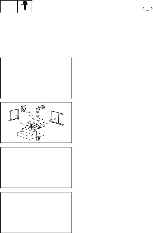
VENTILATION .......................................................................................... |
1-2 |
SELF-PROTECTION ................................................................................. |
1-2 |
OILS, GREASES AND SEALING FLUIDS ............................................... |
1-2 |
GOOD WORKING PRACTICES ............................................................... |
1-3 |
DISASSEMBLY AND ASSEMBLY ........................................................... |
1-4 |
SPECIAL TOOLS ............................................................................................ |
1-5 |
MEASURING ........................................................................................... |
1-5 |
REMOVING AND INSTALLING ............................................................... |
1-7 |

|
F |
D |
ES |
|
|
|
|
CHAPITRE 1 |
KAPITEL 1 |
|
CAPITULO 1 |
INFORMATIONS |
ALLGEMEINES |
|
INFORMACIÓN |
GENERALES |
|
|
GENERAL |
IDENTIFICATION ............................ |
1-1 |
NUMERO DE SERIE ...................... |
1-1 |
NUMEROS DE DEBUT DE SERIE 1-1 |
|
MESURES DE SECURITE EN TRA- |
|
VAILLANT ....................................... |
1-2 |
MESURES DE PREVENTION |
|
CONTRE LES INCENDIES .......... |
1-2 |
AERATION ...................................... |
1-2 |
PROTECTION PERSONNELLE .... |
1-2 |
HUILES, GRAISSES ET LIQUIDES |
|
D’ETANCHEITE ........................... |
1-2 |
BONNES PRATIQUES DE |
|
TRAVAIL ....................................... |
1-3 |
DEMONTAGE ET REMONTAGE . 1-4 |
|
OUTILLAGE SPECIAL ................... |
1-5 |
MESURE .......................................... |
1-5 |
DEPOSE ET INSTALLATION ....... |
1-7 |
KENNUMMER .............................. |
1-1 |
IDENTIFICACIÓN ............................ |
1-1 |
SERIENNUMMER ...................... |
1-1 |
NÚMERO DE SERIE ....................... |
1-1 |
ANFANGS-SERIENNUMMERN 1-1 |
NÚMEROS DE SERIE INICIALES 1-1 |
||
SICHERHEITSVORKEHRUNGEN . 1-2 |
SEGURIDAD EN EL TRABAJO ..... |
1-2 |
|
BRANDSCHUTZ ......................... |
1-2 |
PREVENCIÓN DE INCENDIOS .... |
1-2 |
BELÜFTUNG .............................. |
1-2 |
VENTILACIÓN ............................... |
1-2 |
SELBSTSCHUTZ ........................ |
1-2 |
AUTOPROTECCIÓN ...................... |
1-2 |
ÖLE, SCHMIERSTOFFE UND |
|
ACEITES, GRASAS Y LÍQUIDOS |
|
DICHTUNGSMITTEL ................ |
1-2 |
OBTURANTES .............................. |
1-2 |
RICHTIGE |
|
PROCEDIMIENTO DE TRABAJO |
|
ARBEITSGEWOHNHEITEN ...... |
1-3 |
CORRECTOS ................................. |
1-3 |
DEMONTAGE UND MONTAGE .1-4 |
DESMONTAJE Y MONTAJE ......... |
1-4 |
|
SPEZIALWERKZEUGE ................. |
1-5 |
HERRAMIENTAS ESPECIALES |
...1-5 |
MESSGERÄTE ........................... |
1-5 |
MEDICIÓN ...................................... |
1-5 |
AUSBAU UND EINBAU ............. |
1-7 |
EXTRACCIÓN E INSTALACIÓN .. |
1-7 |
1
2
3
4
5
6
7
8
9
GEN |
|
|
IDENTIFICATION |
|
INFO |
|
|
E |
|
|
|
|
|
IDENTIFICATION |
|
|
|
|
|
|
|
|
|
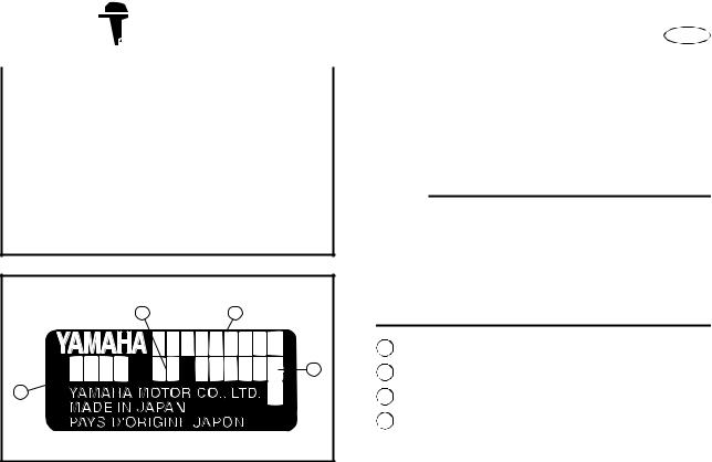
SERIAL NUMBER |
|
|
|
|
The outboard motor’s serial number is |
|
|
|
|
stamped on a label which is attached to the |
|
|
|
|
port clamp bracket. |
3 |
1 |
|
4 |
2 |
|
NOTE:
As an antitheft measure, a special label on which the outboard motor’s serial number is stamped is bonded to the port clamp bracket. The label is specially treated so that peeling it off causes cracks across the serial number.
1  Model name
2  Approval model code
3  Transom height
4  Serial number
STARTING SERIAL NUMBERS
The starting serial number blocks are as follows:
Model name |
Approval |
Starting |
||
|
|
model |
serial |
|
Worldwide |
USA, Canada |
|||
code |
number |
|||
|
|
|||
|
|
|
|
|
F40BMHD |
F40MH |
67C |
300101 |
|
|
|
|
|
|
F40BWHD |
— |
67C |
350101 |
|
|
|
|
|
|
F40BED |
F40ER |
67C |
450101 |
|
|
|
|
|
|
F40BET |
F40TR |
67C |
500101 |
|
|
|
|
|
|
1-1

|
|
|
IDENTIFICATION |
F |
GEN |
|
|
||
|
|
KENNUMMER |
D |
|
INFO |
|
|
IDENTIFICATIÓN |
ES |
IDENTIFICATION |
KENNUMMER |
IDENTIFICACIÓN |
||
NUMERO DE SERIE
Le numéro de série du moteur hors-bord est estampé sur une étiquette qui est fixée du côté bâbord du support de serrage.
N.B.:
A titre de mesure antivol, une étiquette spéciale sur laquelle est estampé le numéro de série du moteur hors-bord est attachée au support de serrage bâbord.
L’étiquette a subi un traitement spécial de sorte qu’en la décollant le numéro de série se fissure.
aNom de modèle
bCode d’agrément de modèle
cHauteur de barre d’arcasse
dNuméro de série
NUMEROS DE DEBUT DE SERIE
Les blocs numéros de début de série sont les suivants:
Nom de modéle |
Code de |
N° de |
||
Universel |
E.-U., |
modéle |
début de |
|
Canada |
agréé |
série |
||
|
||||
|
|
|
|
|
F40BMHD |
F40MH |
67C |
300101 |
|
|
|
|
|
|
F40BWHD |
— |
67C |
350101 |
|
|
|
|
|
|
F40BED |
F40ER |
67C |
450101 |
|
|
|
|
|
|
F40BET |
F40TR |
67C |
500101 |
|
SERIENNUMMER
Die Seriennummer des Außenbordmotors ist auf ein Etikett eingestanzt, das auf der BackbordSeite der Klemmhalterung angebracht ist.
HINWEIS:
Als Diebstahlsicherung ist die Seriennummer des Außenbordmotors auf ein Spezialetikett eingestanzt, das auf der Klemmhalterung auf der Backbordseite angebracht ist. Das Etikett ist speziell behandelt, so daß das Abziehen Risse über der Seriennummer hinterläßt.
aModellbezeichnung
bModell-Zulassungsnummer
cSpiegelhöhe
dSeriennummer
ANFANGS-SERIENNUMMERN
Die Nummernblöcke der AnfangsSeriennummern sind wie folgt:
Modellbezeichnung |
Geneh- |
|
||
|
|
migung |
Anfang |
|
|
USA, |
Modell- |
s-Seri- |
|
Weltweit |
Zulas- |
ennum- |
||
Kanada |
||||
|
sung- |
mer |
||
|
|
|||
|
|
snummer |
|
|
F40BMHD |
F40MH |
67C |
300101 |
|
F40BWHD |
— |
67C |
350101 |
|
|
|
|
|
|
F40BED |
F40ER |
67C |
450101 |
|
F40BET |
F40TR |
67C |
500101 |
|
NÚMERO DE SERIE
El número de serie del motor fuera borda está impreso en una etiqueta colocada a babor del soporte mordaza.
NOTA:
Como medida de seguridad, hay una etiqueta especial que tiene impreso el número de serie del motor fuera borda colocada a babor del soporte mordaza. Esta etiqueta lleva una tratamiento especial de forma que si se extrae, el número de serie queda agrietado.
aNombre del modelo
bCódigo de aprobación del modelo
cAltura del peto
dNúmero de serie
NÚMEROS DE SERIE INICIALES
Los bloques de números de serie iniciales son los siguientes:
Nombre del modelo |
Código de |
Número |
||
Interna- |
EE.UU., |
aproba- |
de serie |
|
ción del |
||||
cional |
CANADÁ |
inicial |
||
modelo |
||||
|
|
|
||
F40BMHD |
F40MH |
67C |
300101 |
|
F40BWHD |
— |
67C |
350101 |
|
F40BED |
F40ER |
67C |
450101 |
|
F40BET |
F40TR |
67C |
500101 |
|
1-1
GEN INFO
SAFETY WHILE WORKING |
E |
|
|
SAFETY WHILE WORKING
The procedures given in this manual are those recommended by Yamaha to be followed by Yamaha dealers and their mechanics.
FIRE PREVENTION
Gasoline (petrol) is highly flammable. Petroleum vapor is explosive if ignited.
Do not smoke while handling gasoline and keep it away from heat, sparks and open flames.
VENTILATION
Petroleum vapor is heavier than air and is deadly if inhaled in large quantities. Engine exhaust gases are harmful to breathe.
When test-running an engine indoors, maintain good ventilation.
SELF-PROTECTION
Protect your eyes with suitable safety glasses or safety goggles, when grinding or when doing any operation which may cause particles to fly off. Protect hands and feet by wearing safety gloves or protective shoes if appropriate to the work you are doing.
OILS, GREASES AND SEALING FLUIDS
Use only genuine Yamaha oils, greases and sealing fluids or those recommended by Yamaha.
1-2
GEN INFO
MESURES DE SECURITE EN TRAVAILLANT |
F |
SICHERHEITSVORKEHRUNGEN |
D |
SEGURIDAD EN EL TRABAJO |
ES |
|
|
MESURES DE SECURITE EN TRAVAILLANT
Les procédures décrites dans ce manuel sont recommandées par Yamaha et doivent être respectées par les concessionnaires Yamaha et leurs mécaniciens.
SICHERHEITSVORKEHRU NGEN
Die in diesem Handbuch angegebenen Maßnahmen sind von Yamaha empfohlen und von den Yamaha-Händlern und ihren Mechanikern zu beachten.
SEGURIDAD EN EL
TRABAJO
Los procedimientos incluidos en este manual son los que Yamaha recomienda a sus concesionarios y mecánicos.
PREVENCIÓN DE INCENDIOS
MESURES DE PREVENTION CONTRE LES INCENDIES
L’essence est un produit très inflammable.
Les vapeurs d’essence sont explosives lorsqu’elles sont enflammées.
Ne pas fumer lors de la manipulation d’essence. Maintenir l’essence à l’écart des sources de chaleur, des étincelles et des flammes.
AERATION
Les vapeurs d’essence sont plus lourdes que l’air et quand elles sont inhalées en grandes quantités, elles deviennent mortelles. Il est nocif d’inhaler des gaz d’échappement.
Lors d’essais de fonctionnement d’un moteur en intérieur, s’assurer que l’endroit est bien aéré.
PROTECTION PERSONNELLE
Se protéger les yeux avec des lunettes ou un masque lors d’une opération de meulage ou de toute opération durant laquelle des particules risquent d’être projetées. Se protéger également les mains et les pieds avec des gants de sécurité et des chaussures de protection si nécessaire.
BRANDSCHUTZ
Kraftstoff (Benzin) ist leicht entflammbar.
Benzindämpfe sind hochexplosiv. Kraftstoff auf gar keinen Fall in der Nähe von Funken oder Flammen handhaben. Niemals rauchen, wenn mit Kraftstoff hantiert wird.
BELÜFTUNG
Benzindämpfe sind schwerer als Luft. Bei längerem Einatmen dieser Dämpfe besteht Lebensgefahr. Das Einatmen von Motorabgasen ist gesundheitsschädlich.
Beim Probelauf eines Motors in geschlossenen Räumen, für ausreichende Belüftung sorgen.
SELBSTSCHUTZ
Bei Schleifarbeiten oder sonstigen Arbeiten, bei denen Metallsplitter oder andere Teilchen freigesetzt werden, eine geeignete Schutzbrille oder -maske aufsetzen. Zum Schutz der Hände und Füße, wenn angebracht, stets Sicherheitsschuhe und -hands- chuhe tragen.
La gasolina (petróleo) es altamente inflamable.
El vapor del petróleo es explosivo si se enciende.
No fume mientras manipula con gasolina (petróleo) y manténgala alejada del calor, chispas y llamas
VENTILACIÓN
El vapor de petróleo es más pesado que el aire y puede provocar la muerte si se inhala en grandes cantidades. La inhalación de los gases de escape del motor son perjudiciales.
Cuando compruebe el mantenimiento de un motor en un lugar cerrado, mantenga el lugar bien ventilado.
AUTOPROTECCIÓN
Protéjase los ojos con gafas adecuadas de seguridad esmerile o cuando realice cualquier operación que provoque el desprendimiento de partículas. Protéjase manos y pies con guantes de seguridad o zapatos apropiados para el trabajo a realizar.
ACEITES, GRASAS Y LÍQUIDOS OBTURANTES
Utilice siempre aceites, grasas y líquidos obturantes genuinos Yamaha, u otros
HUILES, GRAISSES ET LIQUIDES D’ETANCHEITE
N’utiliser que les huiles, les graisses ou les liquides d’étanchéité Yamaha ou ceux recommandés par Yamaha.
ÖLE, SCHMIERSTOFFE UND |
recomendados por Yamaha. |
DICHTUNGSMITTEL |
|
Nur von Yamaha hergestellte Öle, Schmierstoffe und Dichtungsmittel verwenden.
1-2

GEN INFO
SAFETY WHILE WORKING |
E |
|
|
Under normal conditions or use, there should be no hazards from the use of the lubricants mentioned in this manual, but safety is all-important, and by adopting good safety practices, any risk is minimized. A summary of the most important precautions is as follows:
1.While working, maintain good standards of per sonal and industrial hygiene.
2.Clothing which has become contaminated with lubricants should be changed as soon as practicable, and laundered before further use.
3.Avoid skin contact with lubricants; do not, for example, place a soiled wipingrag in your pocket.
4.Hands and any other part of the body which have been in contact with lubricants or lubricant-contaminated clothing, should be thoroughly washed with hot water and soap as soon as practicable.
5.To protect the skin, the application of a suitable barrier cream to the hands before working, is recommended.
6.A supply of clean lint-free cloths should be available for wiping purposes.
GOOD WORKING PRACTICES
1.The right tools
Use the recommended special tools to protect parts from damage. Use the right tool in the right manner - do not improvise.
2.Tightening torque
Follow the tightening torque instructions. When tightening bolts, nuts and screws, tighten the large sizes first, and tighten inner-positioned fixings before outer-positioned ones.
1-3

GEN INFO
MESURES DE SECURITE EN TRAVAILLANT |
F |
SICHERHEITSVORKEHRUNGEN |
D |
SEGURIDAD EN EL TRABAJO |
ES |
|
|
En conditions normales d’utilisation, il ne devrait pas y avoir de danger lié à l’utilisation des lubrifiants indiqués dans ce manuel. Néanmoins, il convient de prendre toutes les mesures de sécurité nécessaires afin de minimiser les risques. Observez les principales consignes suivantes:
1.En travaillant, respecter les règles d’hygiène personnelle et professionnelle qui s’imposent.
2.Si les vêtements ont été souillés par les lubrifiants, les changer dès que possible et les laver avant de les réutiliser.
3.Eviter le contact des lubrifiants avec la peau, ne pas mettre par exemple un chiffon imbibé de l’un de ces produits dans votre poche.
4.Si les mains ou d’autres parties du corps ont été en contact avec des lubrifiants ou des vêtements souillés par ces produits, bien les laver à l’eau chaude et au savon dès que possible.
5.Il est recommandé de se protéger les mains avec une crème appropriée avant de travailler.
6.Toujours prévoir une réserve de chiffons propres et non pelucheux.
BONNES PRATIQUES DE TRAVAIL
1.Outillage correct
Utiliser les outils spéciaux conseillés afin d’éviter d’endommager les pièces. Toujours utiliser l’outil convenant au travail à effectuer. – Ne pas improviser.
2.Couple de serrage
Respecter les couples de serrage spécifiés. Lors du serrage des boulons, des écrous ou des vis, serrer tout d’abord les fixations ayant le plus gros diamètre en allant du centre vers l’extérieur.
Unter normalen Gebrauchsbedingungen sollten die in diesem Handbuch aufgeführten Schmierstoffe keine Gefahr darstellen. Da Sicherheit jedoch oberstes Gebot ist, sollten einige Sicherheitsmaßnahmen eingehalten werden, um jegliches Risiko auf das Mindeste zu begrenzen.
Nachstehend eine Übersicht der wichtigsten Vorsichtsmaßnahmen:
1.Während der Arbeit immer für saubere, gut sitzende Arbeitskleidung und einen sauberen Arbeitsplatz sorgen.
2.Durch Schmiermittel verschmutzte Kleidung bei der ersten Gelegenheit wechseln und vor weiterer Benutzung gründlich reinigen lassen.
3.Vermeiden, Schmiermittel mit der Haut in Berührung zu bringen (z.B. ölige Lappen nicht in die Tasche stecken).
4.Hände und andere Körperteile, die in Kontakt mit Schmiermitteln oder verschmutzter Kleidung gekommen sind, möglichst schnell, gründlich mit warmem Wasser und Seife waschen.
5.Zum Schutz der Haut wird vor Arbeitsbeginn das Auftragen einer geeigneten Schutzcreme empfohlen.
6.Stets einen Vorrat fusselfreier Putztücher oder saugfähiges Papier bereithalten.
RICHTIGE ARBEITSGEWOHNHEITEN
1.Die richtigen Werkzeuge
Die Verwendung von Spezialwerkzeug trägt in erheblichem Maße dazu bei, die zu wartenden Teile vor Beschädigung zu schützen. Das Werkzeug muß in der vorgeschriebenen Art und Weise benutzt werden. – Keine Behelfsmethoden und -mittel.
2.Anzugsdrehmoment
Die Anweisungen über die Anzugsdrehmomente beachten. Beim Festziehen von Schrauben und Muttern erst die größeren Schrauben anziehen. Innenliegende Schrauben prinzipiell vor außenliegenden festziehen.
En condiciones normales de uso, el empleo de los lubricantes mencionados en este manual no debe plantear ningún riesgo, pero la seguridad es un tema de máxima importancia, por lo que la adopción de algunas medidas de seguridad puede reducir los posibles riesgos. A continuación se incluye un resumen de las precauciones más importantes:
1.Cuando trabaje, mantenga una higiene personal e industrial correcta.
2.La ropa contaminada con lubricante debe cambiarse tan pronto como sea posible y lavarse antes de volver a usarla.
3.Evite el contacto de la piel con los l u b r i c a n t e s , p o r ej e m p l o , n o introduzca un trapo impregnado en el bolsillo.
4.Las manos y cualquier otra parte del cuerpo que haya estado en contacto con lubricantes o ropa contaminada por lubricantes deben lavarse minuciosamente con agua caliente y jabón tan pronto como sea posible.
5.Para proteger la piel, se recomienda aplicar una crema protectora apropiada en las manos antes de iniciar el trabajo.
6.Debe disponer de paños limpios que no dejen pelusa para fines de limpieza.
PROCEDIMIENTO DE TRABAJO CORRECTOS
1.Las herramientas correctas
Utilice las herramientas especiales recomendadas para evitar dañar las piezas. Utilice la herramienta correcta de la manera apropiada – no improvise.
2.Torsión de apriete
Siga las instrucciones relacionadas con la torsión de apriete . Cuando apriete pernos, tuercas y tornillos, apriete en primer lugar los de mayor tamaño y apriete los situados en la parte interior antes de apretar los situados en la parte exterior.
1-3
GEN INFO
SAFETY WHILE WORKING |
E |
|
|
3.Non-reusable items
Always use new gaskets, packings, O- rings, split-pins, circlips, etc., on reassembly.
DISASSEMBLY AND ASSEMBLY
1.Clean parts with compressed air when disassembling.
2.Oil the contact surfaces of moving parts before assembly.
3.After assembly, check that moving parts operate normally.
4.Install bearings with the manufacturer’s markings on the side exposed to view, and liberally oil the bearings.
5.When installing oil seals, apply a light coating of water-resistant grease to the outside diameter.
1-4

GEN INFO
MESURES DE SECURITE EN TRAVAILLANT |
F |
SICHERHEITSVORKEHRUNGEN |
D |
SEGURIDAD EN EL TRABAJO |
ES |
|
|
3.Pièces à usage unique
Lors du remontage, toujours utiliser des joints, garnitures, joints toriques, goupilles fendues, circlips, etc. neufs.
DEMONTAGE ET REMONTAGE
1.Nettoyer les pièces à l’air comprimé lors du démontage.
2. Lors du montage, huiler les sur- f a c e s d e c o n t a c t d e s p i è c e s mobiles.
3.Après le montage, vérifier que les pièces mobiles fonctionnent normalement.
4. Monter les roulements avec la m a r q u e d u f a b r i c a n t v e r s l’extérieur et les huiler généreusement.
5.Lors du montage des joints à huile, appliquer une légère couche de graisse hydrofuge sur le diamètre extérieur.
3.Nicht wiederverwendbare Teile
Beim Wiedereinbau stets neue Dichtungen, Dämmstoffe, O - Ringe, Splinte, Sicherungsringe usw. verwenden.
DEMONTAGE UND MONTAGE
1.Ausgebaute Teile mit Druckluft reinigen.
2.Kontaktflächen beweglicher Teile beim Einbau mit Öl schmieren.
3.Nach der Montage bewegliche Teile auf gute Funktion prüfen.
4.Lager so einsetzen, daß die Herstellerkennzeichen sichtbar bleiben. Lager großzügig schmieren.
5.Beim Einbau von Wellendichtungen, diese außen leicht mit einer dünnen Schicht wasserbeständigen Fetts versehen.
3.Elementos no reutilizables
Utilice siempre empaquetaduras, juntas tóricas, pasadores hendidos, retenedores etc, nuevos cuando vuelva a montar los componentes.
DESMONTAJE Y MONTAJE
1.Limpie las piezas con aire comprimido al desmontarlas.
2.Engrase las superficies de contacto de las piezas móviles antes de montarlas.
3.Tras el montaje, compruebe que las piezas móviles funcionan con normalidad.
4.Instale los cojinetes con las marcas del fabricante encaradas hacia el lado que queda expuesto a la vista y engráselo abundantemente.
5.Cuando instale sellos de aceite, aplique una capa de grasa hidrófuga en el diámetro exterior.
1-4
GEN |
SPECIAL TOOLS |
|
INFO |
E |
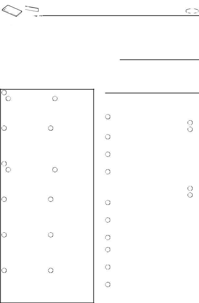
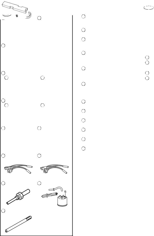
SPECIAL TOOLS
1 
a |
b |
2 |
3 |
4 
a |
b |
|
|
|
|
5 |
6 |
7 |
8 |
9 |
10 |
Using the correct special tools recommended by Yamaha, will aid the work and enable accurate assembly and tune-up.
Improvising and using improper tools can damage the equipment.
NOTE:
•For U.S.A. and Canada, use part numbers that start with "J-", "YB-", "YM-", "YU-" or "YW-".
•For other countries, use part numbers that start with "90890-".
MEASURING
1 |
Tachometer |
|
|
P/N. YU-08036-A ............................ |
a |
|
90890-06760 ........................... |
b |
2 |
Pressure tester |
|
|
P/N. YB-03595 |
|
|
90890-06762 |
|
3 |
Mity vac |
|
|
P/N. YB-35956 |
|
|
90890-06756 |
|
4 |
Pinion height gauge |
|
|
P/N. YB-34432-8, YB-34432-9, |
|
|
YB-34432-10, YB-34432-11, |
|
|
YB-34432-17 ........................... |
a |
|
90890-06702 ........................... |
b |
5  Dial gauge set P/N. YU-03097
90890-01252
6  Magnetic base P/N. YU-34481
90890-06705
7  Digital caliper P/N. 90890-06704
8  Backlash indicator P/N. YB-06265
90890-06706
9  Magnetic base attaching plate P/N. YB-07003
90890-07003
10 Compression gauge P/N. YU-33223
90890-03160
1-5
GEN INFO
OUTILLAGE SPECIAL |
F |
SPEZIALWERKZEUGE |
D |
HERRAMIENTAS ESPECIALES |
ES |
|
|
OUTILLAGE SPECIAL
Pour une plus grande précision dans votre travail de montage et de mise au point, Yamaha vous recommande l’emploi d’outils spéciaux. Les improvisations ou l’utilisation d’outils non appropriés peuvent endommager le matériel.
N.B.:
•Pour les E.-U. et le Canada, utiliser les pièces dont la référence commence par “J-”, “YB-”, “YM-”, “YU-” ou “YW-”.
•Pour les autres pays, utiliser les pièces dont la référence commence par “90890-”.
MESURE
SPEZIALWERKZEUGE
Die Verwendung der von Yamaha empfohlenen Spezialwerkzeuge erleichtert die Arbeit und ermöglicht genaue Montage und Einstellung. Behelfsmethoden und falsches Werkzeug hingegen können erhebliche Schäden am Material verursachen.
HINWEIS:
•Werkzeugnummern, die mit “J-”, “YB-”, “YM-”, “YU-” oder “YW-” beginnen, beziehen sich auf die USA und Kanada.
•Für andere Länder gelten die Teilenummern, die mit “90890-” beginnen.
HERRAMIENTAS
ESPECIALES
La utilización de las herramientas especiales recomendadas por Yamaha le ayudará en el trabajo y asegurará un montaje y puesta a punto con precisión. La improvisación y el empleo de herramientas incorrectas puede dañar el equipo.
NOTA:
•Para EE.UU y Canadá, utilice los números de pieza que empiecen por “J-”, “YB-”, “YM-”, “YU-” o “YW-”.
•Para otros países, utilice los números de piezas que empiecen por “90890-”.
aCompte-tours
P/N. YU-08036-A .............. a 90890-06760 .............. b
bTesteur de pression P/N. YB-03595
90890-06762
cMity vac
P/N. YB-35956 90890-06756
dJauge de hauteur de pignon P/N. YB-34432-8,
YB-34432-9, YB-34432-10, YB-34432-11, YB-34432-17 ............ a 90890-06702 .............. b
eEnsemble pour jauge de cylindre P/N. YU-03097
90890-01252
fBase magnétique P/N. YU-34481
90890-06705
gPied à coulisse numérique P/N. 90890-06704
hIndicateur de jeu de retour P/N. YB-06265
90890-06706
iPlaque de fixation de base magnétique
P/N. YB-07003 90890-07003
jCompressiomètre P/N. YU-33223
90890-03160
MESSGERÄTE
aTachometer
P/N. YU-08036-A............ a 90890-06760........... b
bDrucktester P/N. YB-03595
90890-06762
cMity vac
P/N. YB-35956 90890-06756
dRitzelhöhenmesser P/N. YB-34432-8,
YB-34432-9, YB-34432-10, YB-34432-11, YB-34432-17 .......... a 90890-06702........... b
eMeßuhr-Satz P/N. YU-03097
90890-01252
fMagnetische Basis P/N. YU-34481
90890-06705
gDigitale Schiebelehre P/N. 90890-06704
hRückschlagsanzeiger P/N. YB-06265
90890-06706
iVerbindungsplatte für die magnetische Basis
P/N. YB-07003 90890-07003
jKompressionsmesser P/N. YU-33223
90890-03160
MEDICIÓN
aTacómetro
P/N.° YU-08036-A .............. a 90890-06760 .............. b
bProbador de presión P/N.° YB-03595
90890-06762
cMity vac
P/N.° YB-35956 90890-06756
dMedidor de altura de piñón P/N.° YB-34432-8,
YB-34432-9, YB-34432-10, YB-34432-11, YB-34432-17 ............ a 90890-06702 .............. b
eCalibre de cuadrante P/N.° YU-03097
90890-01252
fBase magnética P/N.° YU-34481
90890-06705
gCalibrador digital P/N.° 90890-06704
hIndicador de contragolpe P/N.° YB-06265
90890-06706
iPlaca de colocación de la base magnética
P/N.° YB-07003 90890-07003
jManómetro de compresión P/N.° YU-33223
90890-03160
1-5
GEN |
|
|
SPECIAL TOOLS |
|
|
|
INFO |
|
|
|
E |
||
|
|
|
|
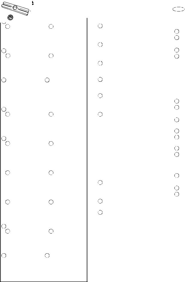
11 |
Vacuum gauge set |
|
11 |
12 |
|||||
|
P/N. YU-08030 |
|||||
|
|
|
|
|
||
|
|
|
|
|
90890-03159 |
|
|
|
|
|
12 |
Feeler gauge |
|
|
|
|
|
|
P/N. YU-26900-9 |
|
|
|
|
|
13 |
Digital tester |
|
13 |
|
|
|
|
P/N. J-39299 |
|
|
|
|
|
90890-06752 |
||
|
|
|
|
|
||
|
|
|
|
14 |
Peak voltage adapter |
|
|
|
|
|
|
P/N. YU-39991................................ a |
|
|
|
|
|
|
90890-03169 ........................... b |
|
|
|
|
|
15 |
Spark gap tester |
|
14 |
|
|
|
|
P/N. YM-34487 ............................... a |
|
a |
|
|
b |
|
90890-06754 ........................... b |
|
|
|
|
|
16 |
Shimming gauge |
|
|
|
|
|
|
P/N. YB-34446-1, YB-34446-3, |
|
|
|
|
|
|
YB-34446-4, YB-34446-5, |
|
|
|
|
|
|
YB-34446-7 |
|
15 |
|
|
|
17 |
Shimming plate |
|
a |
|
|
b |
|
P/N. 90890-06701 |
|
|
|
|
|
18 |
2 Pins test harness |
|
|
|
|
|
|
P/N. 90890-06767 |
|
|
|
|
|
19 |
2 Pins test harness |
|
16 |
17 |
|
P/N. 90890-06768 |
|||
20 |
Exhaust gas probe |
|||||
|
|
|
|
|||
|
|
|
|
|
P/N. 90890-03161 |
|
|
|
|
|
21 |
Surge tank set |
|
|
|
|
|
|
P/N. 90890-03162 |
|
|
|
|
|
22 |
Pilot screw driver |
|
18 |
19 |
|
P/N. 90890-03154 |
|||
|
|
|||||
20 |
21 |
22
1-6

GEN INFO
OUTILLAGE SPECIAL |
F |
SPEZIALWERKZEUGE |
D |
HERRAMIENTAS ESPECIALES |
ES |
|
|
kSet pour jauge de dépression P/N. YU-08030
90890-03159
lJauge d’épaisseur P/N. YU-26900-9
mTesteur numérique P/N. J-39299
90890-06752
nAdaptateur de tension de crête P/N. YU-39991 .................. a 90890-03169 .............. b
oTesteur d’allumage
P/N. YM-34487.................. a 90890-06754 .............. b
pJauge de mesure de cale
P/N. YB-34446-1, YB-34446-3, YB-34446-4, YB-34446-5, YB-34446-7
qPlaque de mesure de cale P/N. 90890-06701
rFaisceau de test à 2 broches P/N. 90890-06767
sFaisceau de test à 2 broches P/N. 90890-06768
tSonde des gaz d’échappement P/N. 90890-03161
uJeu de réservoir tampon P/N. 90890-03162
vChassoir de vis de ralenti P/N. 90890-03154
kVakuummeßinstrumentensatz
P/N. YU-08030 90890-03159
lFühlerlehre
P/N. YU-26900-9
mDigitales Schaltkreisprüfgerät P/N. J-39299
90890-06752
nSpitzenspannungsadapter P/N. YU-39991 ............... a 90890-03169........... b
oZündfunkentester
P/N. YM-34487............... a 90890-06754........... b
pAusgleichslehre P/N. YB-34446-1, YB-34446-3, YB-34446-4, YB-34446-5, YB-34446-7
qAusgleichsplatte P/N. 90890-06701
rPrüfkabelbaum, 2polig P/N. 90890-06767
sPrüfkabelbaum, 2polig P/N. 90890-06768
tAbgas-Prüfsonde P/N. 90890-03161
uÜberlaufbehälter-Teilesatz P/N. 90890-03162
vSchraubendreher für Leer- lauf-Einstellschraube
P/N. 90890-03154
kJuego del vacuómetro P/N.° YU-08030
90890-03159
lCalibre de espesores P/N.° YU-26900-9
mProbador digital P/N.° J-39299
90890-06752
nAdaptador de la tensión de pico P/N.° YU-39991 .................. a 90890-03169 .............. b
oProbador de chispas
P/N.° YM-34487.................. a 90890-06754 .............. b
pMedidor de laminillas
P/N.° YB-34446-1, YB-34446-3, YB-34446-4, YB-34446-5, YB-34446-7
qPlaca de laminillas P/N.° 90890-06701
rMazo de cables de prueba de 2 contactos
P/N.° 90890-06767
sMazo de cables de prueba de 2 contactos
P/N.° 90890-06768
tSonda para el gas de escape P/N.° 90890-03161
uJuego de cámara de compensación P/N.° 90890-03162
vDestornillador piloto P/N.° 90890-03154
1-6
GEN |
|
|
SPECIAL TOOLS |
|
|
|
||
INFO |
|
|
|
|
E |
|||
|
|
|
|
|
|
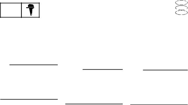
REMOVING AND INSTALLING |
|
|
1 |
|
|
|
|
|
|
||
|
|
|
|
|
1 |
Flywheel magnet assembly holder |
|
|
a |
|
b |
|
|||||
|
|
|
|
|
|
|
P/N. YB-06139 ................................ |
a |
|
|
|
|
|
|
|
90890-06522 ........................... |
b |
|
|
|
|
|
|
2 |
Universal puller |
|
2 |
|
|
|
|
|
|
P/N. YB-06117................................. |
a |
a |
|
b |
|
90890-06521 ........................... |
b |
|||
|
|
|
|
|
|
3 |
Driver rod |
|
|
|
|
|
|
|
|
P/N. YB-06071 |
|
|
|
|
|
|
|
|
90890-06652, 90890-06606 |
|
3 |
|
|
4 |
|
|
4 |
Driver rod SS |
|
|
|
|
|
|
|
|
P/N. YB-06071 |
|
|
|
|
|
|
|
|
|
|
|
|
|
|
|
|
|
90890-06604 |
|
|
|
|
|
|
|
5 |
Bearing/oil seal attachment |
|
|
|
|
|
|
|
|
P/N. YB-06063, YB-06112 ............... |
a |
5 |
|
|
|
|
|
|
90890-06614, 90890-06611 |
b |
|
|
|
|
|
|
|||
|
|
|
|
|
|
|
|
|
a |
|
b |
6 |
Bearing/oil seal attachment |
|
|||
|
|
|
|
|
|
|
P/N. YB-06276-A............................. |
a |
|
|
|
|
|
|
|
YB-41446, YB-06610, |
|
|
|
|
|
|
|
|
90890-06622, 90890-06627.... |
b |
6 |
|
|
|
|
|
|
YB-06111 ................................. |
c |
a |
|
b |
|
YB-06168 |
|
|||
|
|
|
|
|
|
|
90890-06637 ........................... |
d |
|
|
|
|
|
|
|
YB-06270-A ............................ |
e |
|
|
|
|
|
|
|
YB-06276-B |
|
|
|
|
|
|
|
|
90890-06641, 90890-06614, |
|
c |
|
d |
|
90890-06644, 90890-06659, |
|
|||
|
|
90890-06640 |
f |
|||||
|
|
|
|
|
|
|
||
|
|
|
|
|
|
7 |
Bearing separator |
|
|
|
|
|
|
|
|
P/N. YB-06219 ................................ |
a |
|
|
|
|
|
|
|
90890-06534 ........................... |
b |
e |
|
f |
8 |
Guide plate stand |
|
|||
|
|
|
|
|
|
|
P/N. 90890-06538 |
|
|
|
|
|
|
|
9 |
Guide plate |
|
|
|
|
|
|
|
|
P/N. 90890-06501 |
|
7 |
|
|
|
|
|
|
|
|
a |
|
b |
|
|
|
|||
8 |
9 |
1-7
Loading...