

Page 1

OWNER’S MANUAL
F25B
T25B
U.S.A.Edition
LIT-18626-05-06
Page 2
Page 3

EMU01449
TO THE OWNER
Thank you for choosing a Yamaha outboard
motor. This Owner’s manual contains information needed for proper operation, maintenance and care. A thorough understanding
of these simple instructions will help you
obtain maximum enjoyment from your new
Yamaha. If you have any question about the
operation or maintenance of your outboard
motor, please consult a Yamaha dealer.
In this Owner’s Manual particularly important
information is distinguished in the following
ways.
The Safety Alert Symbol means
ATTENTION! BECOME ALERT!
Q
YOUR SAFETY IS INVOLVED!
E
cC
A CAUTION indicates special precautions
that must be taken to avoid damage to
the outboard motor.
NOTE:
A NOTE provides key information to make
procedures easier or clearer.
* Yamaha continually seeks advancements
in product design and quality. Therefore,
while this manual contains the most current product information available at the
time of printing, there may be minor discrepancies between your machine and this
manual. If there is any question concerning this manual, please consult your
Yamaha dealer.
w
Failure to follow WARNING instructions
could result in severe injury or death to
the machine operator, a bystander, or a
person inspecting or repairing the outboard motor.
EMU01446
F25B, T25B
OWNER’S MANUAL
©2002 by Yamaha Motor Corporation, USA
1st Edition, April 2002
All rights reserved.
Any reprinting or unauthorized use
without the written permission of
Yamaha Motor Corporation, USA
is expressly prohibited.
Printed in Japan
P/N LIT-18626-05-06
NOTE:
The F25MH, T25TR and their standard
accessories are used as a base for the
explanations and illustrations in this manual.
Therefore, some items may not apply to
every model.
Page 4

Page 5
EMU00003
E
CONTENTS
GENERAL INFORMATION
BASIC COMPONENTS
OPERATION
MAINTENANCE
1
2
3
4
TROUBLE RECOVERY
INDEX
READ THIS OWNER’S MANUAL CAREFULLY
BEFORE OPERATING YOUR OUTBOARD MOTOR.
5
6
Page 6

Page 7
E
EMU00004
Chapter 1
GENERAL
INFORMATION
IDENTIFICATION NUMBERS RECORD ..1-1
Outboard motor serial number...........1-1
Key number...........................................1-1
EMISSION CONTROL INFORMATION...1-2
SAFETY INFORMATION..........................1-4
1
2
IMPORTANT LABELS ..............................1-6
BASIC BOATING RULES .........................1-7
FUELING INSTRUCTIONS.....................1-11
Gasoline (Petrol).................................1-12
ENGINE OIL ............................................1-13
BATTERY REQUIREMENT ....................1-14
PROPELLER SELECTION .......................1-15
START-IN-GEAR PROTECTION ............1-16
3
4
5
6
Page 8
E
401013
q
YAMAHA
EMU00005
IDENTIFICATION NUMBERS
RECORD
EMU00007
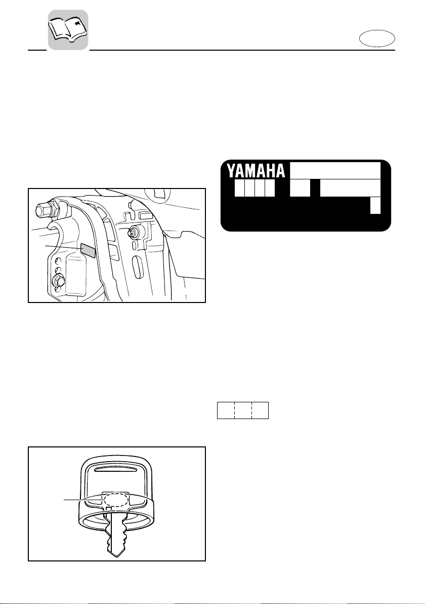
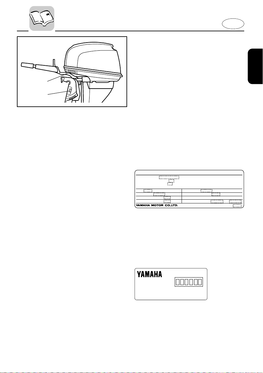
OUTBOARD MOTOR SERIAL
NUMBER
YAMAHA MOTOR CO., LTD.
MADE IN JAPAN
PAYS D'ORIGINE JAPON
The outboard motor serial number is
stamped on the label attached to the port
side of the clamp-bracket.
Record your outboard motor serial number in the spaces provided to assist you in
ordering spare parts from your Yamaha
dealer or for reference in case your outboard motor is stolen.
q
123
1 Outboard motor serial number
EMU00008
KEY NUMBER
If a main key switch is equipped with the
motor, the key identification number is
stamped on your key as shown in the
illustration. Record this number in the
space provided for reference in case you
need a new key.
1 Key number
904011*
1-1
Page 9
q
EMISSION CONTROL INFORMATION
ENGINE FAMILY :
THIS ENGINE CONFORMS TO 2001 U.S. EPA REGULATIONS FOR MARINE SI ENGINES.
THIS ENGINE CONFORMS TO 2001 CALIFORNIA EMISSION REGULATIONS FOR SI MARINE ENGINES.
REFER TO THE OWNERS MANUAL FOR MAINTENANCE SPECIFICATIONS AND ADJUSTMENTS.
FELs :
SPARK PLUG :
DISPLACEMENT :
ADVERTISED POWER :
IDLE SPEED :
SPARK PLUG GAP (mm) :
FUEL : GASOLINE
VALVE LASH (mm) :
IN EX
cm
kw
g/kw-hr
rpm IN NEUTRAL
3
EM
Manufactured:
w
E
EMU01385
EMISSION CONTROL
INFORMATION
EMU01387
NORTH AMERICAN MODELS
This engine conforms to U.S. Environmental Protection Agency (EPA) regulations for marine SI engines. See the label
affixed to your engine for details.
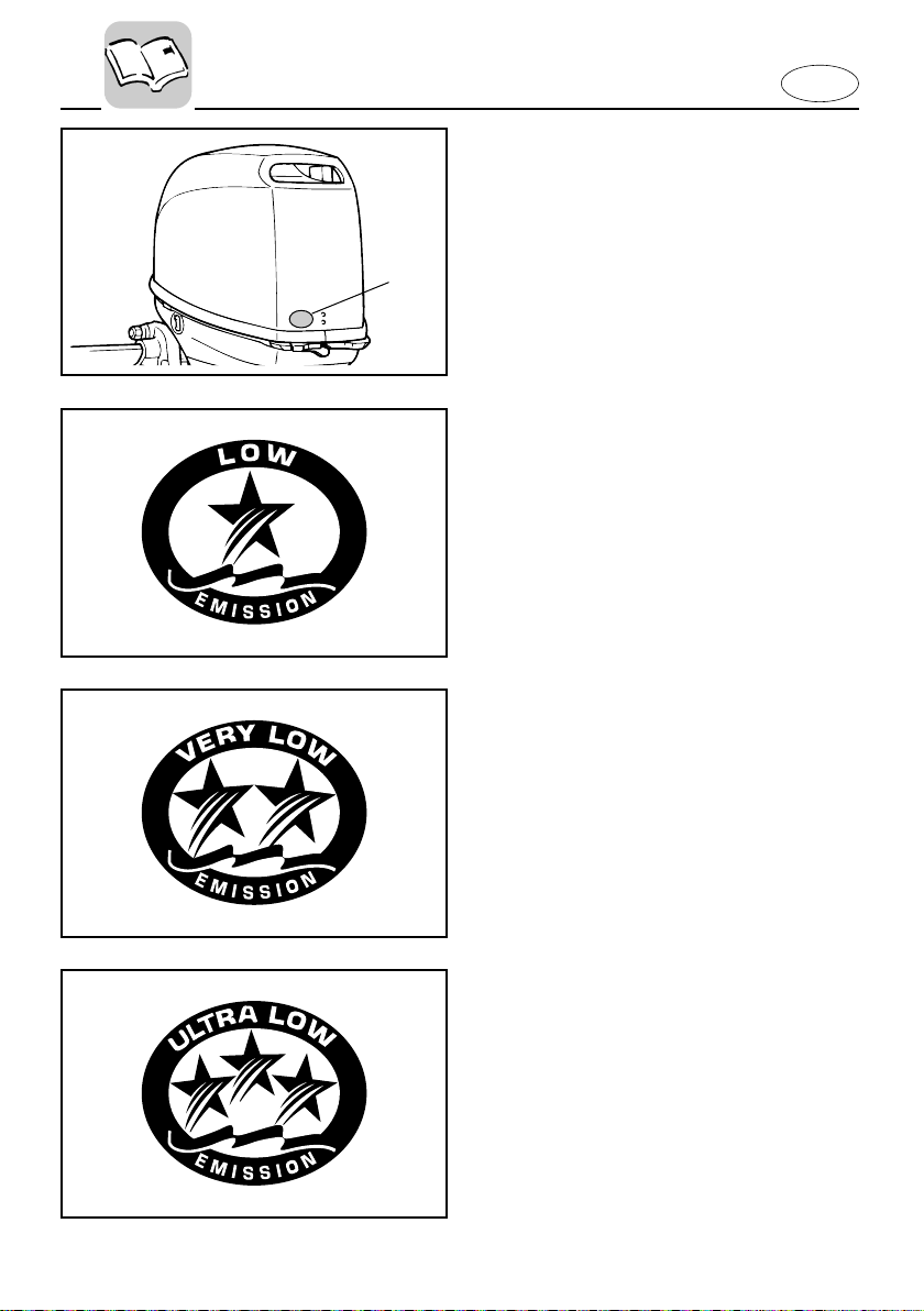
Approval label of Emission control
certificate
This label is attached to the bottom cowling.
1 Emission control information label
New Technology ; (4-stroke) EM
Manufactured date label
This label is attached to the clamp bracket.
2 Manufactured date label
1-2
Page 10
q
000853
E
EMU01389
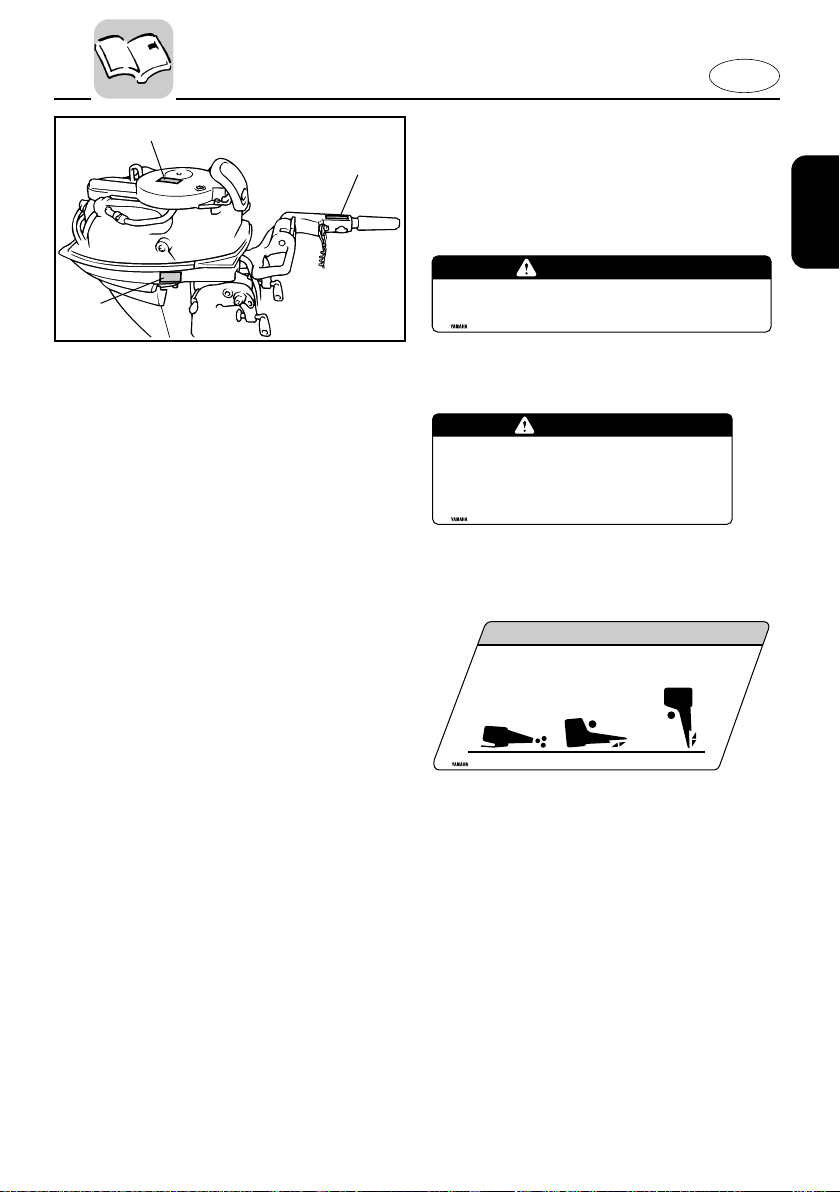
STAR LABELS
Your outboard motor is labeled with a
California Air Resources Board (CARB)
star label. See below for a description of
your particular label.
1 Star label
One Star - Low Emission
The one-star label identifies engines that
meet the Air Resources Board’s 2001
exhaust emission standards. Engines
meeting these standards have 75% lower
emissions than conventional carbureted
two-stroke engines. These engines are
equivalent to the U.S. EPA’s 2006 standards for marine engines.
Two Stars - Very Low Emission
The two-star label identifies engines that
meet the Air Resources Board’s 2004
exhaust emission standards. Engines
meeting these standards have 20% lower
emissions than One Star-Low-Emission
engines.
Three Stars - Ultra Low Emission
The three-star label identifies engines that
meet the Air Resources Board’s 2008
exhaust emission standards. Engines
meeting these standards have 65% lower
emissions than One Star-Low-Emission
engines.
1-3
Page 11

E
EMU00917
SAFETY
Q
8 Before mounting or operating the out-
board motor, read this entire manual.
Reading it should give you an understanding of the motor and its operation.
8 Before operating the boat, read any
owner’s or operator’s manuals supplied
with it and all labels. Be sure you understand each item before operating.
8 Do not overpower the boat with this
outboard motor. Overpowering the
boat could result in loss of control. The
rated power of the outboard should be
equal to or less than the rated horsepower capacity of the boat. If the rated
horsepower capacity of the boat is
unknown, consult the dealer or boat
manufacturer.
8 Do not modify the outboard. Modifica-
tions could make the motor unfit or
unsafe to use.
8 Never operate after drinking alcohol or
taking drugs. About 50% of all boating
fatalities involve intoxication.
8 Have an approved personal flotation
device (PFD) on board for every occupant. It is a good idea to wear a PFD
whenever boating. At a minimum, children and non-swimmers should always
wear PFDs, and everyone should wear
PFDs when there are potentially hazardous boating conditions.
8 Gasoline is highly flammable, and its
vapors are flammable and explosive.
Handle and store gasoline carefully.
Make sure there are no gas fumes or
leaking fuel before starting the engine.
INFORMATION
8 This product emits exhaust gases which
contain carbon monoxide, a colorless,
odorless gas which may cause brain
damage or death when inhaled. Symptoms include nausea, dizziness, and
drowsiness. Keep cockpit and cabin
areas well ventilated. Avoid blocking
exhaust outlets.
8 Check throttle, shift, and steering for
proper operation before starting the
engine.
8 Attach the engine stop switch lanyard
to a secure place on your clothing, or
your arm or leg while operating. If you
accidentally leave the helm, the lanyard
will pull from the switch, stopping the
engine.
8 Know the marine laws and regulations
where you will be boating - and obey
them. Refer to the “RULES OF THE
ROAD” section for basic boating rules.
8 Stay informed about the weather.
Check weather forecasts before boating.
Avoid boating in hazardous weather.
8 Tell someone where you are going:
leave a Float Plan with a responsible
person. Be sure to cancel the Float Plan
when you return.
8 Use common sense and good judgment
when boating. Know your abilities, and
be sure you understand how your boat
handles under the different boating
conditions you may encounter. Operate
within your limits, and the limits of your
boat. Always operate at safe speeds,
and keep a careful watch for obstacles
and other traffic.
8 Always watch carefully for swimmers
during the engine operation.
8 Stay away from swimming areas.
8 When a swimmer is in the water near
you shift into neutral and shut off the
engine.
1-4
Page 12

8 Be informed about boating safety. Addi-
tional publications and information can
be obtained from many organizations,
including the following:
United States Coast Guard
Consumer Affairs Staff (G-BC)
Office of Boating, Public, and Consumer
Affairs
U.S. Coast Guard Headquarters
Washington, D.C. 20593-0001
Boating Safety Hotline: 1-800-368-5647
National Marine Manufacturers
Association (NMMA)
401 N. Michigan Ave.
Chicago, Il 60611
Marine Retailers Association of America
155 N. Michigan Ave.
Chicago, Il 60601
E
1-5
Page 13
EMU00014
202054*
w
e
q
IMPORTANT LABELS
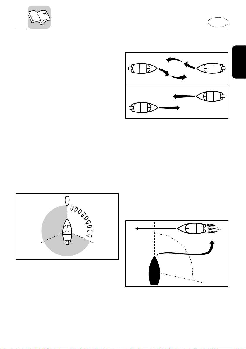
WARNING LABELS
1
E
This engine is equipped with a neutral starting device.
The engine will not start unless the shift control is
in neutral position.
6E0-83627-41
2
WARNING
WARNING
7Be sure shift control is in neutral
before starting engine. (except 2HP)
7Do not touch or remove electrical parts
when starting or during operation.
7Keep hands,hair,and clothes away from flywheel
and other rotating parts while engine is running.
6A1-83625-41
CAUTION LABELS
3
CAUTION
Tr ansport and store the engine only as shown.
Otherwise, engine damage could result from
leaking oil.
6G8-13444-41
1-6
Page 14

E
EMU00015
BASIC BOATING RULES
(Rules of the road)
Just as there are rules which apply when
you are driving on streets and high ways,
there are waterway rules which apply
when you are driving your boat. These
rules are used internationally, and are
also enforced by the United States Coast
Guard and local agencies. You should be
aware of these rules, and follow them
whenever you encounter another vessel
on the water.
Several sets of rules prevail according to
geographic location, but are all basically
the same as the International Rules of the
Road. The rules presented here in your
Owner’s Manual are condensed, and have
been provided for your convenience only.
Consult your local U.S. Coast Guard Auxiliary or Department of Motor Vehicles for
a complete set of rules governing the
waters in which you will be using your
boat.
STEERING AND SAILING RULES AND
SOUND SIGNALS
Whenever two vessels on the water meet
one another, one vessel has the right-ofway; it is called the “stand-on” vessel.
The vessel which does not have the rightof-way is called the “give-way” or “burdened” vessel. These rules determine
which vessel has the right-of-way, and
what each vessel should do.
Stand-on vessel
The vessel with the right-of-way has the
duty to continue its course and speed,
except to avoid an immediate collision.
When you maintain your direction and
speed, the other vessel will be able to
determine how best to avoid you.
Give-way vessel
The vessel which does not have the rightof-way has the duty to take positive and
timely action to stay out of the way of the
Stand-On vessel. Normally, you should
not cross in front of the vessel with the
right-of-way. You should slow down or
change directions briefly and pass behind
the other vessel. You should always move
in such a way that the operator of the
other vessel can see what you are doing.
“The general prudential rule”
This rule is called Rule 2 in the International Rules and says,
‘In obeying and construing these rules
due regard shall be had to all dangers of
navigation and collision, and to any special circumstances, which may render a
departure from the above rules necessary
in order to avoid immediate danger.’
In other words, follow the standard rules
except when a collision will occur unless
both vessels try to avoid each other. If
that is the case, both vessels become
“Give-Way” vessels.
1-7
Page 15
E
102045
RULES WHEN ENCOUNTERING
VESSELS
There are three main situations which you
may encounter with other vessels which
could lead to a collision unless the Steering Rules are followed:
Meeting (you are approaching another
vessel head-on)
Crossing (you are traveling across the
other vessel’s path)
Overtaking (you are passing or being
passed by another vessel)
In the following illustration, your boat is
in the center. You should give the right-ofway to any vessels shown in white area
(you are the Give-Way vessel). Any vessels in the shaded area must yield to you
(they are the Give-Way vessels). Both you
and the meeting vessel must alter course
to avoid each other.
will clear one another if you continue on
your set course and speed.
102044
Crossing
When two power driven vessels are
crossing each other’s path close enough
to run the risk of collision, the vessel
which has the other on the starboard
(right) side must keep out of the way of
the other. If the other vessel is on your
right, you must keep out of its way; you
are the Give-Way vessel. If the other vessel is on your port (left) side, remember
that you should maintain course and
direction, provided the other vessel gives
you the right-of-way as it should.
Meeting
If you are meeting another power vessel
head on, and are close enough to run the
risk of collision, neither of you has the
right-of-way! Both of you should alter
course to avoid an accident. You should
keep the other vessel on your port (left)
side. This rule doesn’t apply if both of you
102046
Overtaking
If you are passing another vessel, you are
the “Give-Way” vessel. This means that
the other vessel is expected to maintain
1-8
Page 16

E
its course and speed. You must stay out
of its way until you are clear of it. Likewise, if another vessel is passing you, you
should maintain your speed and direction
so that the other vessel can steer itself
around you.
OTHER SPECIAL SITUATIONS
There are three other rules you should be
aware of when driving your boat around
other vessels.
Narrow channels and bends
When navigating in narrow channels, you
should keep to the right when it is safe
and practical to do so. If the operator of a
power-driven vessel is preparing to go
around a bend that may obstruct the view
of other water vessels, the operator
should sound a prolonged blast on the
whistle (4 to 6 seconds). If another vessel
is around the bend, it too should sound
the whistle. Even if no reply is heard,
however, the vessel should still proceed
around the bend with caution. If you navigate such waters with your boat, you will
need to carry a portable air horn, available from local marine supply stores.
Fishing vessel right-of-way
All vessels which are fishing with nets,
lines or trawls are considered to be “fishing vessels” under the International
Rules. Vessels with trolling lines are not
considered fishing vessels. Fishing vessels have the right-of-way regardless of
position. Fishing vessels cannot, however, impede the passage of other vessels in
narrow channels.
Sailing vessel right-of-way
Sailing vessels should normally be given
the right-of-way. The exceptions to this
are:
1. When the sailing vessel is overtaking
the power-driven vessel, the powerdriven vessel has the right-of-way.
2. Sailing vessels should keep clear of
any fishing vessel.
3. In a narrow channel, a sailing vessel
should not hamper the safe passage
of a power-driven vessel which can
navigate only in such a channel.
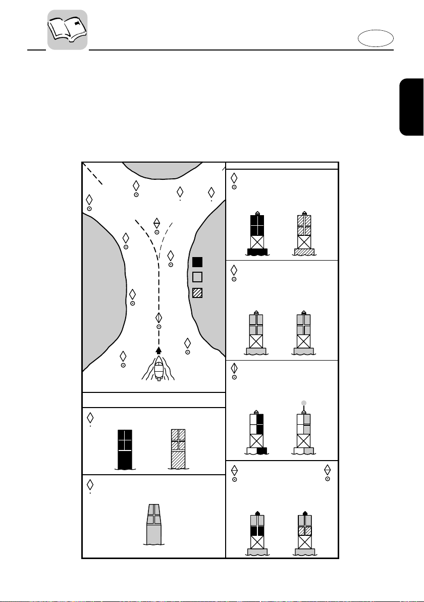
Reading buoys and other markers
The waters of the United states are
marked for safe navigation by the lateral
system of buoyage. Simply put, buoys
and markers have an arrangement of
shapes, colors, numbers and lights to
show which side of the buoy a boater
should pass on when navigating in a particular direction. The markings on these
buoys are oriented from the perspective
of being entered from seaward (the
boater is going towards the port). This
means that red buoys are passed on the
starboard (right) side when proceeding
from open water into port, and black
buoys are to port (left) side. When navigating out of port, your position with
respect to the buoys should be reversed;
red buoys should be to port and black
buoys to starboard.
Many bodies of water used by boaters are
entirely within the boundaries of a particular state. The Uniform State Waterway
Marking System has been devised for
these waters. This system uses buoys and
signs with distinctive shapes and colors
to show regulatory or advisory informa-
1-9
Page 17
1
1
A
1
1
Proceeding toward head
of navigation from seaward
CAN BUOY
Odd number. Leave to port.
OR
SECONDARY CHANNEL BUOYS
STARTS NEW NUMBERING SYSTEM
old new
C " 1
"
NUN BUOY
Even number. Leave to starboard
N
"
2
"
No change
BUOY
COLOR CODE
BLACK
RED
GREEN
"
A
"
"
2
"
"
1
"
"
3
"
"
4
"
"
5
"
"
7
"
N
"
2
"
"
6
"
C
"
1
"
RB
"
L
"
RG
"
L
"
or
SECONDARY CHANNEL
MAIN CHANNEL
old
new
2
2
2
A
L
L
Odd number. increasing toward head of naviga-
MAIN CHANNEL BUOYS
"
1
" "
3
" "
5
" "
7
"
tion.Leave to port (left) proceeding upstream.
LIGHTED BUOY (Port Hand)`
White Light
Green Light
old
new
old
new
old
new
LIGHTED BUOY (Starboard Hand)`
"
2
" "
4
" "
6
"
Even number,increasing toward head of navigation. Leave to starboard (right) proceeding upstream.
White Light Red Light
"
A
"
LIGHTED SAFE WATER BUOY
No number. Marks midchannel, pass on either
side. Letter has no lateral significance, used for
No number. Topmost band red
-
preferred
Top Mark
White Light
White Light
OR
OR
LIGHTED PREFERRED CHANNEL TO
RB
"
L
"
RG
"
L
"
PORT BUOY
identification and location purposes.
channel is to left of buoy. Letter has no lateral
significance, used for identification and location
purposes.
Red Light
Red or
White Light
OR
102052
tion. These markers are white with black
letters and orange boarders. They signify
speed zones, restricted areas, danger
areas, and general information.
Remember, markings may vary by geographic location. Always consult local
boating authorities before driving your
boat in unfamiliar waters.
E
1-10
Page 18

E
EMU00016
FUELING INSTRUCTIONS
w
GASOLINE AND ITS VAPORS ARE HIGHLY FLAMMABLE AND EXPLOSIVE!
8 Do not smoke when refueling, and
keep away from sparks, flames, or
other sources of ignition.
8 Stop engine before refueling.
8 Refuel in a well-ventilated area. Refuel
portable fuel tanks off the boat.
8 Take care not to spill gasoline. If gaso-
line spills, wipe it up immediately with
dry rags.
8 Do not overfill the fuel tank.
8 Tighten the filler cap securely after
refueling.
8 If you should swallow some gasoline
inhale a lot of gasoline vapor, or get
gasoline in your eyes, get immediate
medical attention.
8 If any gasoline spills onto your skin,
immediately wash with soap and
water. Change clothing if gasoline spills
on it.
8 Touch the fuel nozzle to the filler open-
ing or funnel to help prevent electrostatic sparks.
cC
Use only new clean gasoline which has
been stored in clean containers and is not
contaminated with water or foreign matter.
1-11
Page 19
E
EMU01804
GASOLINE
Recommended gasoline:
Regular unleaded gasoline with a
minimum octane rating of 86
(Pump Octane Number) = (R+M)/2
If knocking or pinging occurs, use a different brand of gasoline or premium unleaded fuel.
EMU00027
Gasohol
There are two types of gasohol: gasohol
containing ethanol and that containing
methanol. Gasohol containing ethanol
can be used if ethanol content does not
exceed 10% and the fuel meets minimum
octane ratings. Gasohol containing
methanol is not recommended by Yamaha because it can cause fuel system damage or engine performance problems.
1-12
Page 20
E
EMU01769
ENGINE OIL
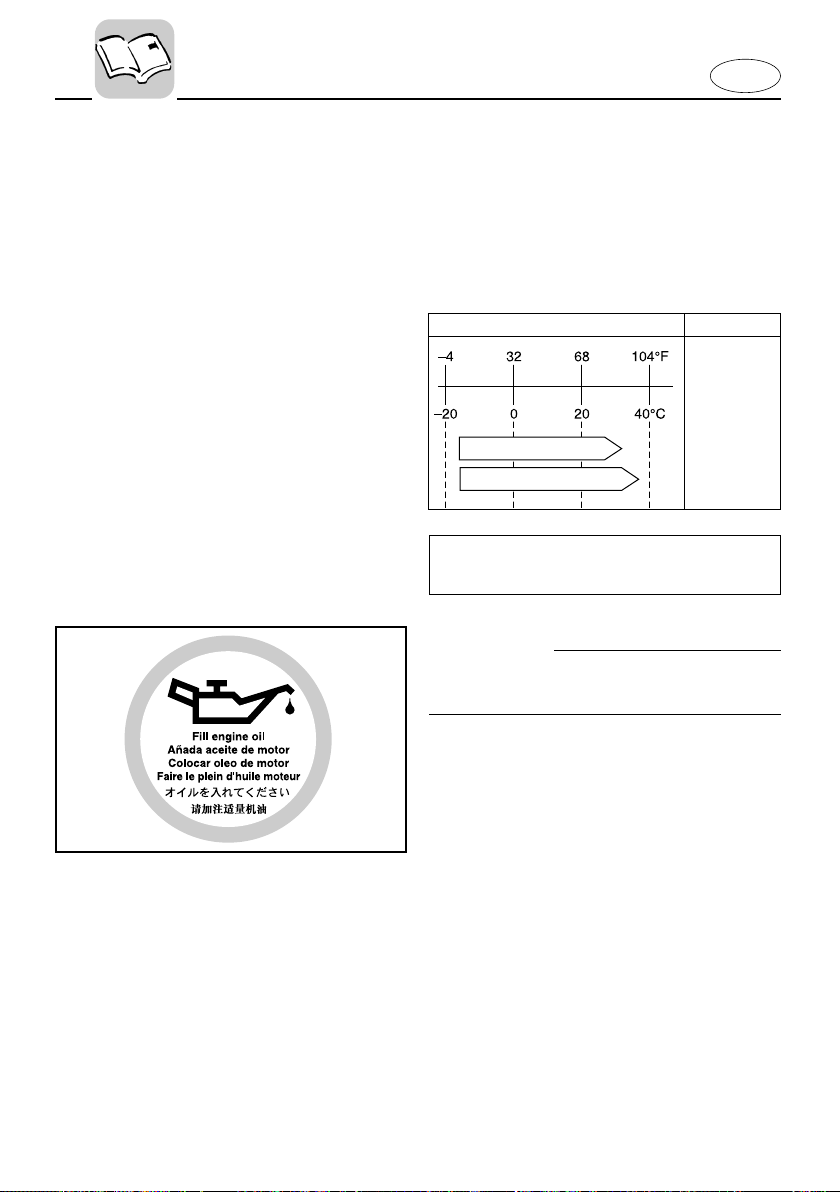
Recommended engine oil:
4-stroke motor oil with a combination of
corresponding SAE and API as shown in
the chart.
SAE API
SE
SF
SG
SH
10W-30
10W-40
SJ
Engine oil quantity:
See Chapter 4, “Specifications.”
cC
All 4-stroke engines are shipped from the
factory without engine oil.
001162
1-13
Page 21
E
EMU01775
BATTERY REQUIREMENT
cC
Do not use a battery that does not meet
the specified capacity. If a battery which
does not meet specifications is used, the
electric system could perform poorly or
be overloaded, causing electric system
damage.
For electric start models, choose a battery
which meets the following specifications.
EMU01859
Minimum cold cranking amps
(CCA/SAE):
245 amps at -18°C (-0.4°F)
Minimum marine cranking amps
(MCA/ABYC):
323 amps at 0°C (32°F)
Minimum reserve capacity (RC/SAE):
52 minutes
EMU01783¯
cC
A battery cannot be connected to models
that do not have a rectifier or Rectifier
Regulator.
Models without a rectifier or Rectifier
Regulator: F25MH
8 If you wish to use a battery with the
above models, install an optional Rectifier Regulator.
1-14
Page 22
602016
10-3/4x17-F
123
12-1/4 x 9 - G
w
eq
E
EMU01395
PROPELLER SELECTION
The performance of your outboard motor
will be critically affected by your choice of
propeller, as an incorrect choice could
adversely affect performance and could
also seriously damage the motor. Engine
speed depends on the propeller size and
boat load. If engine speed is too high or
too low for good engine performance,
this will have an adverse effect on the
engine.
Yamaha outboard motors are fitted with
propellers chosen to perform well over a
range of applications, but there may be
uses where a propeller with a different
pitch would be more appropriate. For a
greater operating load, a smaller-pitch
propeller is more suitable as it enables
the correct engine speed to be maintained. Conversely, a larger-pitch propeller is more suitable for a smaller operating load.
000601
Yamaha dealers stock a range of propellers, and can advise you and install a
propeller on your outboard that is best
suited to your application.
NOTE:
At full throttle and under a maximum
boat load, the engine’s rpm should be
within the upper half of the full throttle
operating range, as listed in “SPECIFICATIONS” on page 4-1. Select a propeller
which fulfills this requirement.
If operating under conditions which allow
the engine’s rpm to rise above the maximum recommended range (such as light
boat loads), reduce the throttle setting to
maintain the rpm in the proper operating
range.
1-15
Page 23

E
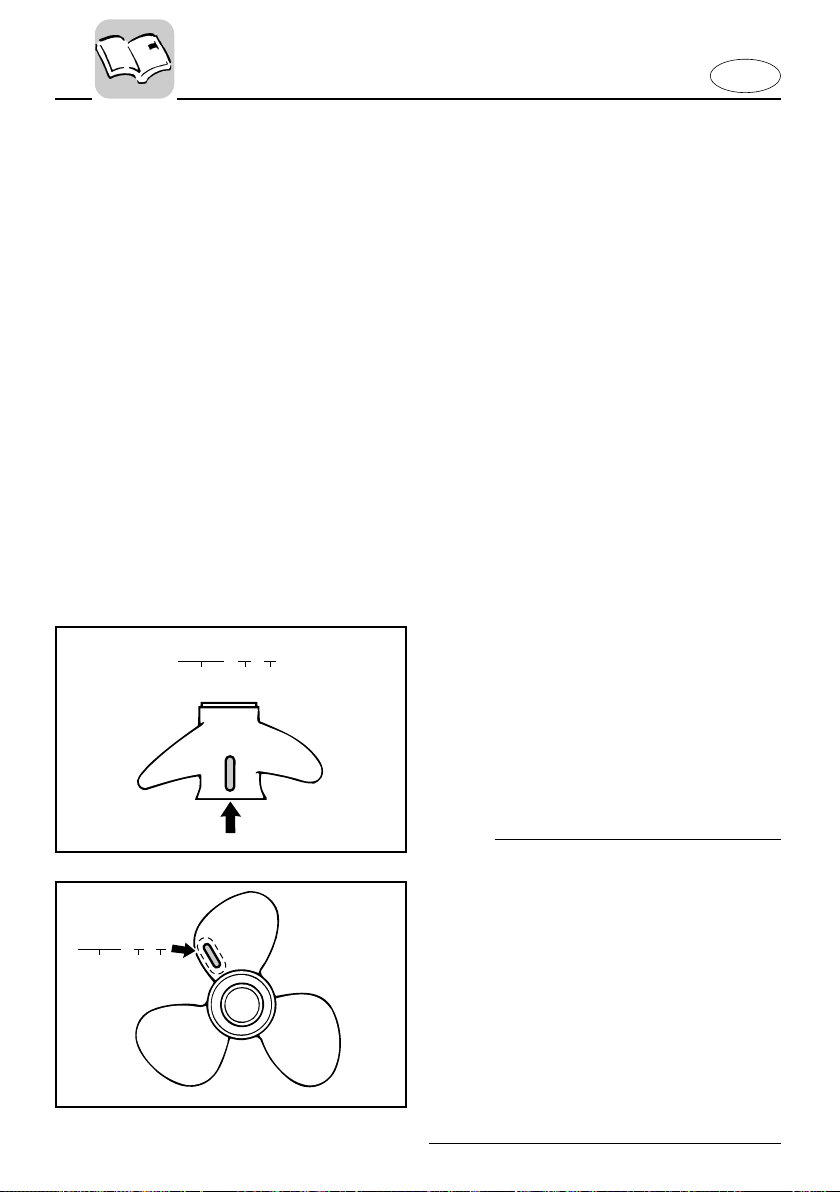
1 Propeller diameter (in inches)
2 Propeller pitch (in inches)
3 Type of propeller (propeller mark)
Refer to the section “CHECKING PROPELLER” for instructions on propeller
removal and installation.
EMU01209
START-IN-GEAR PROTECTION
Yamaha outboard motors or Yamaha
approved remote control units are
equipped with start-in-gear protection
device(s). This feature permits the engine
to be started only when it is Neutral.
Always select Neutral before starting the
engine.
1-16
Page 24

-MEMO-
E
Page 25
E
EMU00037
Chapter 2
BASIC COMPONENTS
MAIN COMPONENTS..............................2-1
OPERATIONS OF CONTROLS AND
OTHER FUNCTIONS ................................2-2
Fuel tank.................................................2-2
Gear shift lever ......................................2-3
Recoil starter handle.............................2-3
Starter button ........................................2-3
Tiller handle...........................................2-3
Remote control......................................2-6
Steering friction adjusting lever........2-10
Trim tab................................................2-11
Trim angle adjusting rod....................2-13
Power trim/tilt switch..........................2-13
Warning indicator(s) ...........................2-14
Digital tachomoter ..............................2-14
Tilt lock mechanism............................2-17
Tilt support knob.................................2-17
Tilt support bar....................................2-17
Top cowling lock lever .......................2-17
Flushing device ...................................2-18
WARNING SYSTEM ..............................2-19
Overheat warning ...............................2-19
Low oil pressure warning ..................2-20
1
2
3
4
5
6
Page 26
!1
!2
!3
!4
!5
!9
!7
!8
!6
@0
@1
q
w
e
r
t
o
i
!0
u
y
@2
@3
@4
EMU01206
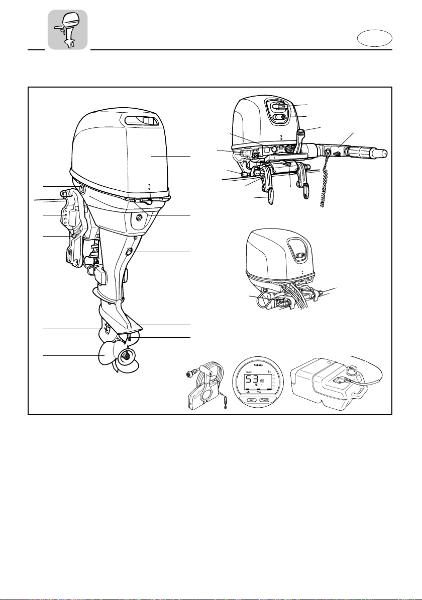
MAIN COMPONENTS
E
1 Top cowling
2 Top cowling lock lever
3 Oil drain bolt
4 Anti-cavitation plate
5 Trim tab
6 Propeller
7 Cooling water inlet
8 Trim angle adjusting rod
9 Clamp bracket
* 0 Power trim and tilt switch
* q Starter button
* w Recoil starter handle
* e Warning indicator
* r Gear shift lever
* t Tiller handle
* y Steering friction adjusting lever
* u Clamp screw
* i Rope attachment
* o Tilt lock lever
p Flushing device
* a Tilt support knob
* s Remote control box
* d Digital tachometer
* f Fuel tank
* May not be exactly as shown; also may not
2-1
be included as standard equipment on all
models.
Page 27
E
q
w
r
902051
e
EMU00039
OPERATIONS OF CONTROLS
AND
OTHER FUNCTIONS
EMU00040
FUEL TANK
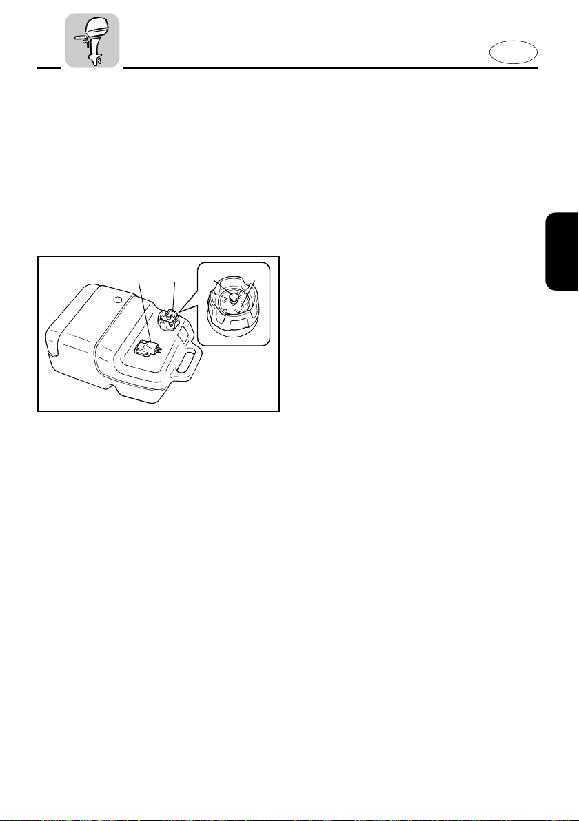
If your model was equipped with a
portable fuel tank, its function is as follows.
1 Fuel hose joint
2 Fuel meter (If equipped)
3 Fuel tank cap
4 Air vent screw (If equipped)
EMU00042
Fuel Hose Joint
This connector is provided for connecting
or disconnecting fuel hose.
EMU00044
Fuel Meter
This meter is on the fuel tank cap. It
shows current fuel quantity in the fuel
tank approximately.
EMU00045
Fuel Tank Cap
This cap is for filling fuel. To remove it,
turn it counterclockwise.
EMU00046
Air Vent Screw
This screw is on the fuel tank cap. To
loosen it, turn it counterclockwise.
2-2
Page 28
E
101043**
e
q
w
EMU00051
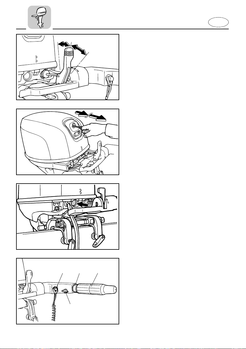
GEAR SHIFT LEVER
(for Tiller control model)
Turning the gear-shift lever towards you
engages the clutch with the forward gear
so that the boat moves ahead. Turning
the lever away from you engages the
reverse gear so that the boat moves
astern.
1 Neutral
2 Forward
3 Reverse
EMU00059
RECOIL STARTER HANDLE
(If equipped)
Pull the handle gently until resistance is
felt. Then vigorously pull the handle
straight out to crank the engine to start it.
EMU00060
STARTER BUTTON
(for Tiller control model)
When you push the starter button, the
electric starter motor cranks the engine to
start it.
r
e
EMU00064
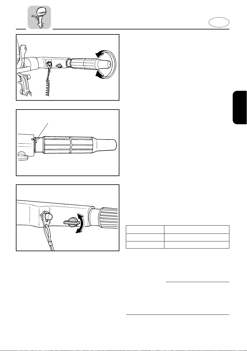
TILLER HANDLE
(for Tiller control model)
qw
Moving the tiller handle sideways to
adjust the steering direction. In addition,
this handle contains the functions as follows.
1 Throttle control grip
2 Throttle indicator
3 Throttle friction adjusting knob/screw
4 Engine stop button / Engine stop lanyard
switch
2-3
Page 29
E
502016
EMU00065
Throttle Control Grip
The throttle control grip is on the tiller
handle. Turn the grip counterclockwise to
increase speed and clockwise to decrease
speed.
EMU00067
q
START
Throttle Indicator
The fuel consumption curve on the throttle indicator shows the relative amount of
fuel consumed for each throttle position.
Choose the setting that offers the best
performance and fuel economy for the
desired operation.
1 Throttle indicator
EMU01294
Throttle Friction Adjusting Knob
A friction device in the tiller handle provides resistance to movement of the
throttle grip. This is adjustable for operator preference.
Resistance Knob
Increase Turn clockwise
Decrease Turn counterclockwise
When constant speed is desired, tighten
the adjusting knob to maintain the
desired throttle setting.
w
Do not overtighten the friction adjusting
knob. If there is too much resistance, it
may be difficult to move the throttle grip,
which could result in an accident.
2-4
Page 30
E
q
w
000647
EMU00932
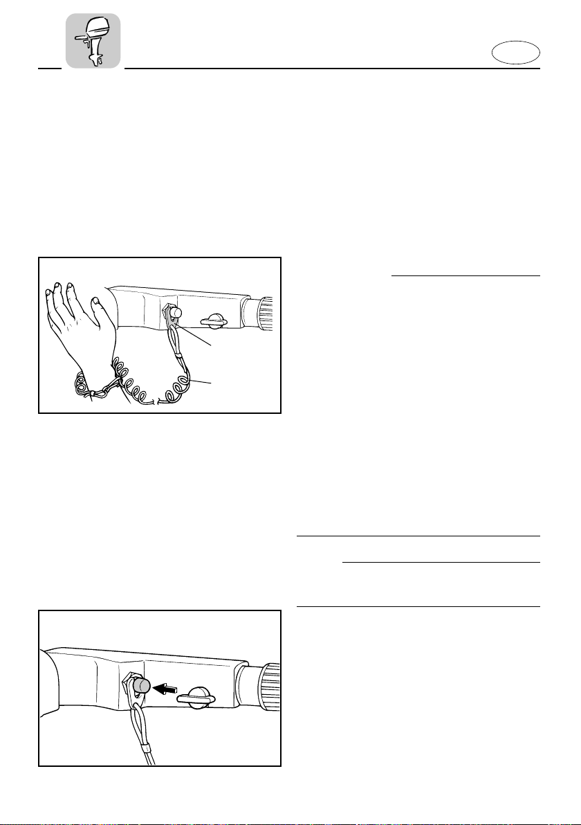
Engine Stop Lanyard Switch
The lock-plate 1 must be attached to the
engine stop lanyard switch for the engine
to run. The lanyard 2 should be attached
to a secure place on the operator’s clothing, or arm or leg. Should the operator fall
overboard or leave the helm, the lanyard
will pull out the lock plate, stopping ignition to the engine. This will prevent the
boat from running away under power.
w
8 Attach the lanyard to a secure place on
your clothing, your arm or leg while
operating.
8 Do not attach the lanyard to clothing
that could tear loose. Do not route the
lanyard in such a way that it could
become entangled, preventing it from
functioning.
8 Avoid accidentally pulling the lanyard
during normal operation. Loss of
engine power means the loss of most
steering control. Also, without engine
power, the boat could slow rapidly.
This could cause people and objects in
the boat to be thrown forward.
NOTE:
The engine cannot be started with the
lock-plate removed.
EMU00072
Engine Stop Button
Pushing this button opens the ignition circuit and stops the engine.
506021
2-5
Page 31
E
000200
w
q
e
r
t
y
u
R
N
F
q
w
e
r
t
y
u
u
t
r
y
701031
701036
EMU00096*
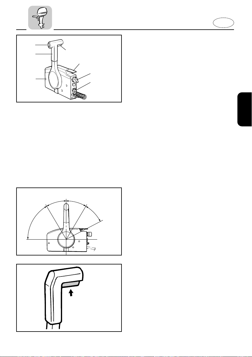
REMOTE CONTROL
Both the shifter and the throttle are actuated by the remote control lever.
Additionally, the remote control also has
the electrical switches.
1 Remote control lever
2 Neutral interlock trigger
3 Neutral throttle lever
4 Main switch
5 Engine stop lanyard switch
6 Power trim and tilt switch (if equipped)
7 Throttle friction adjusting screw
EMU00098*
Remote Control Lever
Moving the lever forward from the
Neutral position engages Forward gear.
Pulling the lever back from Neutral
engages Reverse. The engine will continue to run at idle until the lever is moved
about 35° (a detent can be felt). Moving
the lever further opens the throttle, and
the engine will begin to accelerate.
1 Neutral
2 Forward
3 Reverse
4 Shift
5 Fully closed
6 Throttle
7 Fully open
EMU00099
Neutral Interlock Trigger
To shift out of Neutral, the neutral interlock trigger of the remote control lever
must first be pulled up.
2-6
Page 32
N
701033*
q
w
ON
E
EMU00100
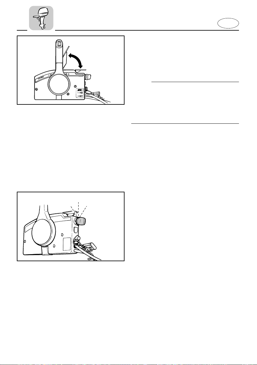
Neutral Throttle Lever
To open the throttle without shifting into
either Forward or Reverse, place the
remote control lever in the Neutral position and lift the neutral throttle lever.
NOTE:
The neutral throttle lever will operate only
when the remote control lever is in
Neutral. The remote control lever will
operate only when the neutral throttle
lever is in the closed position.
1 Fully open
2 Fully closed
EMU00101
STARTOFF
701021
Main switch
The main switch controls the ignition system; its operation is described below.
8 OFF
Electrical circuits switched off.
(The key can be removed.)
8 ON
Electrical circuits switched on.
(The key cannot be removed.)
8 START
Starter-motor will turn and start engine.
(When the key is released, it returns automatically to “ON”.)
2-7
Page 33
E
000569
q
w
EMU00934
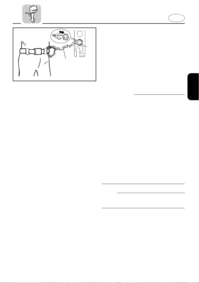
Engine Stop Lanyard Switch
The lock-plate 1 must be attached to the
engine stop lanyard switch for the engine
to run. The lanyard 2 should be attached
to a secure place on the operator’s clothing, or arm or leg. Should the operator fall
overboard or leave the helm, the lanyard
will pull out the lock plate, stopping ignition to the engine. This will prevent the
boat from running away under power.
w
8 Attach the lanyard to a secure place on
your clothing, your arm or leg while
operating.
8 Do not attach the lanyard to clothing
that could tear loose. Do not route the
lanyard in such a way that it could
become entangled, preventing it from
functioning.
8 Avoid accidentally pulling the lanyard
during normal operation. Loss of
engine power means the loss of most
steering control. Also, without engine
power, the boat could slow rapidly.
This could cause people and objects in
the boat to be thrown forward.
NOTE:
The engine cannot be started with the
lock-plate removed.
2-8
Page 34
E
UP
DN
701034*
UP
DN
EMU01331
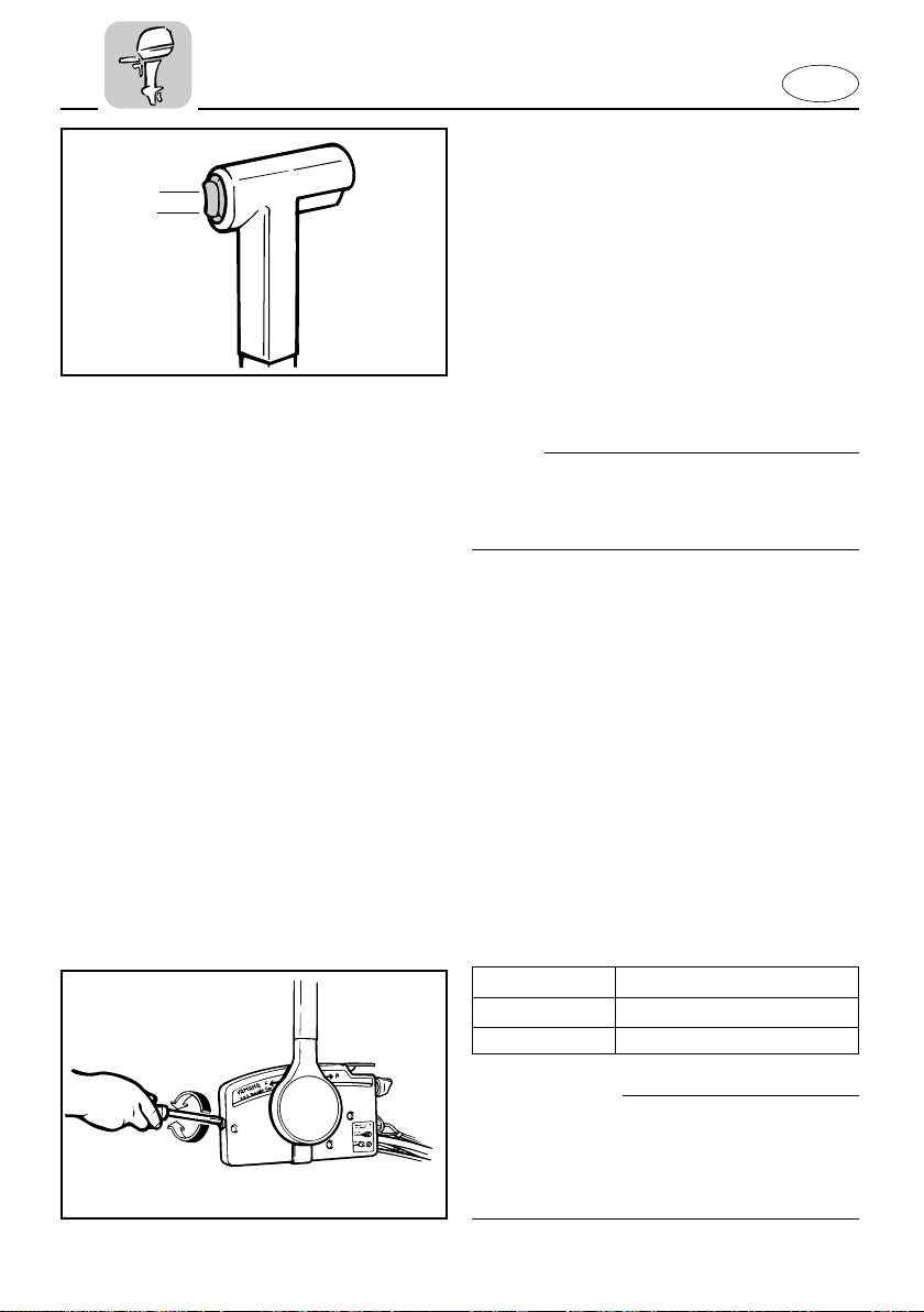
Power Trim/Tilt Switch
The power trim/tilt adjusts the motor
angle in relation to the transom. The
power trim/tilt switch is located on the
remote control lever grip. Pushing the
switch “UP” trims the motor up, then tilts
the motor up. Pressing the switch “DN”
tilts the motor down and trims the motor
down. When the switch button is
released, the motor will stop in its current
position.
NOTE:
Refer to the sections “ADJUSTING TRIM
ANGLE” and “TILTING UP/DOWN” in
Chapter 3 for instructions on usage.
EMU01155
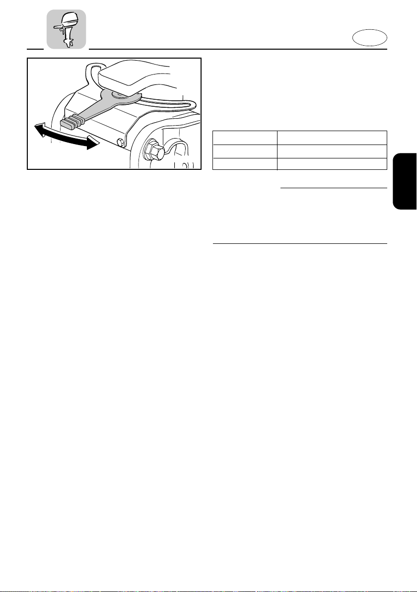
Throttle Friction Adjusting Screw
A friction device in the remote control box
provides adjustable resistance to movement of the remote control lever, and can
be set according to operator preference.
An adjusting screw is located on the front
of the remote control box.
Resistance Screw
Increase Turn clockwise
Decrease Turn counterclockwise
w
701035
Do not overtighten the friction adjusting
screw. If there is too much resistance, it
may be difficult to move the lever, which
could result in an accident.
2-9
Page 35
E
408026
EMU00110*
STEERING FRICTION ADJUSTING
LEVER
A friction device provides resesistance
steering movement. This is adjustable for
operator preference.
Resistance Lever
Increase Turn clockwise
Decrease Turn counterclockwise
w
Do not overtighten the friction adjusting
lever. If there is too much resistance, it
may be difficult to steer, which could
result in an accident.
2-10
Page 36
E
q
w
603013*
A
B
EMU00114
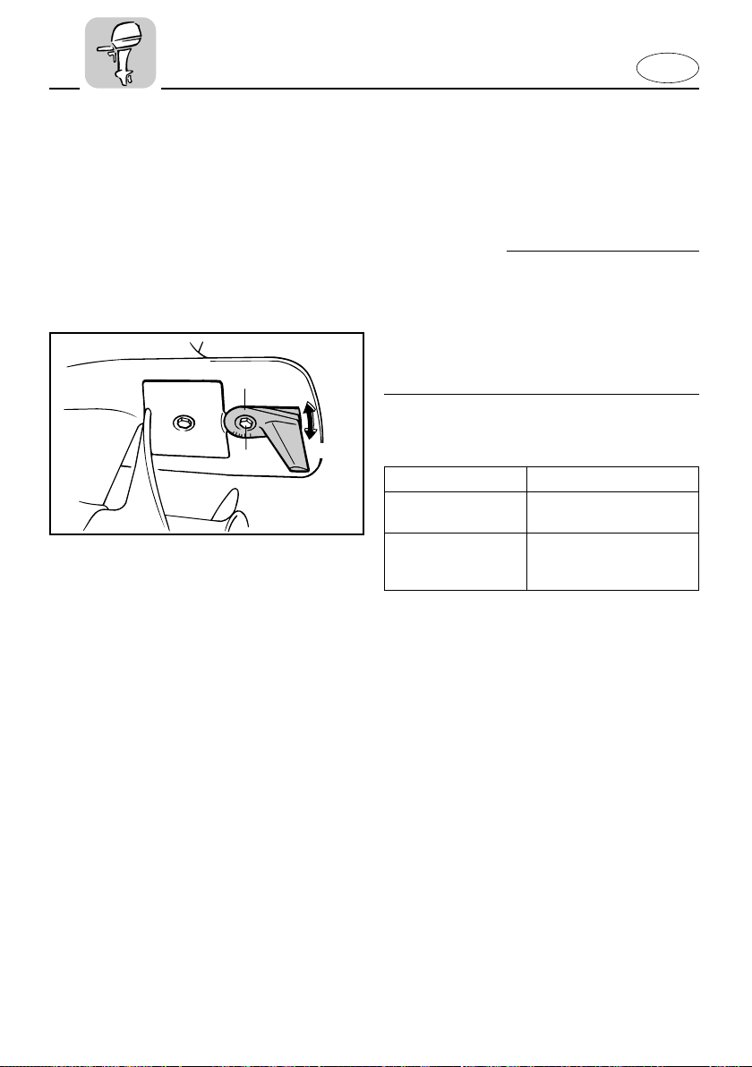
TRIM TAB
The trim tab should be adjusted so that
the steering control can be turned to
either the right or left by applying the
same amount of force.
w
An improperly adjusted trim tab may
cause difficult steering. Always test run
after the trim tab has been installed or
replaced to be sure steering is correct. Be
sure you have tightened the bolt after
adjusting the trim tab.
1 Trim tab
2 Bolt
Boat tends to veer
To the left
(port side)
To the right
(starboard side)
The fin of trim tab
“Turn to the left(port
side), “A” in the figure”
“Turn to the right(starboard side), “B” in the
figure”
2-11
Page 37
603021
q
w
A
B
FT25
E
EMU00113*
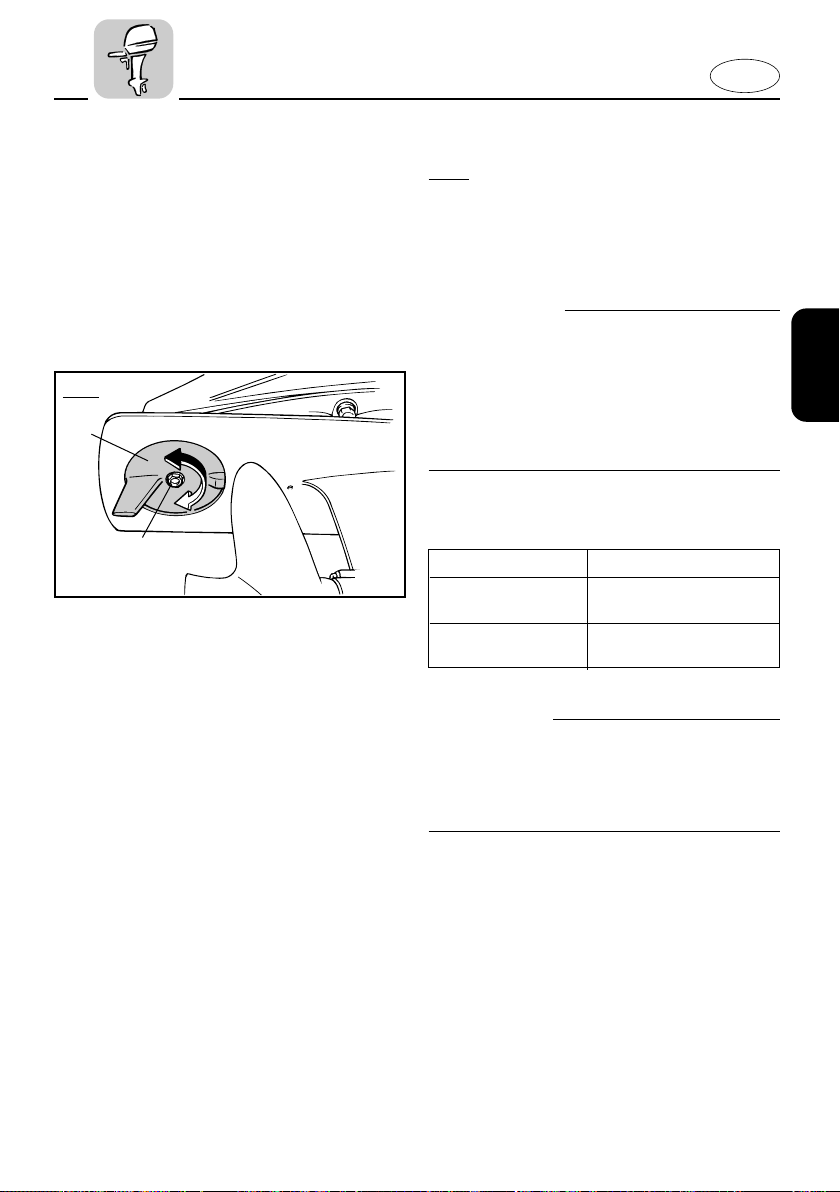
TRIM TAB
FT25
The trim tab should be adjusted so that
the steering control can be turned to
either the right or left by applying the
same amount of force.
w
An improperly adjusted trim tab may
cause difficult steering. Always test run
after the trim tab has been installed or
replaced to be sure steering is correct. Be
sure you have tightened the bolt after
adjusting the trim tab.
1 Trim tab
2 Bolt
Boat tends to veer
To the left
(port side)
To the right
(starboard side)
The fin of trim tab
Turn to the left
(A in the figure)
Turn to the right
(B in the figure)
cC
The trim tab also serves as an anode to
protect the engine from electrochemical
corrosion. Never paint the trim tab as it
will become ineffective as an anode.
2-12
Page 38
302014*
UP
DN
404012
E
EMU01297
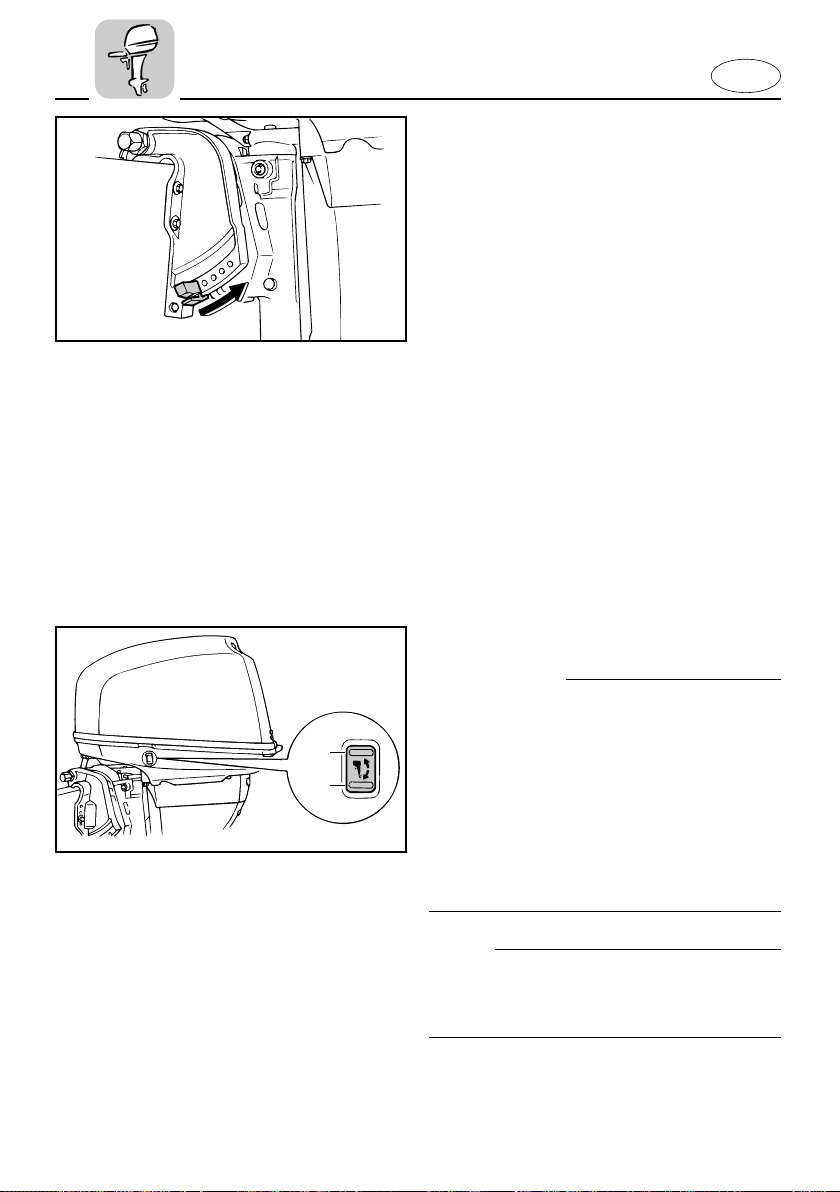
TRIM ANGLE ADJUSTING ROD
The position of the trim angle adjusting
rod determines the minimum trim angle
of the outboard motor in relation to the
transom.
EMU01125
POWER TRIM/TILT SWITCH
The power trim/tilt adjusts the motor
angle in relation to the transom. The
power trim/tilt switch is located on the
side of the bottom engine cowling.
Pushing the switch “UP” trims the motor
up, then tilts the motor up. Pressing the
switch “DN” tilts the motor down and
trims the motor down. When the switch
button is released, the motor will stop in
its current position.
w
Use the power trim/tilt switch located on
the bottom engine cowling only when
the boat is at a complete stop with the
engine off. Attempting to use the cowling-mounted power trim/tilt switch while
the boat is moving could increase the risk
of falling overboard and could distract
the operator, increasing the risk of collision with another boat or an obstacle.
NOTE:
Refer to the section “Adjusting Trim
Angle” and “Tilting Up/Down” for instructions on usage.
2-13
Page 39
223012
q
e
q
w
E
EMU01128
WARNING INDICATOR(S)
If the engine develops a condition monitored by the warning system, an indicator
will come on.
Refer to the “WARNING SYSTEM” section for details.
1 Warning indicator(s)
EMU01617
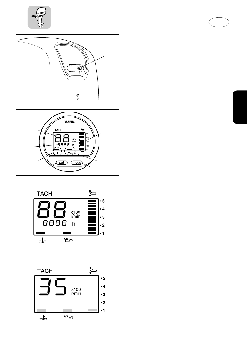
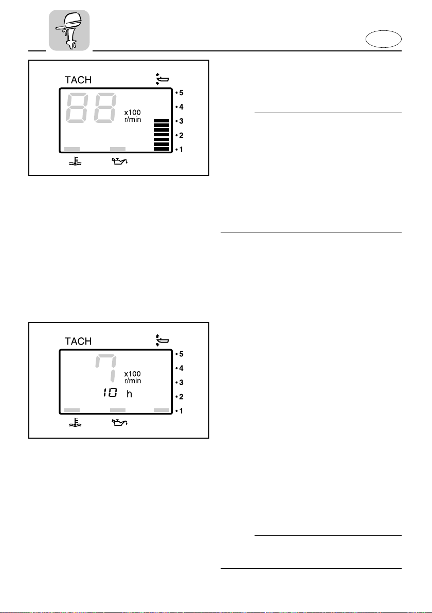
DIGITAL TACHOMETER
This gauge contains the tachometer, trim
meter, hour meter, low oil pressure warning indicator, and the overheat warning
indicator.
t
y
u
r
001081
001085
001058
1 Tachometer
2 Trim meter
3 Hour meter
4 Low oil pressure warning indicator
5 Overheat warning indicator
6 Set button
7 Mode button
NOTE:
All segments of the display will light
momentarily after the main switch is
turned on and will return to normal thereafter.
EMU00136
Tachometer
This meter shows the engine speed.
2-14
Page 40
001059
001088
E
EMU01109
Trim Meter
This meter shows the trim angle of your
outboard motor.
NOTE:
8 Memorize the trim angles that work
best for your boat under different condi-
tions. Adjust the trim angle to the
desired setting by operating the power
trim and tilt switch.
8 If the trim angle of your motor exceeds
the trim operating range, the top seg-
ment on the trim meter display will start
to blink.
EMU01620
Hour Meter
This meter shows the number of hours
the engine has been run. It can be set to
show the total number of hours or the
number of hours for the current trip. The
display can also be turned on and off.
8 Changing the display format
Pressing the MODE button changes the
display format in the following circular
pattern:
Total hours - Trip hours - Display off
8 Resetting the trip hours
Simultaneously pressing the SET and
MODE buttons for more than 1 second
while the trip hours are displayed resets
the trip counter to 0 (zero).
NOTE:
The total number of hours the engine has
been run cannot be reset.
2-15
Page 41
001060
q
q
E
EMU01110
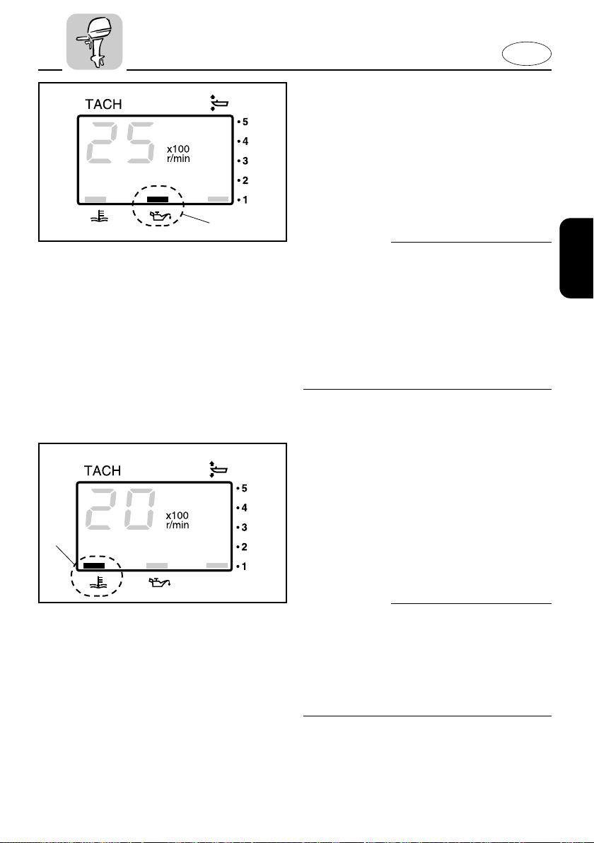
Low Oil Pressure Warning Indicator
If oil pressure drops too low, the warning
indicator will start to blink. Refer to the
section “LOW OIL PRESSURE WARNING”
for details.
1 Low oil pressure warning indicator
cC
8 Do not operate the engine without oil.
Serious engine damage will occur.
8 The low oil pressure warning indicator
does not indicate the oil level in the
engine. Use the Oil Level Gauge to
check the remaining oil quantity. (Refer
to the section “CHECKING THE ENGINE
OIL LEVEL” for details.)
EMU01553
Overheat Warning Indicator
If the engine temperature rises too high,
the warning indicator will start to blink.
Refer to “OVERHEAT WARNING” for
details.
1 Overheat warning indicator
001061
cC
Do not continue to operate the engine if a
warning device has activated. If necessary, refer to the “TROUBLESHOOTING”
section in this manual. Consult your dealer if the problem cannot be located and
corrected.
2-16
Page 42
301044
q
403052
q
402073
q
403054
E
EMU00153
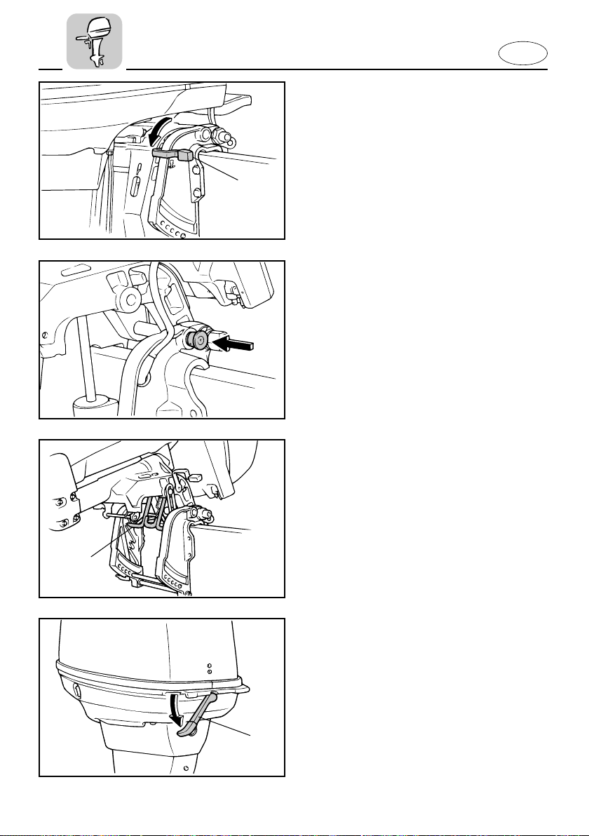
TILT LOCK MECHANISM
(for Manual tilt model)
The tilt-lock mechanism is used to prevent reverse thrust from the propeller lifting the outboard motor when reversing.
To lock it, set the tilt-lock lever in the Lock
position.
To release it, place the tilt-lock lever in the
Tilt position.
1 Tilt-lock lever
EMU00155
TILT SUPPORT KNOB
To keep the outboard motor in the tiltedup position, push the tilt support knob
under the swivel bracket.
EMU00156
TILT SUPPORT BAR
The tilt support bar 1 keeps the outboard
motor in the tilted up position.
EMU00162
TOP COWLING LOCK LEVER
To remove the engine top cowling, turn
the lock lever. Then lift off the cowling.
When replacing the cowling, check to be
sure it fits properly in the rubber seal.
Then lock the cowling again by moving
the lever upward.
1 Top cowling lock lever
2-17
Page 43
q
101043*
E
EMU01146
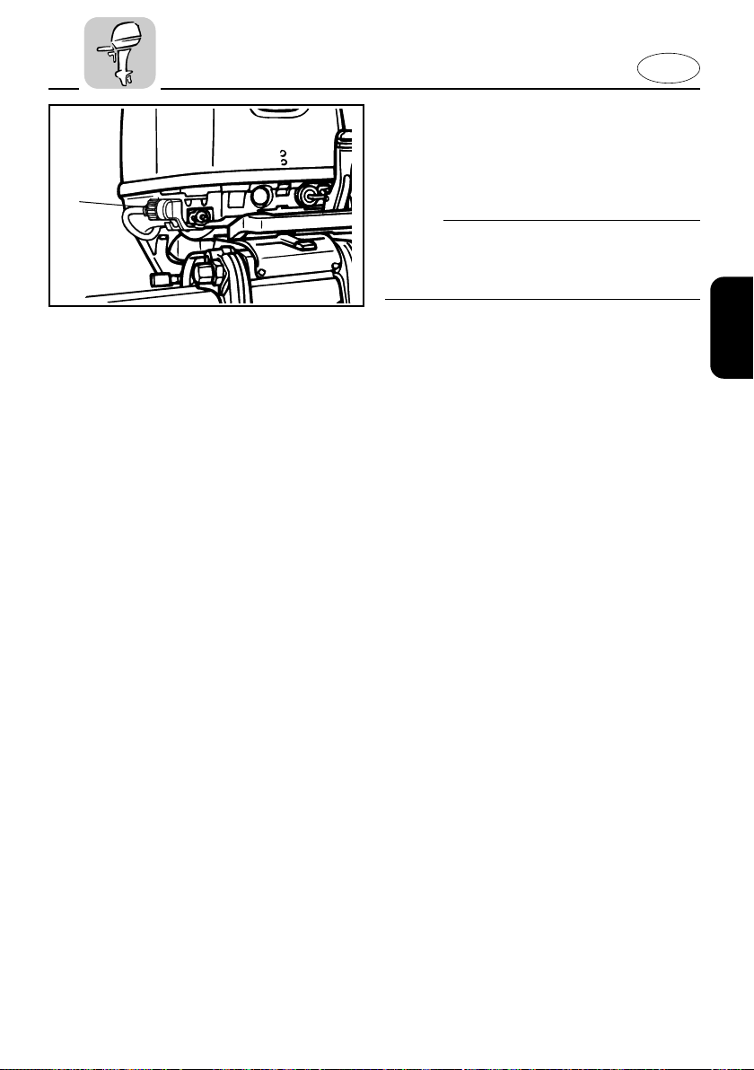
FLUSHING DEVICE
This device 1 is used to clean the cooling
water passages of the motor using a garden hose and tap water.
NOTE:
Refer to “Cleaning Cooling-water
Passages” in Chapter 4 for instructions on
usage.
2-18
Page 44
E
701054
001053
EMU00169
WARNING SYSTEM
cC
Do not continue to operate the engine if
the warning device has activated. Consult
your Yamaha dealer if the problem cannot be located and corrected.
EMU01476
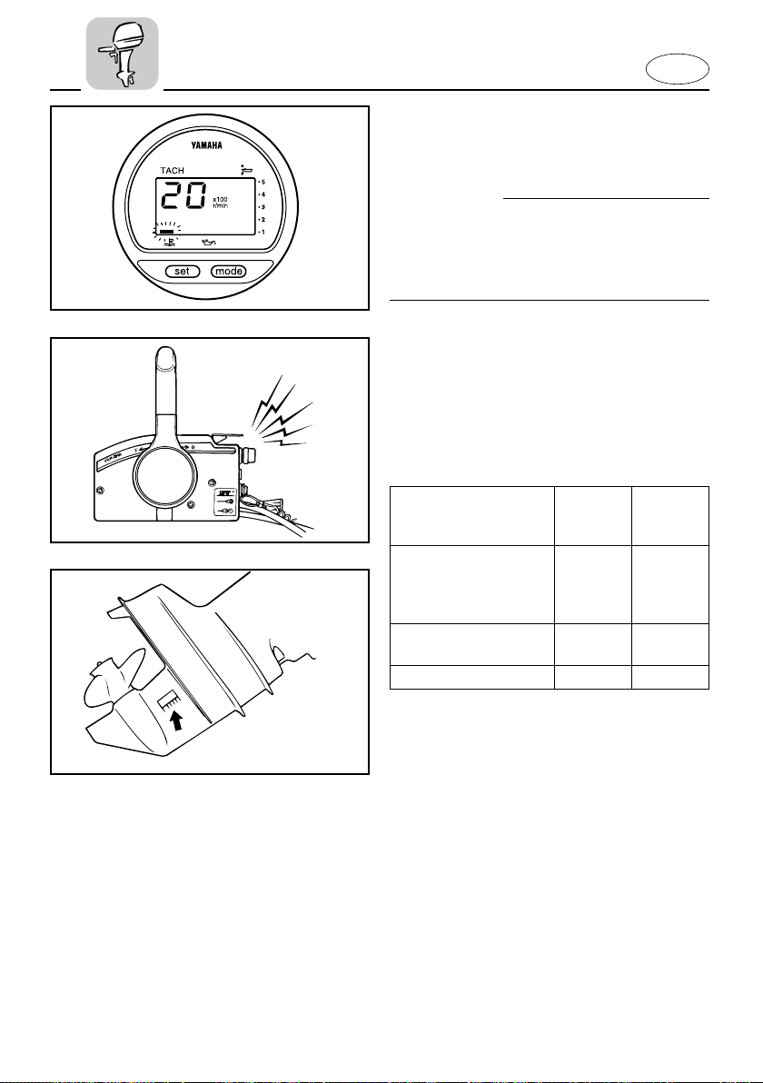
OVERHEAT WARNING
This engine has an overheat warning
device. If the engine temperature rises too
high, the warning device will activate.
(
1) ; Included (–); N/A
Activation of
warning device
The engine speed
will automatically
decrease to about
2,000 r/min.
The overheat warning
indicator will come on.
The buzzer will sound.
Tiller Remote
control control
model model
11
— 1
— 1
*
605021
If the warning system has been activated,
stop the engine and check the water inlet
for clogging.
* Not equipped on all models.
2-19
Page 45
E
223012**
001063
F25MH/F25EH
EMU00173
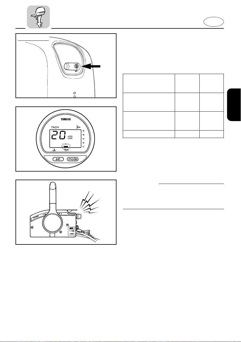
LOW OIL PRESSURE WARNING
If oil pressure drops too low, the warning
device will activate.
(1):Included (–):N/A
Activation of warning
device
Engine speed will
automatically decrease
to about 2,000 r/min.
The low oil pressure
warning indicator will
come on.
The buzzer will sound.
Tiller Remote
control control
model model
11
11
— 1
If the warning system has been activated,
stop the engine as soon as it is safe to do
so. Check oil level and add oil as needed.
If the oil level is correct, consult your
Yamaha dealer.
cC
Do not continue to run the engine if the
low oil pressure lamp is “ON”. Serious
engine damage may occur.
701054
2-20
Page 46

-MEMO-
E
Page 47
E
EMU00174
Chapter 3
OPERATION
INSTALLATION ........................................3-1
Mounting the outboard motor ............3-2
Clamping the outboard motor.............3-4
BREAKING IN (RUNNING IN) ENGINE ..3-5
PRE-OPERATION CHECKS ......................3-6
Checking the engine oil level...............3-7
FILLING FUEL ...........................................3-8
STARTING ENGINE .................................3-9
WARMING UP ENGINE .........................3-14
1
2
3
SHIFTING ................................................3-15
Forward................................................3-15
Reverse ................................................3-16
STOPPING ENGINE ...............................3-17
TRIMMING OUTBOARD MOTOR.........3-18
Adjuting trim angle.............................3-19
TILTING UP/DOWN ...............................3-22
CRUISING IN SHALLOW WATER.........3-25
CRUISING IN OTHER CONDITIONS.....3-27
Cruising in salt water..........................3-27
Cruising in turbid water .....................3-27
4
5
6
Page 48

E
EMU00175
INSTALLATION
cC
Incorrect engine height or obstructions to
smooth water flow (such as the design or
condition of the boat or accessories such
as transom ladders/depth finder transducers) can create airborne water spray
while the boat is cruising. Severe engine
damage may result if the motor is operated continuously in the presence of airborne water spray.
NOTE:
During water testing check the buoyancy
of the boat, at rest, with its maximum
load. Check that the static water level on
the exhaust housing is low enough to prevent water entry into the powerhead,
when water rises due to waves when the
outboard is not running.
3-1
Page 49
E
104011
q
EMU00176
MOUNTING THE OUTBOARD
MOTOR
w
Improper mounting of the outboard
motor could result in hazardous conditions such as poor handling, loss of control, or fire hazards. Observe the following:
8 The information presented in this sec-
tion is intended as reference only. It is
not possible to provide complete
instructions for every possible
boat/motor combination. Proper
mounting depends in part on experi-
ence and the specific boat/motor com-
bination.
8 Your dealer or other person experi-
enced in proper rigging should mount
the motor. If you are mounting the
motor yourself, you should be trained
by an experienced person. [permanent
mounted type]
8 Your dealer or other person experi-
enced in proper outboard motor
mounting should show you how to
mount your motor. [portable type]
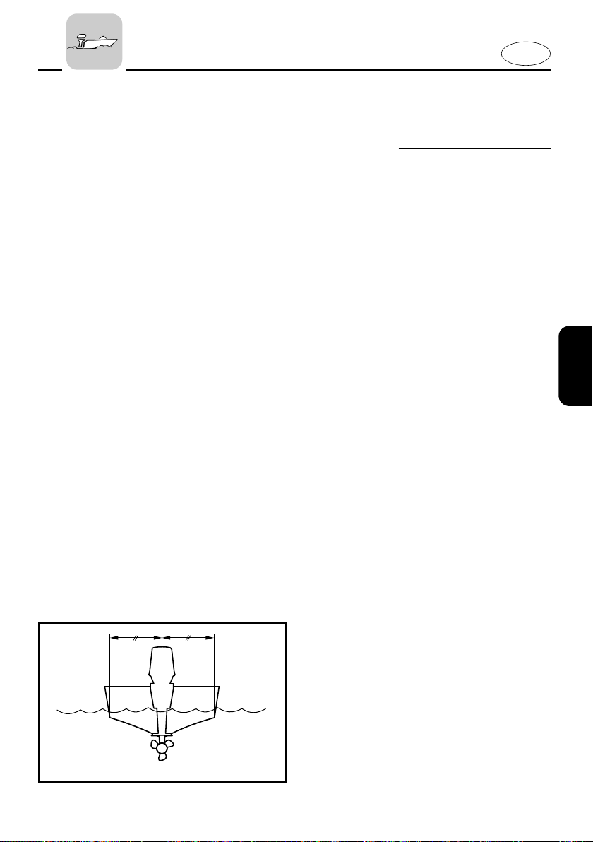
Mount the outboard motor on the center
line (keel line) of the boat, and ensure that
the boat itself is well balanced. Otherwise,
the boat will be hard to steer. For boats
without a keel or which are asymmetrical,
consult your dealer.
1 Center line (keel line)
3-2
Page 50
E
104013*
0~25mm
(0~1in.)
w
Overpowering a boat may cause severe
instability. Do not install an outboard
motor with more horsepower than the
maximum rating on the capacity plate of
the boat. If the boat does not have a
capacity plate, consult the boat manufacturer.
EMU01298
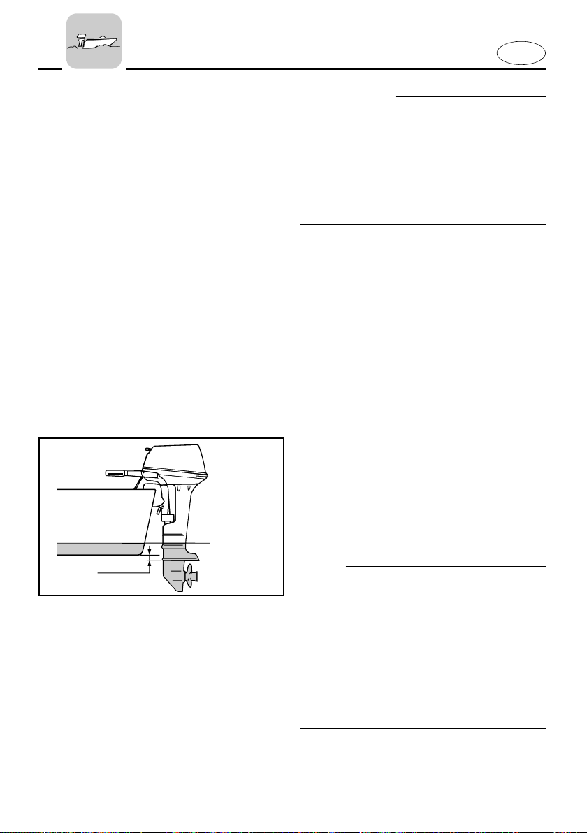
Mounting Height
To run your boat at optimum efficiency,
the water-resistance (drag) of the boat
and outboard motor must be made as little as possible. The mounting-height of
the outboard motor greatly affects the
water-resistance. If the mounting-height
is too high, cavitation tends to occur, thus
reducing the propulsion; and if the propeller tips cut the air, the engine speed
will rise abnormally and cause the engine
to overheat. If the mounting-height is too
low, the water-resistance will increase
and thereby reduce engine efficiency.
Mount the engine so that the anti-cavitation plate is between the bottom of the
boat and a level 25 mm (1 in.) below it.
NOTE:
8 The optimum mounting height of the
outboard motor is affected by the
boat/motor combination and the
desired use. Test runs at different
heights can help determine the opti-
mum mounting height.
8 Refer to the section “TRIMMING OUT-
BOARD MOTOR” for instructions on
setting the trim angle of the outboard.
3-3
Page 51
409011
q
410012
409014
E
EMU01318
CLAMPING THE OUTBOARD MOTOR
Manual tilt model
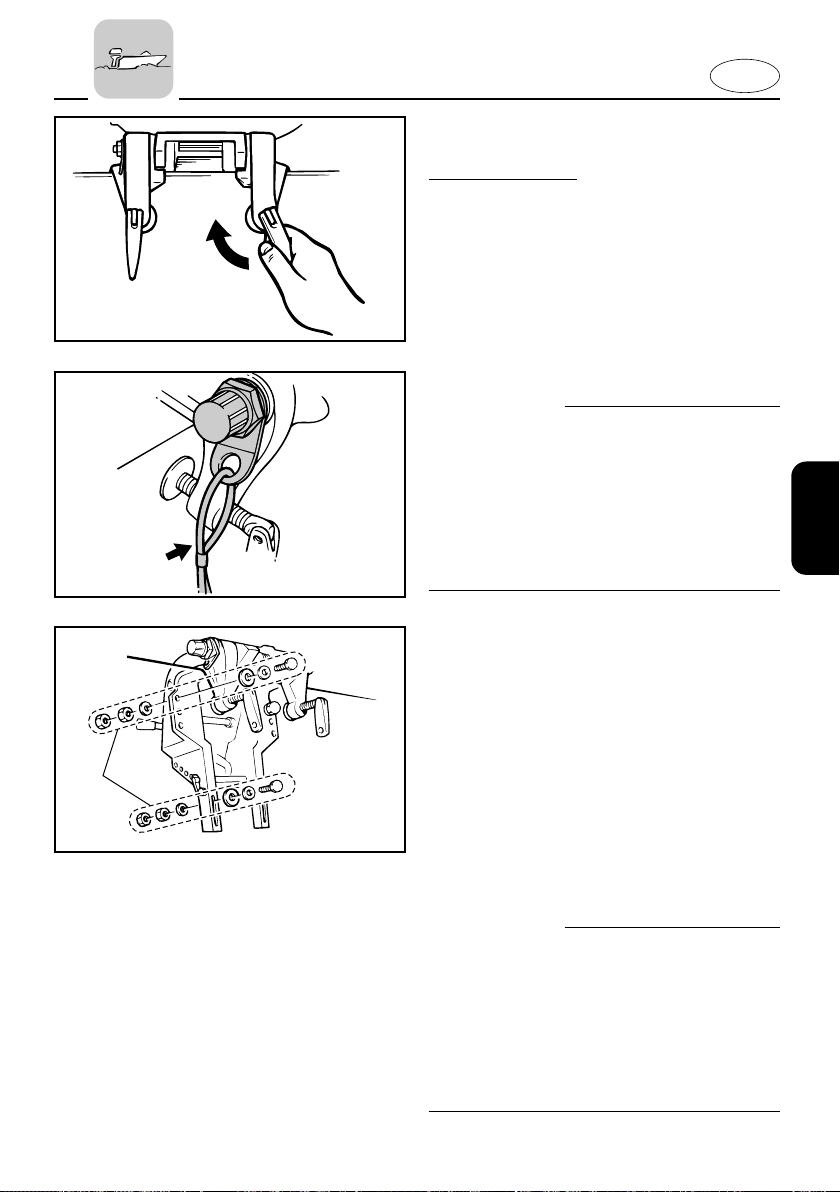
1) Place the outboard on the transom so
that it is positioned as close to the
center as possible. Tighten the transom clamp screws evenly and securely. Check the clamp-screws for tightness occasionally during operation of
the motor as they can work loose due
to engine vibration.
w
Loose clamp screws could allow the
motor to move on the transom or fall off
the transom. This could cause loss of
control and serious injury. Make sure the
transom screws are tightened securely.
Occasionally check the screws for tightness during operation.
2) An engine restraint cable or chain
should be used. Attach one end to
the engine restraint cable attachment
point and the other to a secure
mounting point on the boat.
Otherwise, the engine could be completely lost if it accidentally falls off
the transom.
Secure the clamp bracket to the transom with the bolts provided with the
outboard. For details, consult your
dealer.
w
Avoid using bolts, nuts or washers other
than those contained in the engine packaging. If used, they must be of at least
the same quality of material and strength
and must be tightened securely. After
tightening, test run the engine and check
their tightness.
1 Motor mounting parts
3-4
Page 52

E
EMU00224
BREAKING IN (RUNNING IN)
ENGINE
Your new engine requires a period of
break-in (running-in) to allow mating surfaces of moving parts to wear-in evenly.
Correct break-in (running-in) will help
ensure proper performance and longer
engine life.
cC
Failure to follow the break-in (running-in)
procedure may result in reduced engine
life or even severe engine damage.
Break-in (running-in) time: 10 hours
EMU00233
Run the engine under load (in gear with a
propeller installed) as follows.
1) For the first hour of operation:
Run the engine at 2,000 r/min or at
approximately half throttle.
2) For the second hour of operation:
Run the engine at 3,000 r/min or at
approximately three-quarter throttle,
and during this period run it at full
throttle for approximately one minute
every ten minutes.
3) For the next eight hours of operation:
Avoid continuous operation at full
throttle for more than five minutes at
a time.
4) After these first 10 hours:
Operate the engine normally.
3-5
Page 53
E
EMU00204
PRE-OPERATION CHECKS
w
If any item in the pre-operation check is
not working properly, have it inspected
and repaired before operating the outboard motor. Otherwise, an accident
could occur.
cC
Do not start the engine out of water.
Overheating and serious engine damage
can occur.
EMU00206
Fuel
8 Check to be sure you have plenty of fuel
for your trip.
8 Make sure there are no fuel leaks or
gasoline fumes.
8 Check fuel line connections to be sure
they are tight.
8 Be sure the fuel tank is positioned on a
secure, flat surface, and that the fuel
hose is not twisted or flattened, or likely
to contact sharp objects.
EMU00208
Oil
8 Check the level of the oil in the sump
with the dipstick. If necessary, add oil to
bring the level up to the upper mark.
3-6
Page 54
201015
q
w
e
q
E
EMU00209
Controls
8 Check throttle, shift, and steering for
proper operation before starting the
engine.
8 The controls should work smoothly,
without binding or unusual free play.
8 Look for loose or damaged connec-
tions.
8 Check operation of the starter and stop
switches when the outboard motor is in
the water.
EMU00210
Engine
8 Check the engine and engine mounting.
8 Look for loose or damaged fasteners.
8 Check the propeller for damage.
EMU01436
CHECKING THE ENGINE OIL LEVEL
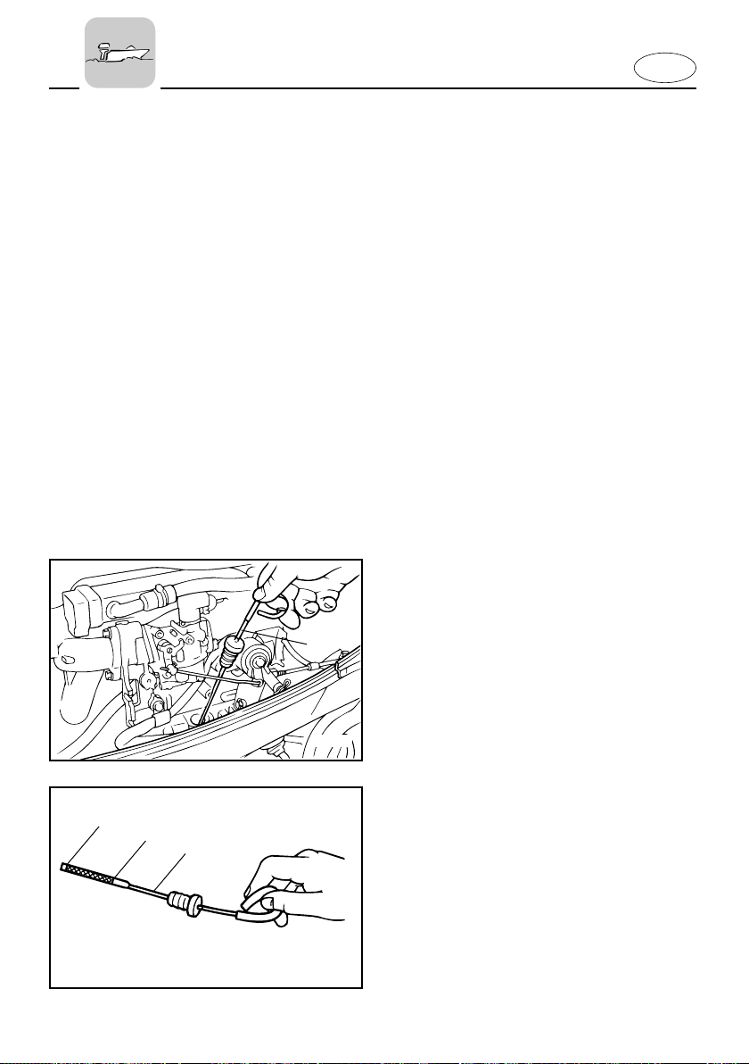
1) Put the outboard motor in an upright
position (not tilted).
2) Pull out the oil dipstick and wipe it
clean.
3) Completely re-insert the dipstick and
pull out it again.
4) Check the oil level using the dipstick
to be sure the level falls between the
upper and lower marks. Fill with oil if
it is below the lower mark, or drain to
the specified level if it is above the
upper mark.
1 Oil dipstick
2 Lower level mark
3 Upper level mark
201012*
3-7
Page 55
E
902055
EMU00202
FILLING FUEL
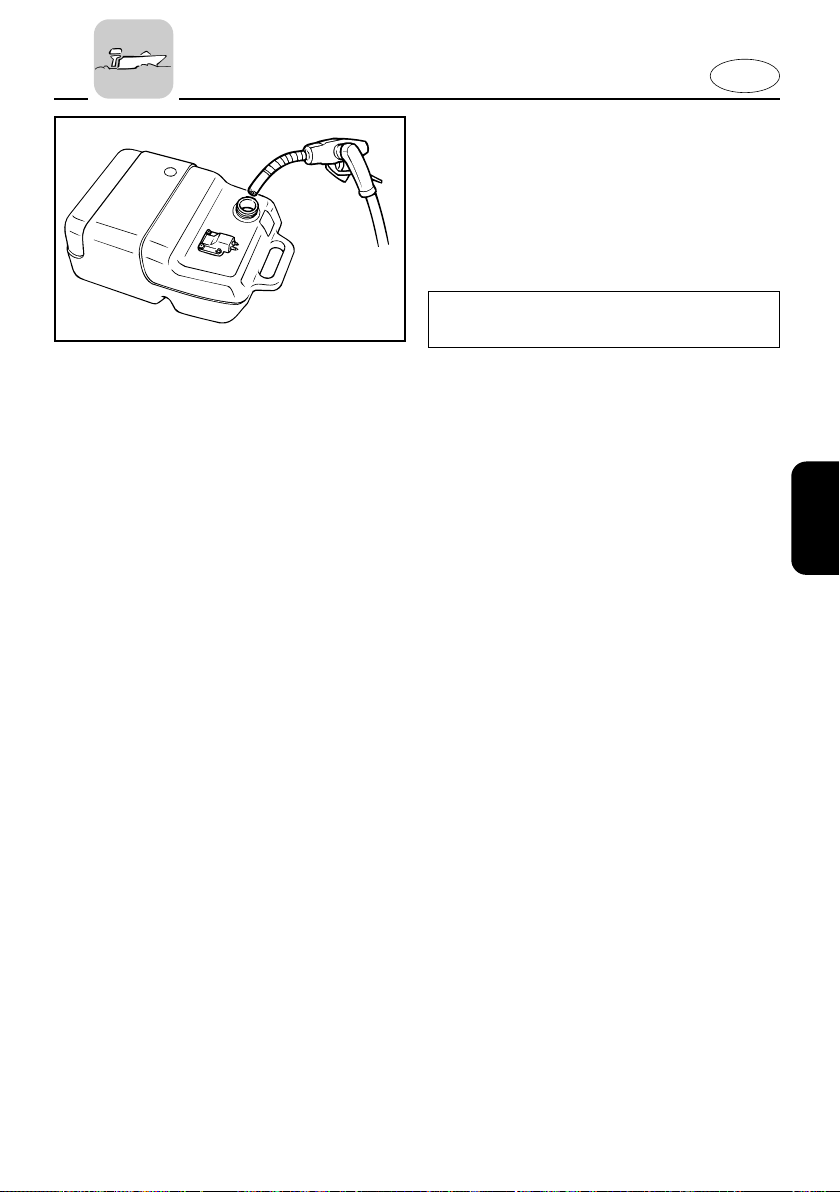
1) Remove the fuel tank cap.
2) Fill the fuel tank carefully.
3) Close the cap securely after refueling.
Wipe up any spilled fuel.
Fuel tank capacity:
Refer to SPECIFICATIONS, page 4-1.
EMU00203
Ring Free Fuel Additive
Gasoline is a precise blend of many different substances, each chosen to give certain characteristics. Gasoline blends have
been changing in recent years in
response to concerns about pollution and
resulting emissions regulations. One of
the most obvious changes has been the
elimination of lead from most fuels.
As gasoline has changed, the amount of
additives such as aromatics and oxygenates has increased. These additives
are important for the engines in passenger cars, but they can have detrimental
effects in marine engines, because of
increased deposits in the combustion
chamber. When enough deposits collect,
piston rings begin sticking. Performance
drops and engine wear increases dramatically.
While many additives available may
reduce deposits, Yamaha recommends
the use of Ring Free Fuel Additive, available from your Yamaha dealer. Ring Free
has repeatedly proven its ability to clean
combustion deposits from inside the
engine, notably the critical piston-ringland area, and fuel system components.
Follow product labeling for use instructions.
3-8
Page 56
E
304042
902053
EMU01147
STARTING ENGINE
w
8 Before starting the engine, make sure
that the boat is tightly moored and that
you can steer clear of any obstructions.
Be sure there are no swimmers in the
water near you.
8 When the air vent screw is loosened,
gasoline (petrol) vapor will be released.
Gasoline (petrol) is highly flammable,
and its vapors are flammable and
explosive. Refrain from smoking, and
keep away from open flames and
sparks while loosening the air vent
screw.
8 This product emits exhaust gases
which contain carbon monoxide, a colorless, odorless gas which may cause
brain damage or death when inhaled.
Symptoms include nausea, dizziness,
and drowsiness. Keep cockpit and
cabin areas well ventilated. Avoid
blocking exhaust outlets.
902061
902025
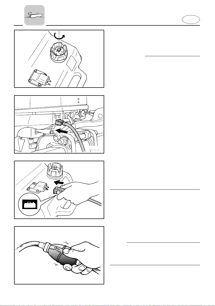
1) If there is an air vent screw on the fuel
tank cap, loosen it 2 or 3 turns.
2) If there is a fuel joint on the motor,
firmly connect the fuel line to the
joint. Then firmly connect the other
end of the fuel line to the joint on the
fuel tank.
NOTE:
During engine operation place the tank
horizontally, or fuel cannot be drawn into
the engine.
3) Squeeze the primer bulb with the out-
let end up until you feel it become
firm.
3-9
Page 57
N
000648
E
EMU01497
PROCEDURE FOR TILLER CONTROL
MODEL
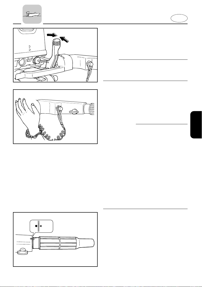
4) Place the gear-shift lever in the neutral position.
NOTE:
The start-in-gear protection device prevents the engine from starting except
when in Neutral.
5) Attach the engine stop switch lanyard
to a secure place on your clothing, or
your arm or leg. Then, install the lock
plate on the other end of the lanyard
in the engine stop switch.
w
8 Attach the engine stop switch lanyard
to a secure place on your clothing, your
arm or leg while operating.
8 Do not attach the lanyard to clothing
that could tear loose. Do not route the
lanyard where it could become entangled, preventing it from functioning.
8 Avoid accidentally pulling the lanyard
during normal operation. Loss of
engine power means the loss of most
steering control. Also, without engine
power, the boat could slow rapidly.
This could cause people and objects in
the boat to be thrown forward.
6) Place the throttle control grip in the
START
START
“START” position.
3-10
Page 58
E
101043**
EMU01005
Manual Start Model
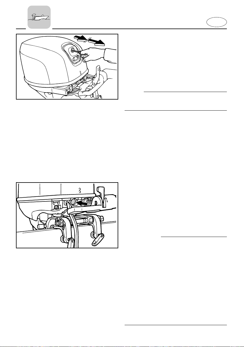
7) Pull the starter handle slowly until
you feel resistance. Then, give a
strong pull straight out to crank and
start the engine. Repeat it, if necessary.
NOTE:
If the warm engine fails to start, open the
throttle slightly and try to start the engine.
8) After the engine starts, return the
starter handle slowly to the original
position before releasing it.
EMU00245
Electric Start Model
7) Push the starter button to start the
starting motor.
8) Immediately the engine starts, release
the starter-switch to return it to its
home position.
cC
8 Do not push the starter-switch when
the engine is running.
8 Do not keep the starter-motor turning
for more than 5 seconds. If the startermotor is run continuously for more
than 5 seconds, the battery will rapidly
become exhausted and it will be
impossible for it to start the engine. If
the engine does not start within 5 seconds, release your hand from starterswitch, wait 10 seconds, and then
crank the engine again.
3-11
Page 59
N
701015
000293
E
EMU00247
PROCEDURE FOR REMOTE
CONTROL MODEL
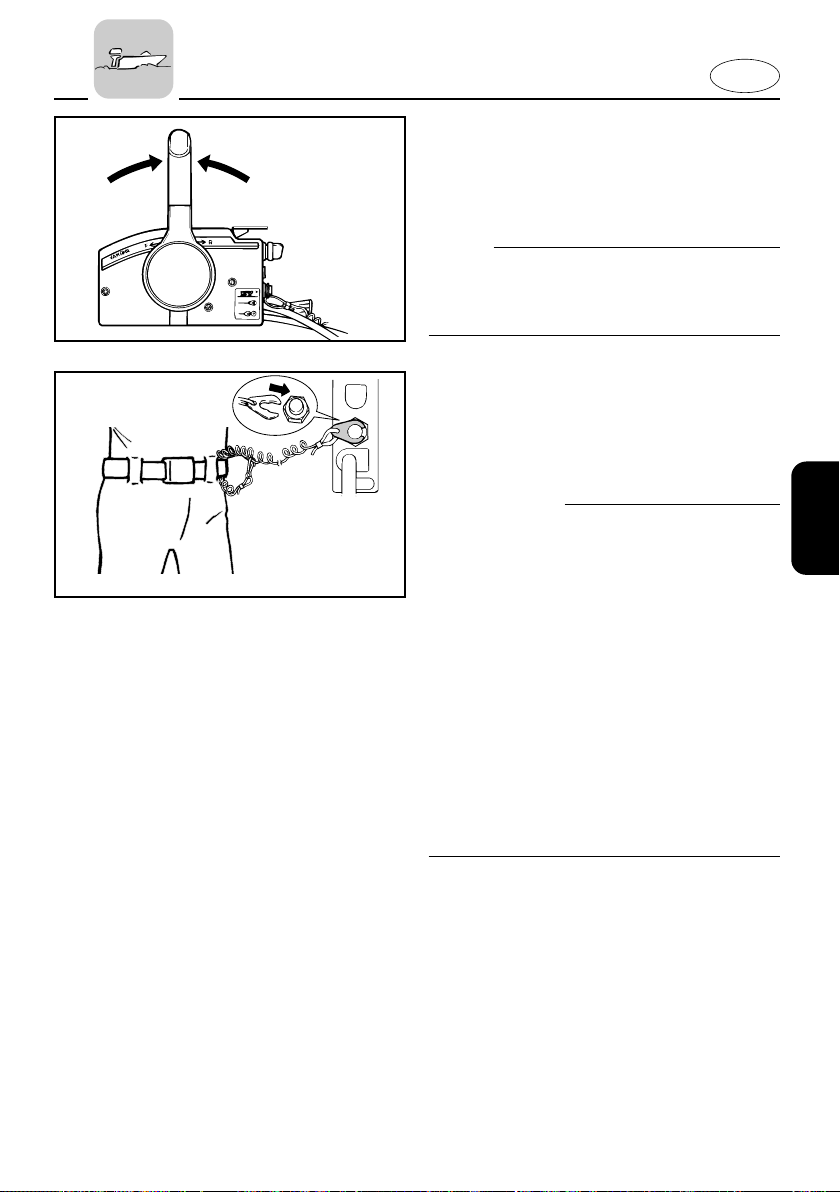
4) Place the remote control lever in the
Neutral position.
NOTE:
The start-in-gear protection device prevents the engine from starting except
when in Neutral.
5) Attach the engine stop switch lanyard
to a secure place on your clothing, or
your arm or leg. Then, install the lock
plate on the other end of the lanyard
in the engine stop switch.
w
8 Attach the engine stop switch lanyard
to a secure place on your clothing, your
arm or leg while operating.
8 Do not attach the lanyard to clothing
that could tear loose. Do not route the
lanyard where it could become entangled, preventing from functioning.
8 Avoid accidentally pulling the lanyard
during normal operation. Loss of
engine power means the loss of most
steering control. Also, without engine
power, the boat could slow rapidly.
This could cause people and objects in
the boat to be thrown forward.
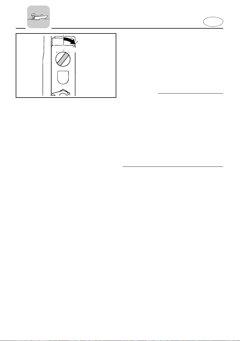
6) Turn the main switch to “ON”.
3-12
Page 60
E
ON
START
OFF
701022
EMU00949
Electric Start Model
7) Turn the main switch to “START”,
and hold it for a maximum of 5 seconds.
8) Immediately after the engine starts,
release the main switch to return it to
“ON”.
cC
8 Do not turn the main switch to
“START” when the engine is running.
8 Do not keep the starter-motor turning
for more than 5 seconds. The battery
will rapidly become exhausted and it
will be impossible for it to start the
engine. If the engine does not start
within 5 seconds, return the main
switch to “ON”, wait 10 seconds, and
then crank the engine again.
3-13
Page 61
E
309016
EMU00258
WARMING UP ENGINE
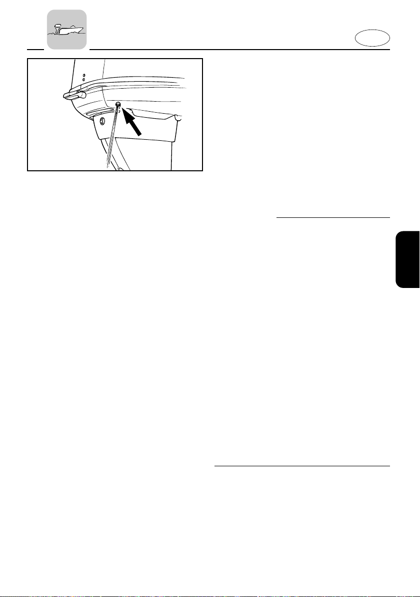
1) Before beginning operation, allow the
engine to warm up at idling speed for
3 minutes. (Failure to do this will
shorten engine life.)
2) Be sure the low oil pressure warning
indicator goes off after starting the
engine.
3) Check for a steady flow of water from
the cooling-water pilot hole.
cC
8 If the low oil pressure indicator does
not go off after the engine starts, stop
the engine. Otherwise, serious engine
damage could occur. Check the oil level
and add oil if necessary. If the cause for
the low oil pressure warning indicator
cannot be found, consult your Yamaha
dealer.
8 A continuous flow of water from the
pilot hole shows that the water pump
is pumping water through the cooling
passages. If water is not flowing out of
the pilot hole at all times while the
engine is running, do not continue to
run the engine. Overheating and serious damage could occur. Stop the
engine and check to see if the water
inlet on the lower casing is blocked. If
the problem cannot be found and corrected, consult your Yamaha dealer.
3-14
Page 62
E
START
EMU00261
SHIFTING
w
Before shifting, make sure there are no
swimmers or obstacles in the water near
you.
cC
To change the shifting position from forward to reverse or vice-versa, close the
throttle first so that the engine idles (or
runs at low speeds).
EMU00265
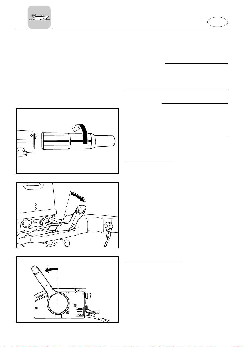
FORWARD
Tiller control model
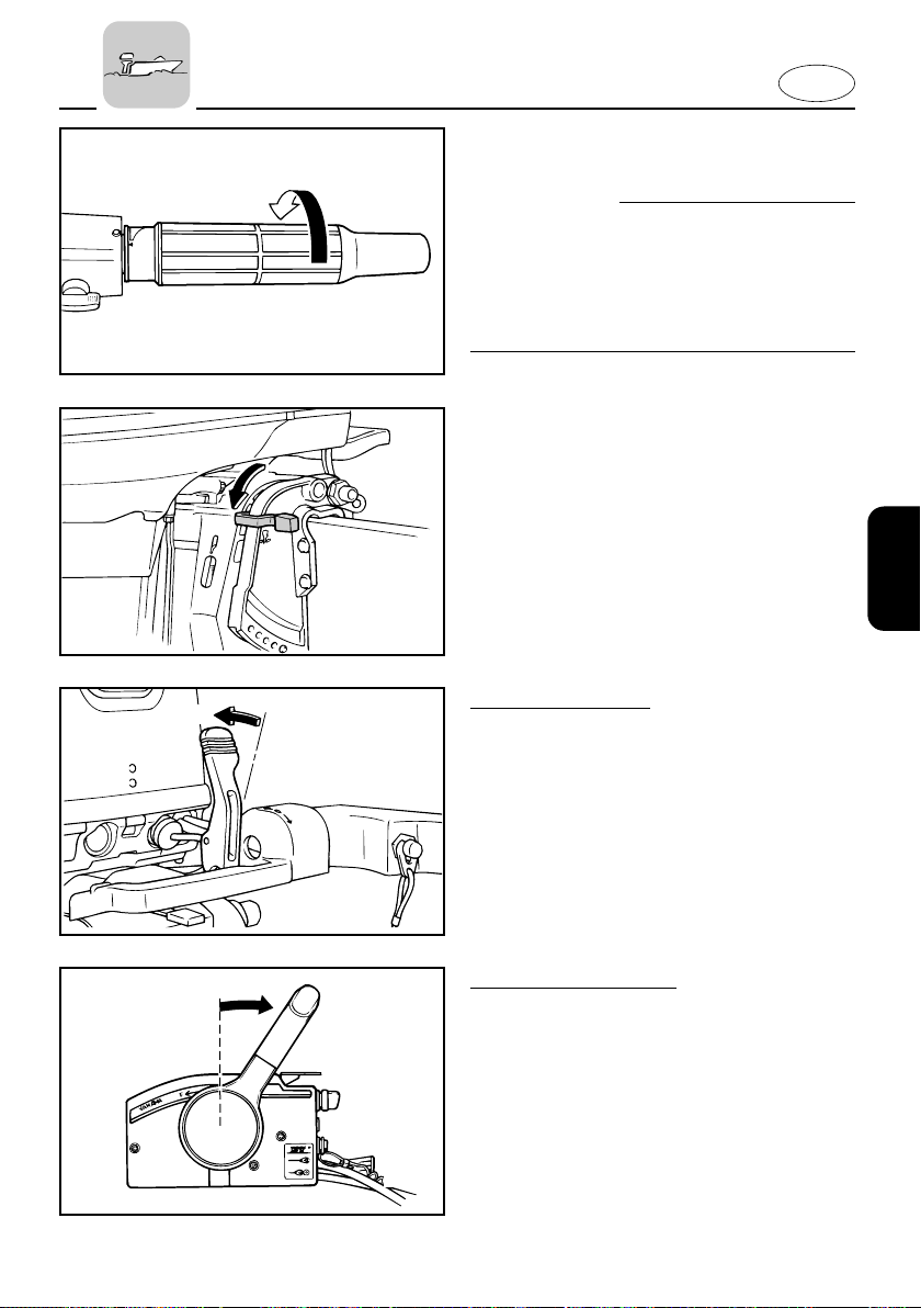
1) Place the throttle control grip in the
fully closed position.
2) Turn the gear-shift lever quickly and
N
firmly from Neutral to Forward.
F
F
N
701043
Remote control model
Pull up the neutral interlock trigger if
equipped and move the remote control
lever quickly and firmly from Neutral to
Forward.
3-15
Page 63
START
402073*
E
EMU01326
REVERSE
w
When operating in Reverse, go slowly. Do
not open the throttle more than half.
Otherwise, the boat may become unstable, which could result in loss of control
and an accident.
1) Place the throttle control grip in the
fully closed position (for Tiller control
model).
2) Check that the tilt-lock lever (for
Manual tilt/Hydro-tilt model) is in the
locked position.
R
N
3) Turn the gear-shift lever quickly and
firmly from Neutral to Reverse.
Tiller control model
N
R
Remote control model
3) Pull up the neutral interlock trigger if
equipped and move the remote control lever quickly and firmly from
Neutral to Reverse.
701044
3-16
Page 64
E
506021
304043
EMU00273
STOPPING ENGINE
Let it cool off for a few minutes at idle or
low speed first. Stopping the engine
immediately after operating at high speed
is not recommended.
OFF
ON
START
701023
902052
EMU00277
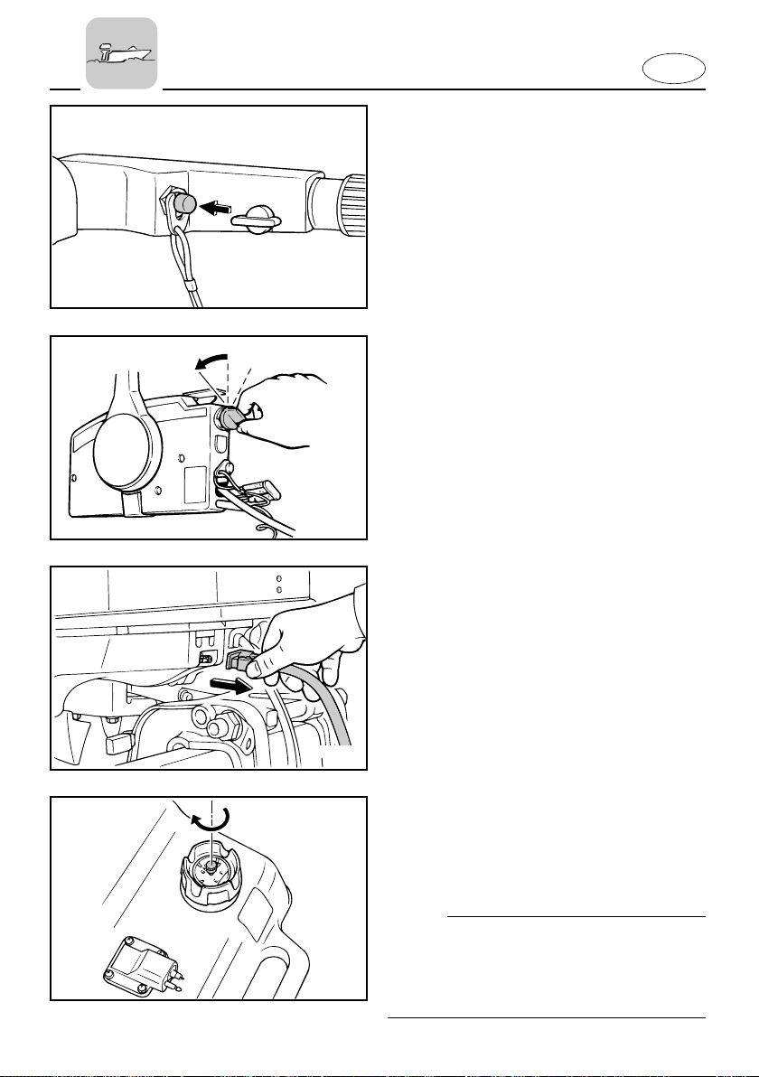
1) Push and hold the engine stop button
or turn the main switch to “OFF”.
2) If the fuel joints are provided, discon-
nect the fuel line from the motor after
stopping the engine.
3) Tighten the air vent screw on the fuel
tank cap after stopping the engine, if
it is equipped.
4) Remove the key if the boat will be left
unattended.
NOTE:
The engine can also be stopped by
pulling the lanyard and removing the lock
plate from the engine stop lanyard switch
(then turning the main switch to “OFF”).
3-17
Page 65
E
000910
q
EMU01412
TRIMMING OUTBOARD
MOTOR
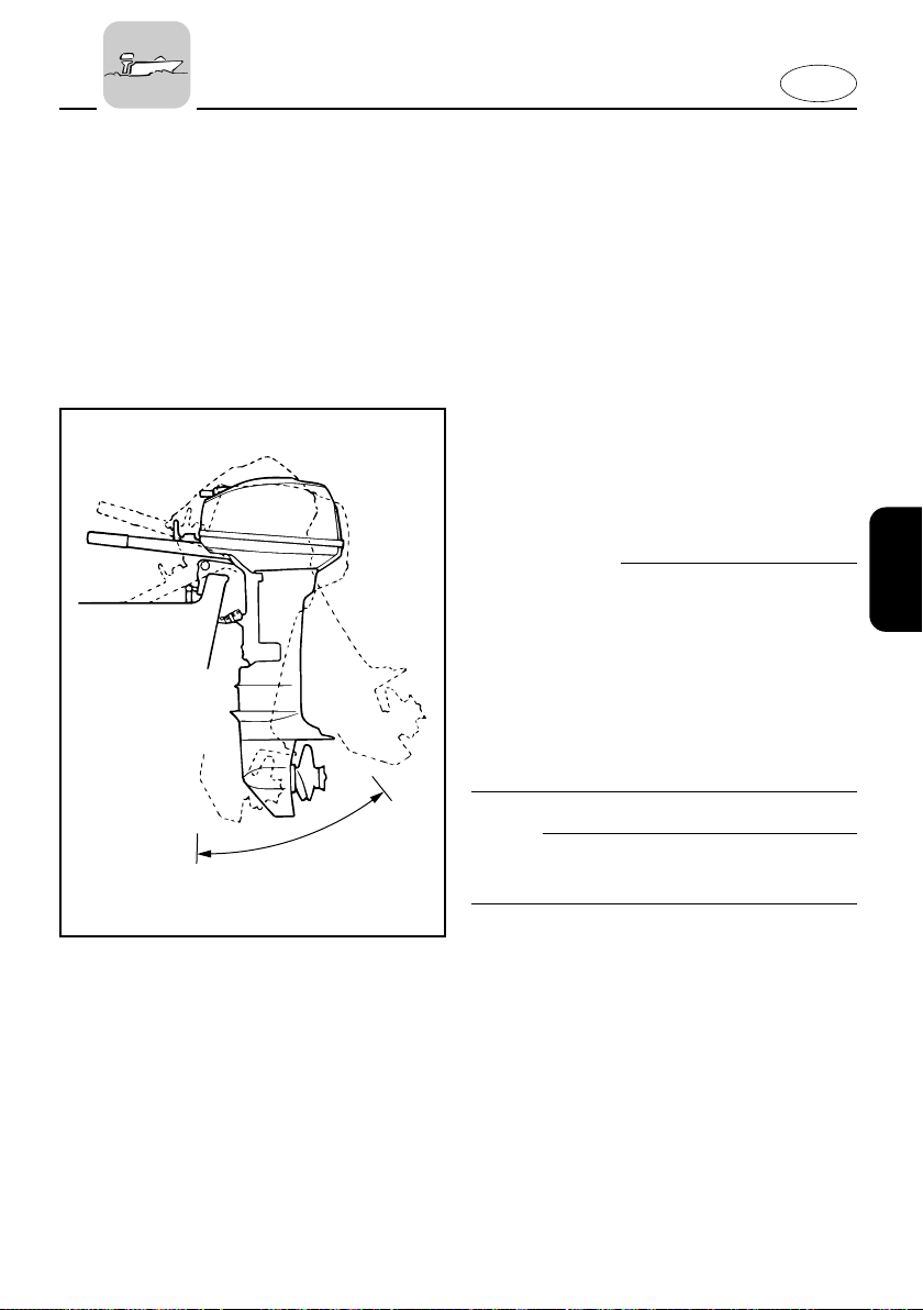
The trim angle of the outboard motor
helps determine the position of the bow
of the boat in the water. The correct trim
angle will help improve performance and
fuel economy while reducing strain on the
engine. The correct trim angle depends
upon the combination of boat, engine,
and propeller. Correct trim is also affected
by variables such as the load in the boat,
sea conditions, and running speed.
w
Excessive trim for the operating conditions (either trim up or trim down) can
cause boat instability and can make
steering the boat more difficult. This
increases the possibility of an accident. If
the boat begins to feel unstable or is hard
to steer, slow down and/or readjust the
trim angle.
NOTE:
Refer to the section “ADJUSTING TRIM
ANGLE” for instructions on usage.
1 Trim operating angle
3-18
Page 66
E
404012*
q
ADJUSTING TRIM ANGLE
EMU00951*
Manual tilt model
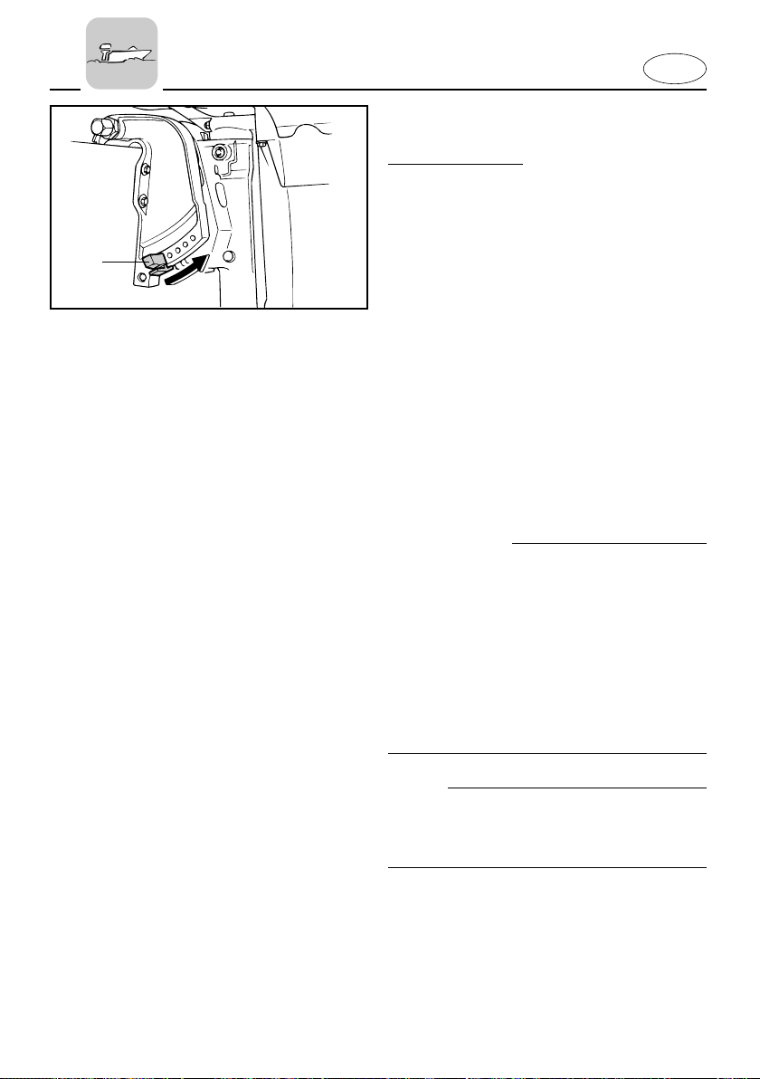
There are 4 or 5 holes provided in the
clamp bracket to adjust the outboard
motor trim angle.
1) Stop the engine.
2) Remove the trim angle adjusting rod
1 from the clamp bracket while tilting
the motor up slightly.
3) Reposition the rod in the desired hole.
To raise the bow (“trim-out”), move the
rod away from the transom.
To lower the bow (“trim-in”), move the
rod toward the transom.
Make test runs with the trim set to different angles to find the position that works
best for your boat and operating conditions.
w
8 Stop the engine before adjusting the
trim angle.
8 Use care to avoid being pinched when
removing or installing the rod.
8 Use caution when trying a trim position
for the first time. Increase speed gradually and watch for any signs of instability or control problems. Improper trim
angle can cause loss of control.
NOTE:
The outboard motor trim angle can be
changed approximately 4 degrees by
shifting the trim adjusting-rod one hole.
3-19
Page 67
E
UP
DN
701034**
UP
DN
q
EMU01401
Power Trim/Tilt Model
w
8 Be sure all people are clear of the out-
board motor when adjusting the
trim/tilt angle, also be careful not to
pinch any body parts between the drive
unit and clamp bracket.
8 Use caution when trying a trim position
for the first time. Increase speed gradually and watch for any signs of instability or control problems.
8 Use the power trim/tilt switch located
on the bottom engine cowling (if
equipped) only when the boat is at a
complete stop with the engine off.
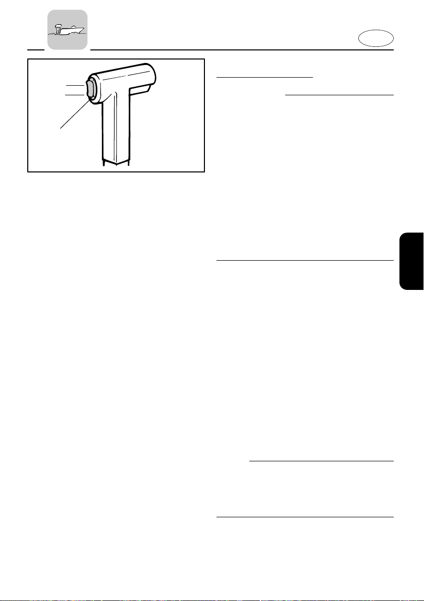
The outboard motor trim angle can be
adjusted operating the power trim/tilt
switch 1.
To raise the bow (“trim-out”), push the
switch UP.
To lower the bow (“trim-in”), push the
switch DN.
Make test runs with the trim set to different angles to find the position that works
best for your boat and operating conditions.
NOTE:
To adjust the trim angle while the boat is
moving, use the power trim and tilt
switch located on the remote control
device or tiller handle, if so equipped.
3-20
Page 68
105011
q
w
E
EMU00282
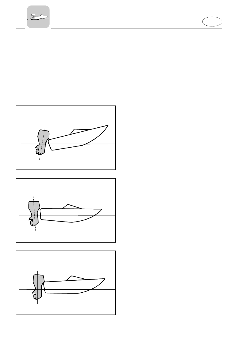
Bow Up
When the boat is on plane, a bow-up attitude result in less drag, greater stability
and efficiency. This is generally when the
keel line of the boat is up about 3 to 5
degrees. When trimmed out, the boat
may have more tendency to steer to one
side or the other. Compensate for this as
you steer. The trim tab can also be adjusted to help offset this effect.
Too much trim-out puts the bow of the
boat too high in the water. Performance
and economy are decreased because the
hull of the boat is pushing the water and
there is more air drag.
Excessive trim-up can cause the propeller
to ventilate, which reduces performance
further. When trimmed-out too much, a
boat may “porpoise” (hop in the water),
which could throw the operator and passengers overboard.
EMU00283
Bow Down
When the bow of the boat is down, it is
easier to accelerate from a standing start
onto plane.
e
105013
105015
Too much trim-in causes the boat to
“plow” through the water, decreasing
fuel economy and making in hard to
increase speed.
Operating with excessive trim-in at higher
speeds also makes the boat unstable.
Resistance at the bow is greatly
increased, heightening the danger of
“bow steering” and making operation difficult and dangerous.
1 Bow up
2 Bow down
3 Optimum angle
3-21
Page 69
E
105031
EMU00285
TILTING UP/DOWN
If the engine will be stopped for some
time, or if the boat is moored in shallows,
the engine should be tilted up to protect
the propeller and casing from damage by
collision with obstructions, and also to
reduce salt corrosion.
cC
8 Before tilting the motor, follow the pro-
cedures under “STOPPING ENGINE”.
Never tilt the motor while the engine is
running. Severe damage from overheating can result.
8 Do not tilt up the engine by pushing
the steering handle as this could break
the handle.
w
Be sure all people are clear of the outboard motor when adjusting the tilt
angle, also be careful not to pinch any
body parts between the drive unit and
engine bracket.
w
Leaking fuel is a fire hazard. Disconnect
the fuel line if the engine will be tilted for
more than a few minutes. Otherwise, fuel
may leak. (If the fuel connector is provided on the motor.)
3-22
Page 70
402071
304043
E
EMU00290
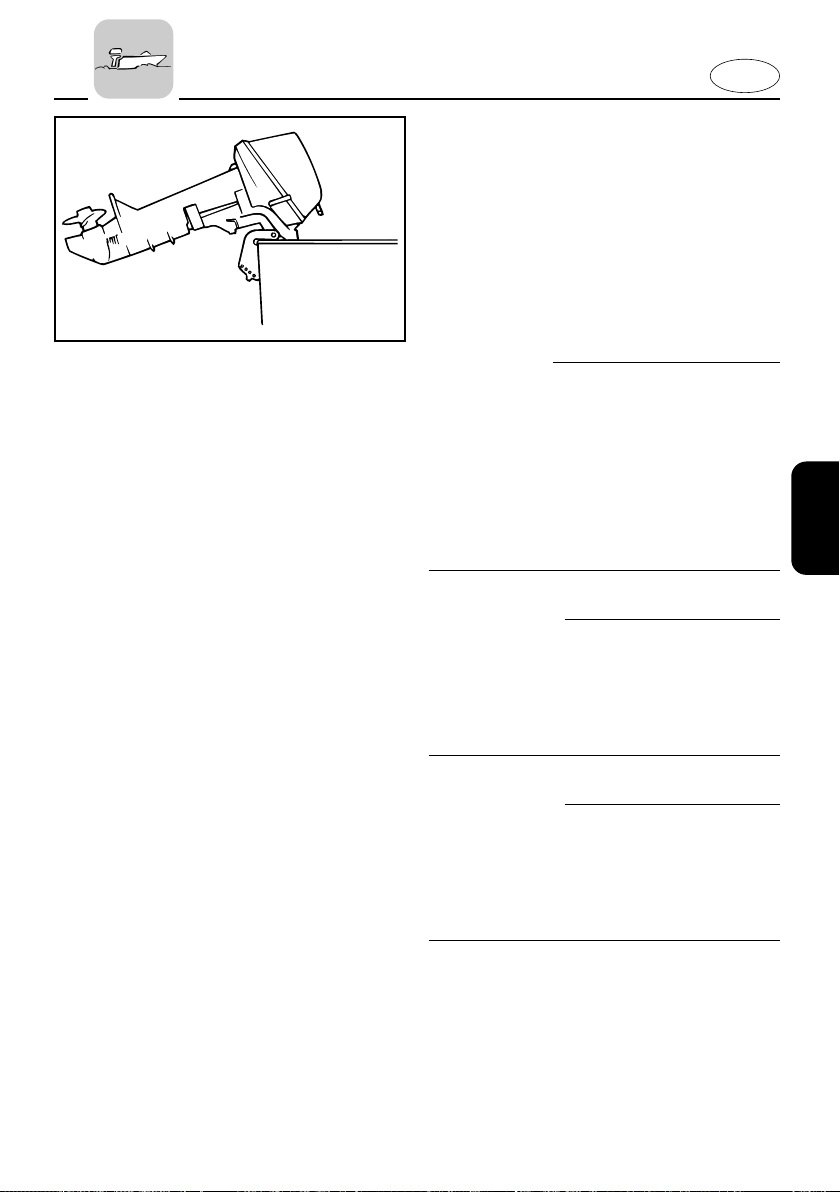
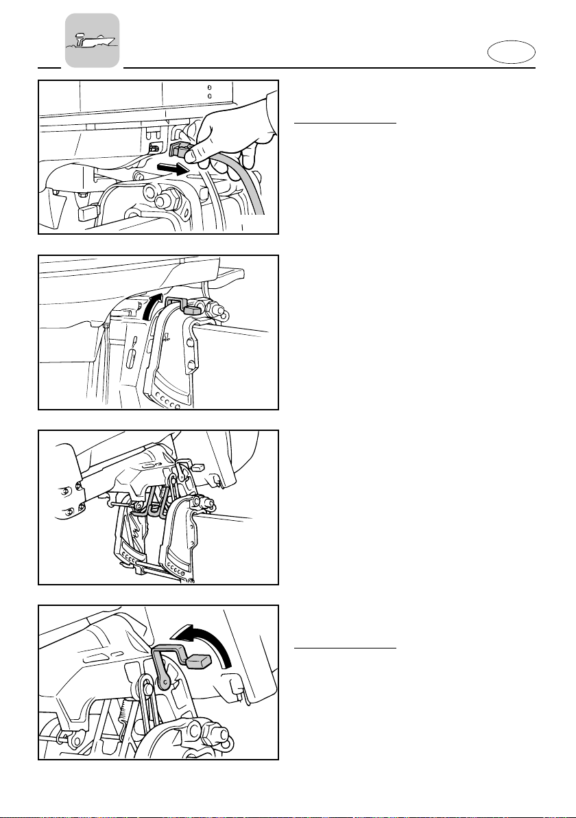
PROCEDURE FOR TILTING UP
Manual tilt model
1) Place the gear shift lever in Neutral.
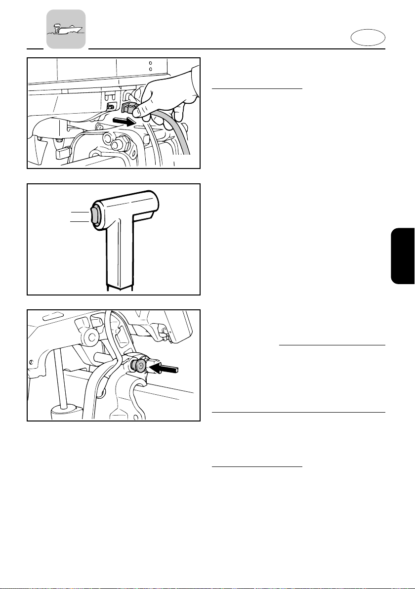
2) Remove the fuel line connection from
the motor.
3) Place the tilt lock lever in the release
position.
4) Hold the rear of the top cowling with
one hand and fully tilt the engine up.
5) The tilt support bar turns to the
locked position automatically.
403052
EMU00300
PROCEDURE FOR TILTING DOWN
Manual tilt model
1) Place the tilt lock lever in the lock
position.
2) Slightly tilt up the engine until the tilt
support bar is released automatically.
3) Tilt down the engine.
402074
3-23
Page 71
UP
DN
701034*
UP
DN
304043
403054
E
EMU00296
PROCEDURE FOR TILTING UP
Power trim/tilt model
1) Remove the fuel-line connection from
the motor.
2) Push the power trim/tilt switch “UP”
until the outboard has tilted up completely.
3) Push the tilt support knob into the
clamp bracket to support the engine.
w
After tilting the engine, be sure to support it with the tilt support knob.
Otherwise, the engine could fall back
down suddenly if oil in the power
trim/tilt unit should lose pressure.
EMU00305
PROCEDURE FOR TILTING DOWN
Power trim/tilt model
1) Push the power trim/tilt switch “UP”
until the engine is supported by the
3-24
tilt rod.
2) Pull out the tilt support knob.
3) Push the power trim/tilt switch “DN”
(Down) to lower the engine to the
desired position.
Page 72
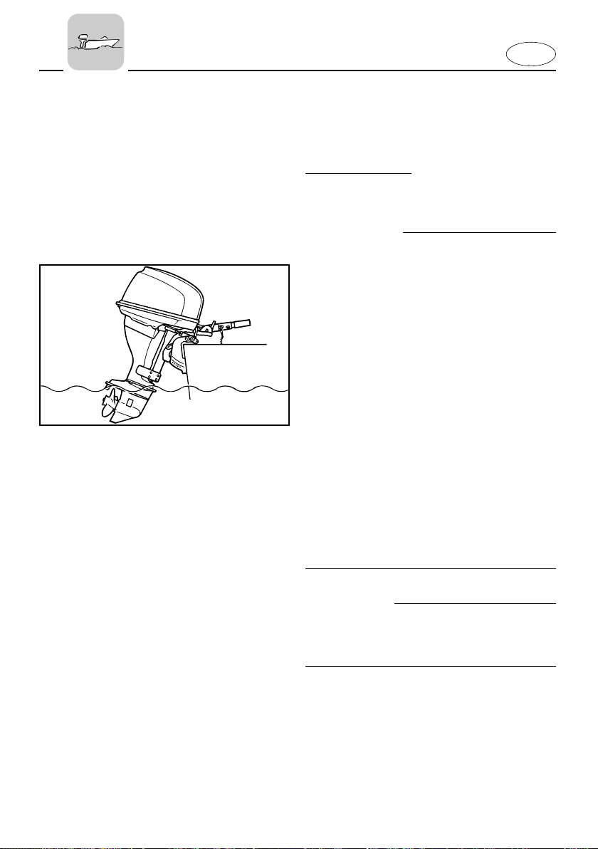
E
000911
EMU00306
CRUISING IN SHALLOW
WATER
Manual tilt model
The outboard motor can be tilted up partially to allow operation in shallow water.
w
8 Place the gear shift in the Neutral posi-
tion before using the shallow water
cruising system.
8 Run the boat at the lowest possible
speed when using the shallow water
cruising system. The tilt-lock mechanism does not work while the shallow
water cruising system is being used.
Hitting an underwater obstacle could
cause the engine to lift out of the
water, resulting in loss of control.
8 Use extra care when operating in
reverse. Too much reverse thrust can
cause the engine to lift out of the
water, increasing the chance of accident and personal injury.
8 Return the engine to its normal posi-
tion as soon as the boat is back in
deeper water.
cC
Place the gear-shift in the Neutral position before using the shallow water cruising system.
3-25
Page 73
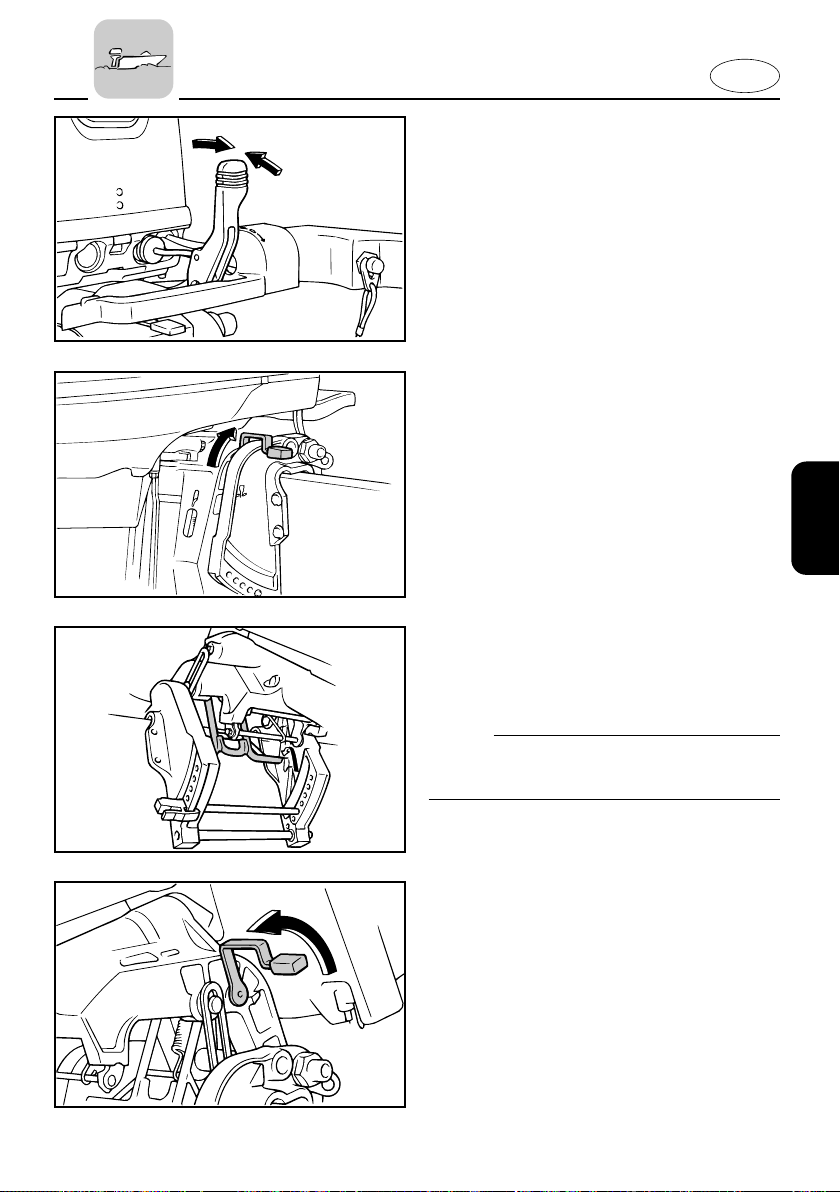
E
403051
402071
N
EMU00310
PROCEDURE
1) Place the gear shift lever in the neutral position.
2) Place the tilt lock lever in the release
position.
3) Slightly tilt up the engine. The tiltsupport bar will lock automatically,
supporting the engine in a partially
raised position.
NOTE:
This motor has 2 positions for shallow
water cruising.
RETURNING TO ORIGINAL POSITION
1) Place the tilt lock lever in the lock
position.
2) Slightly tilt up the engine until the tiltsupport bar automatically returns to
the free position.
3) Then, slowly lower the engine to the
normal position.
402074
3-26
Page 74

E
EMU00316
CRUISING IN OTHER
CONDITIONS
CRUISING IN SALT WATER
After operating in salt water, wash out the
cooling-water passages with fresh water
to prevent them from becoming cloggedup with salt deposits.
NOTE:
Refer to cooling system flushing instructions in “TRANSPORTING AND STORING
OUTBOARD MOTOR”.
CRUISING IN TURBID WATER
It is strongly recommended that the
optional chromium-plated water-pump kit
be installed if the outboard is to be used
in turbid (muddy) water conditions.
3-27
Page 75
E
EMU00317
Chapter 4
MAINTENANCE
SPECIFICATIONS .....................................4-1
TRANSPORTING AND STORING
OUTBOARD MOTOR ...............................4-4
Trailering outboard motor ...................4-4
Storing outboard motor .......................4-5
PERIODIC MAINTENANCE....................4-10
Replacement parts..............................4-10
Maintenance chart ..............................4-11
Greasing...............................................4-12
Cleaning and adjusting spark plug ...4-14
Checking fuel system .........................4-16
Inspecting fuel filter ............................4-17
Adjusting idling speed .......................4-18
Changing engine oil............................4-19
Checking timing belt...........................4-21
Replacing fuse.....................................4-22
Checking wiring and connectors.......4-22
Exhaust leakage ..................................4-22
Water leakage......................................4-22
Checking power trim and tilt
system ..................................................4-23
Checking propeller..............................4-24
Changing gear oil................................4-26
Cleaning fuel tank ...............................4-28
Inspecting and replacing anode(s)....4-29
Checking battery .................................4-30
Checking bolts and nuts.....................4-32
Cleaning cooling-water passages .....4-33
Motor exterior .....................................4-34
Coating the boat bottom ....................4-34
1
2
3
4
5
6
Page 76
EMU00322*
SPECIFICATIONS
Model
Item
DIMENSIONS
Overall Length mm (in.)
Overall Width mm (in.)
Overall Height S/L/X mm (in.)
Transom height S/L/X mm (in.)
Weight S/L/X kg (lb.)
PERFORMANCE
Full throttle operating range r/min
Maximum output kW (HP) @ r/min
Idling speed (Neutral) r/min
ENGINE
Type
Displacement cm
Bore × stroke mm (in.)
Ignition system
Spark plug NGK
Spark plug gap mm (in.)
Control system
Starting system
Valve clearance (cold engine) IN mm (in.)
EX mm (in.)
Battery
Min. cold cranking amps (CCA/SAE) amps at -18°C (-0.4°F)
Min. marine cranking amps (MCA/ABYC)
Min. reserve capacity (RC/SAE) minutes
Alternator output V-A (W)
Starting carburetion system
DRIVE UNIT
Gear positions
Gear ratio
Trim and tilt system
Propeller mark
FUEL AND OIL
Recommended fuel
Fuel tank capacity I (US gal, lmp qt)
Recommended engine oil
Engine oil capacity (without oil filter) I (US qt, Imp qt)
(with oil filter) I (US qt, Imp qt)
Recommended gear oil
Gear oil capacity cm
TIGHTENING TORQUE
Spark plug N·m (kgf·m, lb·ft)
Propeller nut N·m (kgf·m, lb·ft)
Engine oil drain bolt N·m (kgf·m, lb·ft)
Engine oil filter N·m (kgf·m, lb·ft)
Unit F25MHB
3
(cu.in.)
amps at 0°C (32°F)
P.O.N.
API
SAE
3
(US oz, Imp oz)
4-1
E
1,151 (45.3)
430 (16.9)
1,148 (45.2)/1,275 (50.2)/1,354(53.5)
423 (16.7)/550 (21.7)/636(25.0)
62 (137)/64 (141)/66(146)
5,000–6,000
18.4 (25.0) @ 5,500
925–1,025
4-stroke, OHC, L2
498 (30.39)
65.0 × 75.0 (2.56 × 2.95)
CDI system
DPR6EA-9
0.8–0.9 (0.031–0.035)
Tiller control
Manual recoil starter
0.15–0.25 (0.006–0.010)
0.25–0.35 (0.010–0.014)
—
—
—
12-(80)
Prime start
Forward-Neutral-Reverse
2.08 (27/13)
Manual
F
Regular unleaded gasoline
(Minimum 86)
25 (6.60, 5.50)
4-stroke motor oil
SE, SF, SG, SH, SJ
10W-30, 10W-40
1.7 (1.80, 1.50)
1.9 (2.00, 1.67)
Hypoid gear oil (SAE90)
320 (10.81, 11.27)
18 (1.8, 13)
35 (3.5, 25)
28 (2.8, 20)
18 (1.8, 13)
Page 77
F25EHB F25ERB F25TRB
E
1,151 (45.3)
430 (16.9)
1,148 (45.2)/1,275 (50.2)/1,354 (53.3)
423 (16.7)/550 (21.7)/636 (25.0)
66 (146)/68 (150)/70 (154)
5,000–6,000
18.4 (25.0) @ 5,500
875–975
4-stroke, OHC, L2
498 (30.39)
65.0 × 75.0 (2.56 × 2.95)
CDI system
DPR6EA-9
0.8–0.9 (0.031–0.035)
Tiller control
Electric start
0.15–0.25 (0.006–0.010)
0.25–0.35 (0.010–0.014)
245
323
52
12-15
Prime start
Forward-Neutral-Reverse
2.08 (27/13)
Manual tilt
F
703 (27.7)
376 (14.8)
1,148 (45.2)/1,275 (50.2)/—
423 (16.7)/550 (21.7)/—
65 (143)/67 (148)/—
5,000–6,000
18.4 (25.0) @ 5,500
875–975
4-stroke, OHC, L2
498 (30.39)
65.0 × 75.0 (2.56 × 2.95)
CDI system
DPR6EA-9
0.8–0.9 (0.031–0.035)
Remote control
Electric start
0.15–0.25 (0.006–0.010)
0.25–0.35 (0.010–0.014)
245
323
52
12-15
Prime start
Forward-Neutral-Reverse
2.08 (27/13)
Manual tilt
F
703 (27.7)
376 (14.8)
—/1,275 (50.2)/—
—/550 (21.7)/—
—/71 (157)/—
5,000–6,000
18.4 (25.0) @ 5,500
875–975
4-stroke, OHC, L2
498 (30.39)
65.0 × 75.0 (2.56 × 2.95)
CDI system
DPR6EA-9
0.8–0.9 (0.031–0.035)
Remote control
Electric start
0.15–0.25 (0.006–0.010)
0.25–0.35 (0.010–0.014)
245
323
52
12-15
Prime start
Forward-Neutral-Reverse
2.08 (27/13)
Power trim and tilt
F
Regular unleaded gasoline
(Minimum 86)
25 (6.60, 5.50)
4-stroke motor oil
SE, SF, SG, SH, SJ
10W-30, 10W-40
1.7 (1.80, 1.50)
1.9 (2.00, 1.67)
Hypoid gear oil (SAE90)
320 (10.81, 11.27)
18 (1.8, 13)
35 (3.5, 25)
28 (2.8, 20)
18 (1.8, 13)
Regular unleaded gasoline
(Minimum 86)
25 (6.60, 5.50)
4-stroke motor oil
SE, SF, SG, SH, SJ
10W-30, 10W-40
1.7 (1.80, 1.50)
1.9 (2.00, 1.67)
Hypoid gear oil (SAE90)
320 (10.81, 11.27)
18 (1.8, 13)
35 (3.5, 25)
28 (2.8, 20)
18 (1.8, 13)
4-2
Regular unleaded gasoline
(Minimum 86)
25 (6.60, 5.50)
4-stroke motor oil
SE, SF, SG, SH, SJ
10W-30, 10W-40
1.7 (1.80, 1.50)
1.9 (2.00, 1.67)
Hypoid gear oil (SAE90)
320 (10.81, 11.27)
18 (1.8, 13)
35 (3.5, 25)
28 (2.8, 20)
18 (1.8, 13)
Page 78
EMU00322*
SPECIFICATIONS
Model
Item
DIMENSIONS
Overall Length mm (in.)
Overall Width mm (in.)
Overall Height S/L/X mm (in.)
Transom height S/L/X mm (in.)
Weight S/L/X kg (lb.)
PERFORMANCE
Full throttle operating range r/min
Maximum output kW (HP) @ r/min
Idling speed (Neutral) r/min
ENGINE
Type
Displacement cm
Bore × stroke mm (in.)
Ignition system
Spark plug NGK
Spark plug gap mm (in.)
Control system
Starting system
Valve clearance (cold engine) IN mm (in.)
EX mm (in.)
Battery
Min. cold cranking amps (CCA/SAE) amps at -18°C (-0.4°F)
Min. marine cranking amps (MCA/ABYC)
Min. reserve capacity (RC/SAE) minutes
Alternator output V-A (W)
Starting carburetion system
DRIVE UNIT
Gear positions
Gear ratio
Trim and tilt system
Propeller mark
FUEL AND OIL
Recommended fuel
Fuel tank capacity I (US gal, lmp qt)
Recommended engine oil
Engine oil capacity (without oil filter) I (US qt, Imp qt)
(with oil filter) I (US qt, Imp qt)
Recommended gear oil
Gear oil capacity cm
TIGHTENING TORQUE
Spark plug N·m (kgf·m, lb·ft)
Propeller nut N·m (kgf·m, lb·ft)
Engine oil drain bolt N·m (kgf·m, lb·ft)
Engine oil filter N·m (kgf·m, lb·ft)
Unit T25TRB
3
(cu.in.)
amps at 0°C (32°F)
P.O.N.
API
SAE
3
(US oz, Imp oz)
4-3
E
713 (28.1)
373 (14.7)
—/1,311 (51.6)/1,425 (56.1)
—/528 (20.8)/642 (25.3)
—/87 (192)/90 (198)
5,000–6,000
18.4 (25.0) @ 5,500
925–1,025
4-stroke, OHC, L2
498 (30.39)
65.0 × 75.0 (2.56 × 2.95)
CDI system
DPR6EA-9
0.8–0.9 (0.031–0.035)
Remote control
Electric start
0.15–0.25 (0.006–0.010)
0.25–0.35 (0.010–0.014)
245
323
52
12-15
Prime start
Forward-Neutral-Reverse
2.42 (29/12)
Power trim and tilt
G
Regular unleaded gasoline
(Minimum 86)
25 (6.60, 5.50)
4-stroke motor oil
SE, SF, SG, SH, SJ
10W-30, 10W-40
1.9 (2.00, 1.67)
2.1 (2.22, 1.85)
Hypoid gear oil (SAE90)
430 (14.54, 15.14)
18 (1.8, 13)
35 (3.5, 25)
28 (2.8, 20)
18 (1.8, 13)
Page 79
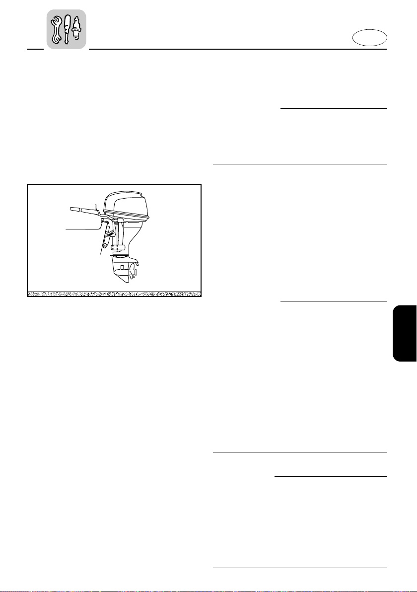
E
001213
EMU01369
TRANSPORTING AND
STORING OUTBOARD MOTOR
w
Leaking fuel is a fire hazard. When transporting and storing the outboard motor,
close the air vent screw and fuel cock to
prevent fuel from leaking.
EMU00326
TRAILERING OUTBOARD MOTOR
The motor should be trailered and stored
in the normal running position. If there is
insufficient road clearance in this position,
then trailer the motor in the tilt position
using a motor support device such as a
transom saver bar.
For further details, consult your Yamaha
dealer.
w
8 Never get under the lower unit while it
is tilted, even if a motor support bar is
used. Severe injury could occur if the
outboard accidentally falls.
8 USE CARE when transporting fuel tank,
whether in a boat or car.
8 DO NOT fill fuel container to maximum
capacity. Gasoline will expand considerably as it warms up and can build up
pressure in the fuel container. This can
cause fuel leakage and a potential fire
hazard.
cC
Do not use the tilt support lever/knob
when trailering the boat. The outboard
motor could shake loose from the tilt
support and fall. If the motor can not be
trailered in the down position, use an
additional support device to secure it in
the up position.
4-4
Page 80
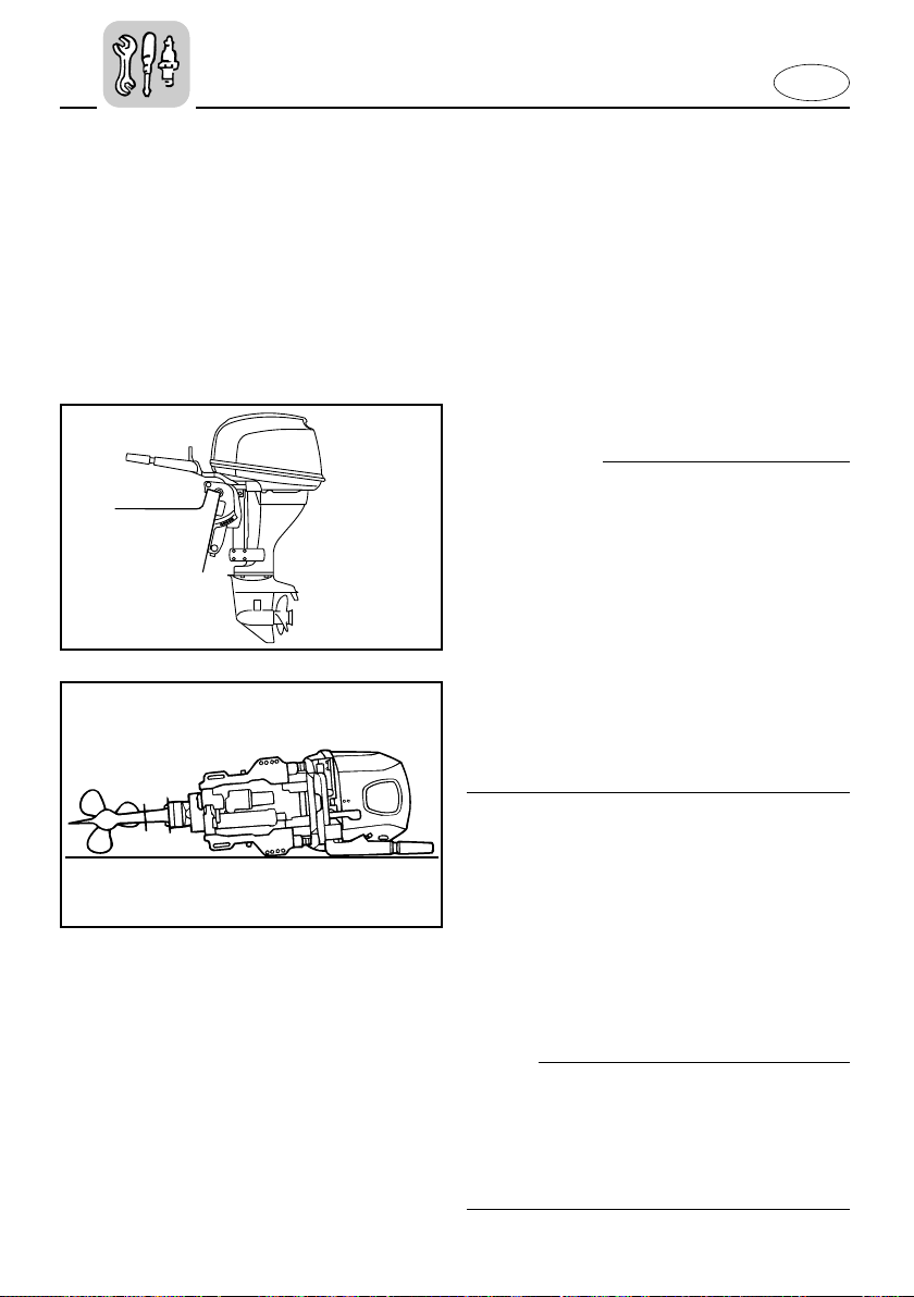
000912
q
w
E
EMU00330
STORING OUTBOARD MOTOR
When storing your Yamaha outboard for
prolonged periods of time, (2 months or
longer), several important procedures
must be performed to prevent expensive
damage.
It is advisable to have your outboard serviced by an authorized Yamaha dealer
prior to storage. However, the following
procedures can be performed by you, the
owner, with a minimum of tools.
cC
8 To prevent problems which can be
caused by oil entering the cylinder from
the sump, keep the engine in the attitude shown when transporting and
storing it.
8 Do not place the engine on its side
before the cooling water has drained
from it completely, or water may enter
the cylinder through the exhaust port
and cause problems.
8 Store the engine in a dry, well-ventilat-
ed place, not in direct sunlight.
102**2
1 Vertical position
2 Horizontal position
EMU00335
Filling Fuel Tank
Fill the fuel tank with fresh fuel and add
one ounce of “Yamaha Fuel Conditioner
and Stabilizer” (Part No. LUB-FUELC-12-
00) to each gallon of fuel.
NOTE:
The use of “Yamaha Fuel Conditioner and
Stabilizer” eliminates the need to drain
the fuel system. Consult your Yamaha
dealer or other qualified mechanic if the
fuel system is to be drained instead.
4-5
Page 81
E
EMU00338
Flushing Cooling System and Fogging
Engine
Cooling system flushing is essential to
prevent the cooling system from clogging
up with salt, sand, or dirt. In addition, fogging of the engine is mandatory to prevent expensive engine damage due to
rust. Perform the flushing and fogging at
the same time.
w
8 Do not touch or remove electrical parts
when starting or during operation.
8 Keep hands, hair and clothes away
from flywheel and other rotating parts
while engine is running.
EMU00339
8 Flushing in a Water Tank
cC
If the fresh water level is below the level
of the anti-cavitation plate, or if the water
supply is insufficient, engine seizure may
occur.
1) Remove the engine top cowling and
silencer cover.
2) Install the outboard motor on the
water tank.
3) Fill the tank with fresh water to above
the level of the anti-cavitation plate.
4) Run the engine at a fast idle for 10~15
minutes.
5) Just prior to turning off the engine,
quickly spray “Yamaha Stor-Rite
Engine Fogging Oil” (Part No. LUBSTRRT-12-00) alternately into each
carburetor. When properly done, the
engine will smoke excessively and
almost stall.
4-6
Page 82
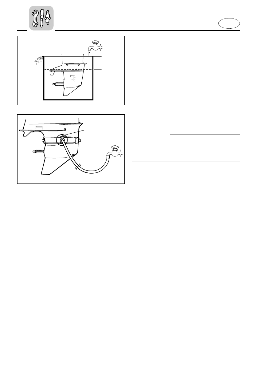
605024
q
w
q
605014*
E
6) Remove the motor from the water
tank.
7) Install the silencer cover and top
cowling.
1 Water surface
2 Lowest water level
EMU00342
8 Flushing with the Flushing Attachment
cC
Avoid running the outboard at high
speed while on the flushing attachment,
or overheating could occur.
1) Remove the top cowling and the pro-
peller.
2) Install a flushing attachment 1 to the
cooling water inlet.
3) Run the engine at a fast idle for 10~15
minutes supplying fresh water.
4) Just prior to turning off the engine,
quickly spray “Yamaha Stor-Rite
Engine Fogging Oil” (Part No. LUBSTRRT-12-00) alternately into the
silencer cover. When properly done,
the engine will smoke excessively
and almost stall.
5) Remove the flushing attachment and
wipe off any excess water.
6) Install the top cowling and the pro-
peller.
NOTE:
A flushing attachment is available from a
Yamaha dealer.
4-7
Page 83
E
EMU00349
Lubrication
1) Remove the spark plug(s). Spray a
Yamaha “Stor-Rite Engine Fogging
Oil” into each cylinder for 10 seconds.
Grease the spark plug threads and
reinstall the spark plug(s) and torque
to proper specification. (Refer to the
“CLEANING AND ADJUSTING
SPARK PLUG”).
2) Turn the engine over with the stop
lanyard disconnected to work the fogging oil into the piston rings.
3) Change the gear-case oil. (Refer to
“CHANGING GEAR OIL”). Inspect the
oil for the presence of water which
indicates a leaky seal. Seal replacement should be performed by an
authorized Yamaha dealership prior
to use.
4) Grease all grease fittings. (Refer to
the “GREASING”)
EMU00351
Cleaning and Anti-corrosion Measure
1) Wash down the exterior of the outboard with fresh water and dry off
completely.
2) Spray the engine’s exterior with
“Yamaha Silicone Protectant” (Part
No. LUB-SILCNE-13-00).
3) Wax the cowling with a non-abrasive
wax such as “Yamaha Silicone Wax”
(Part No. ACC-11000-15-02).
4-8
Page 84
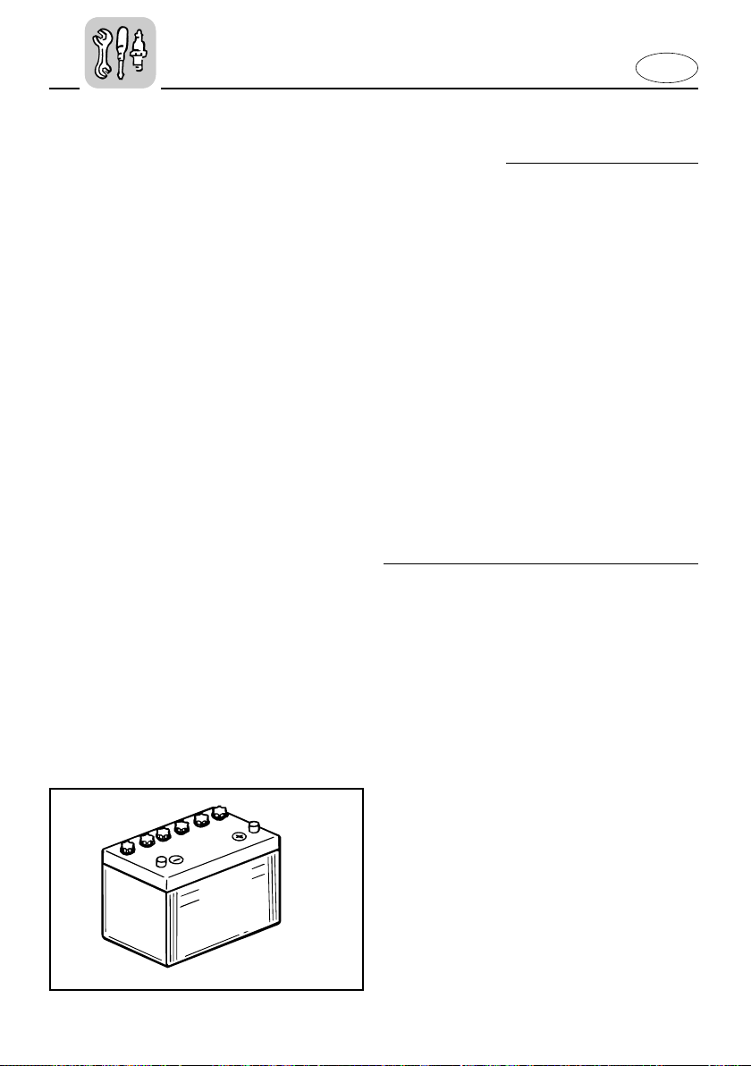
E
901015
UPPER LEVEL
LOWER LEVEL
EMU00353
Battery Care
w
Battery electrolyte is poisonous and dangerous, causing severe burns, etc. It contains sulfuric acid. Avoid contact with
skin, eyes, or clothing.
Antidote:
EXTERNAL; Flush with water.
INTERNAL; Drink large quantities of
water or milk. Follow with milk of magnesia, beaten egg, or vegetable oil. Call
physician immediately.
EYES; Flush with water for 15 minutes
and get prompt medical attention.
Batteries produce explosive gases: Keep
sparks, flame, cigarettes, etc. away.
Ventilate when charging or using in a
closed space. Always wear eye protection
when working near batteries.
KEEP OUT OF REACH OF CHILDREN.
Batteries vary among manufacturers.
Therefore the following procedures may
not always apply. Consult your battery
manufacturer’s instructions.
1) Disconnect and remove the battery
from the boat. Always disconnect the
black negative lead first to prevent the
risk of shorting.
2) Clean the battery casing and termi-
nals. Fill each cell to the upper level
with distilled water.
3) Store the battery on a level surface in
a cool, dry, well-ventilated place out
of direct sunlight.
4) Once a month, check the specific
gravity of the electrolyte and recharge
as required to prolong battery life.
4-9
Page 85
E
EMU01569
PERIODIC MAINTENANCE
w
Be sure to turn off the engine when you
perform maintenance unless otherwise
specified. If the owner is not familiar with
machine servicing, this work should be
done by a Yamaha dealer or other qualified mechanic.
Maintenance, replacement, or repair of
the emission control devices and systems
may be performed by any marine engine
repair establishment or individual. All
warranty repairs, however, including
those to the emission control system,
must be performed by an authorized
Yamaha marine dealership.
A service manual is available for purchase
through a Yamaha dealer for owners who
have the mechanical skills, tools, and
other equipment necessary to perform
maintenance not covered by this owner’s
manual.
EMU00356
REPLACEMENT PARTS
If replacement parts are necessary, use
only genuine Yamaha parts or equivalents of the same type and of equivalent
strength and materials. Any part of inferior quality may malfunction, and the
resulting loss of control could endanger
the operator and passengers.
Yamaha genuine parts and accessories
are available from a Yamaha dealer.
4-10
Page 86
E
EMU00361*
MAINTENANCE CHART
Frequency of maintenance operations may be adjusted according to the operating conditions, but the following table gives general guidelines.
The mark (●) indicates the check-ups which you may carry out yourself.
The mark (1) indicates work to be carried out by your Yamaha dealer.
Interval
Item
Spark plug
Greasing points Greasing ● 4-12
Gear oil Change ●●4-26
Fuel system Inspection ● 4-16
Fuel filter
Fuel tank Cleaning ● 4-28
Idling speed Adjustment ●●4-18
Anode
Outboard motor exterior Inspection ●● 4-34
Cooling water passages Cleaning ●● 4-6, 4-33
Propeller Inspection ●● 4-24
Timing belt Inspection 1 4-21
Battery Inspection
Power trim and tilt Inspection ●●● 4-23
Ignition timing Inspection/Adjustment 11—
Bolts and nuts Retightening 114-32
Engine oil Change ●●4-19
Oil filter Change 1 —
Valve clearance Inspection/Adjustment 11 —
Thermostat Inspection 1 —
Cleaning/Adjustment/
Replacement
Inspection/Replacement
Inspection/Replacement
Initial Every
10 hours
(1 month)
● (every
month)
50 hours
(3 months)
●●● 4-14
●●● 4-17
100 hours
(6 months)
11 4-29
200 hours
(1 year)
Refer
page
4-30
1. When operating in salt water, turbid or muddy water, the engine should be flushed with clean
water after each use.
NOTE:
If leaded gasoline is usually used, engine valves and related parts should be inspected
after every 300 hours of operation in addition to the items on the maintenance chart
above.
4-11
Page 87
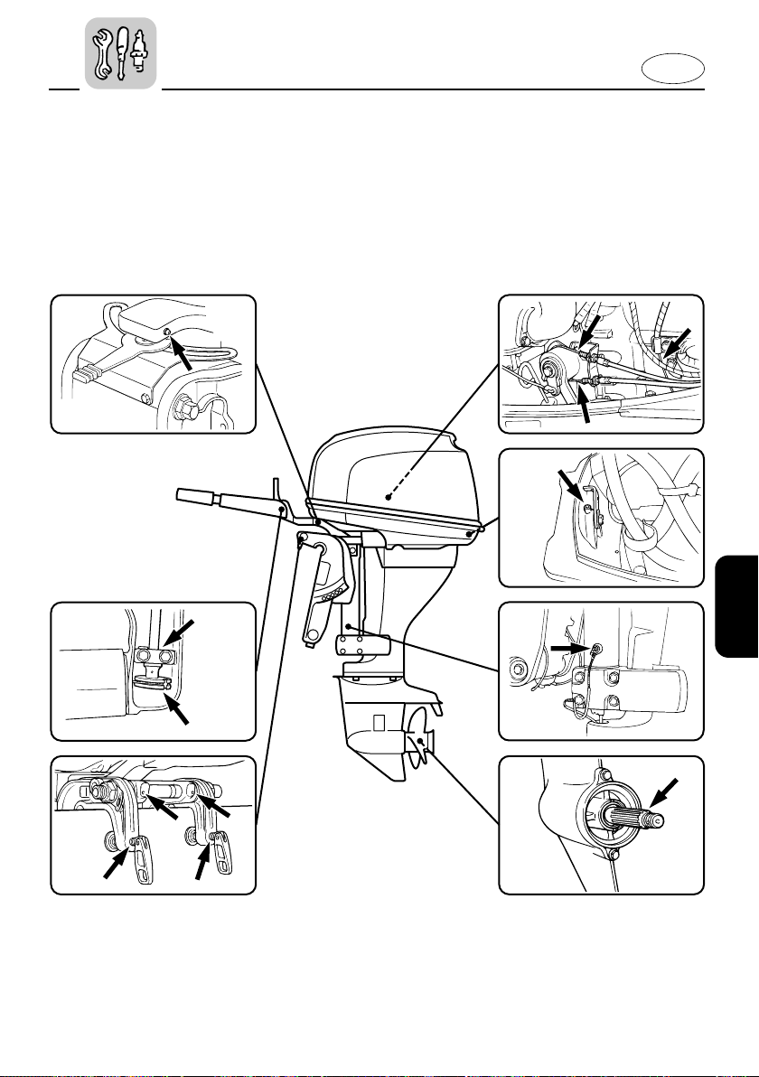
EMU00366
GREASING
Yamaha marine grease
(Water resistant grease)
E
4-12
Page 88
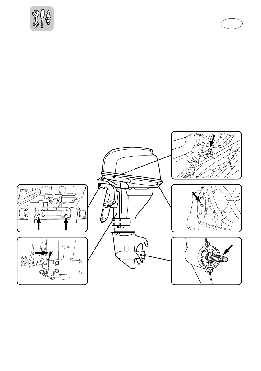
103182
EMU00366
GREASING
Yamaha marine grease
(Water resistant grease)
E
4-13
Page 89
E
EMU01202
CLEANING AND ADJUSTING SPARK
PLUG
w
When removing or installing a spark plug,
be careful not to damage the insulator. A
damaged insulator could allow external
sparks, which could lead to explosion or
fire.
The spark plug is an important engine
component and is easy to inspect. The
condition of the spark plug can indicate
something about the condition of the
engine. For example, if the center electrode porcelain is very white, this could
indicate an intake air leak or carburetion
problem in that cylinder. Do not attempt
to diagnose any problems yourself.
Instead, take the outboard motor to a
Yamaha dealer. You should periodically
remove and inspect the spark plug
because heat and deposits will cause the
spark plug to slowly break down and
erode. If electrode erosion becomes
excessive, or if carbon and other deposits
are excessive, you should replace the
spark plug with another of the correct
type.
Standard spark plug:
Refer to “SPECIFICATIONS”, page 4-1.
Before fitting the spark plug, measure the
electrode gap with a wire thickness
gauge; adjust the gap to specification if
necessary.
Spark plug gap:
Refer to “SPECIFICATIONS”, page 4-1.
4-14
Page 90
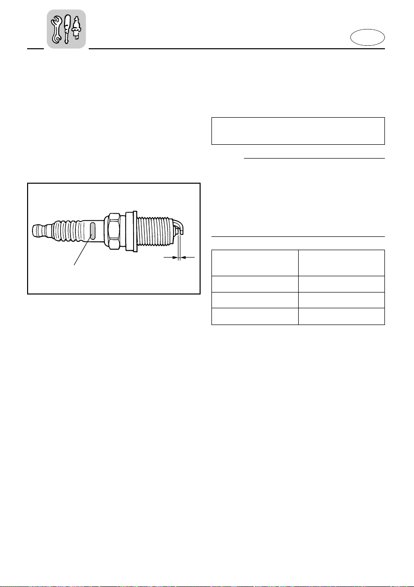
E
903033
w
q
When fitting the plug, always clean the
gasket surface and use a new gasket.
Wipe off any dirt from the threads and
screw in the spark plug to the correct
torque.
Spark plug torque:
Refer to “SPECIFICATIONS”, page 4-1.
NOTE:
If a torque-wrench is not available when
you are fitting a spark plug, a good estimate of the correct torque is 1/4 to 1/2 a
turn past finger-tight. Have the spark plug
adjusted to the correct torque as soon as
possible with a torque-wrench.
Initial of spark plug
I.D. mark
B 21 mm (13/16 in.)
C/BK 16 mm (5/8 in.)
D 18.3 mm (23/32 in.)
1 Spark plug gap
2 Spark plug I.D. mark (NGK)
Plug wrench size
4-15
Page 91
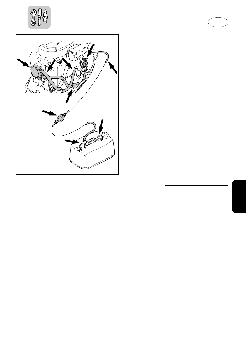
E
106055
EMU00369
CHECKING FUEL SYSTEM
w
Gasoline (petrol) and its vapors are highly
flammable and explosive. Keep away
from sparks, cigarettes, flames or other
sources of ignition.
Check the fuel line for leaks, cracks, or
malfunctions. If any problem is found, it
should be repaired immediately by
Yamaha dealer or other qualified mechanic.
Checking points
8 Fuel system parts leakage.
8 Fuel hose joint leakage.
8 Fuel hose cracks or other damage.
8 Fuel connector leakage.
w
Leaking fuel can result in fire or explosion.
8 Check for fuel leakage regularly.
8 If any fuel leakage is found, the fuel
system must be repaired by a qualified
mechanic. Improper repairs can make
the outboard unsafe to operate.
4-16
Page 92
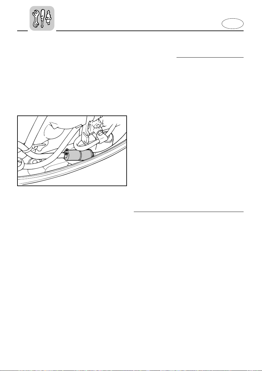
E
207053
EMU00370
INSPECTING FUEL FILTER
w
Gasoline (petrol) is highly flammable, and
its vapors are flammable and explosive.
8 If you have any question about properly
doing this procedure, consult your
Yamaha dealer.
8 Do not perform this procedure on a hot
or running engine. Allow the engine to
cool.
8 There will be fuel in the fuel filter. Keep
away from sparks, cigarettes, flames or
other sources of ignition.
8 This procedure will allow some fuel to
spill. Catch fuel in a rag. Wipe up any
spilled fuel immediately.
8 The fuel filter must be reassembled
carefully with O-ring, filter cup, and
hoses in place. Improper assembly or
replacement can result in a fuel leak,
which could result in a fire or explosion
hazard.
EMU00374
Check the fuel filter periodically.
The fuel filter is a one-piece, disposable
type. If foreign matter is found in the filter, replace it. For replacement of the fuel
filter, consult a Yamaha dealer.
4-17
Page 93
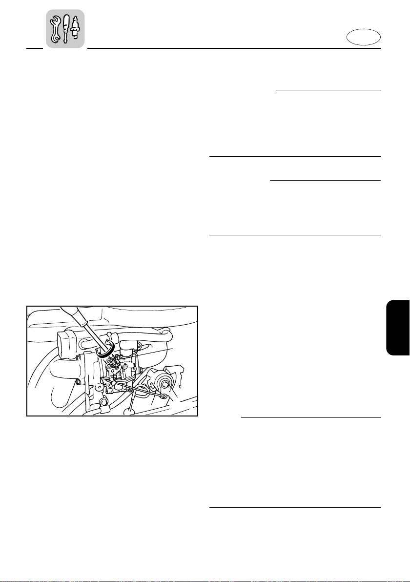
204051
q
E
EMU00991
ADJUSTING IDLING SPEED
w
8 Do not touch or remove electrical parts
when starting or during operation.
8 Keep hands, hair and clothes away
from flywheel and other rotating parts
while engine is running.
cC
This procedure must be performed while
the outboard motor is in the water. A
flushing attachment or test tank can be
used.
A diagnostic tachometer should be used
for this procedure.
1) Start the engine and allow it to warm
up fully in Neutral until it is running
smoothly. If the outboard is mounted
on a boat, be sure the boat is tightly
moored.
2) Adjust the throttle stop-screw 1 to
set the idling speed to specification
(see “SPECIFICATIONS” on page 4-1)
by turning the stop-screw clockwise
to increase the idling speed, and turning it counterclockwise to decrease
the idling speed.
NOTE:
Correct idling-speed adjustment is only
possible if the engine is fully warmed-up.
If not warmed up fully, the speed setting
will tend to be too high. If you have difficulty obtaining the specified idle, consult
a Yamaha dealer or other qualified
mechanic.
4-18
Page 94
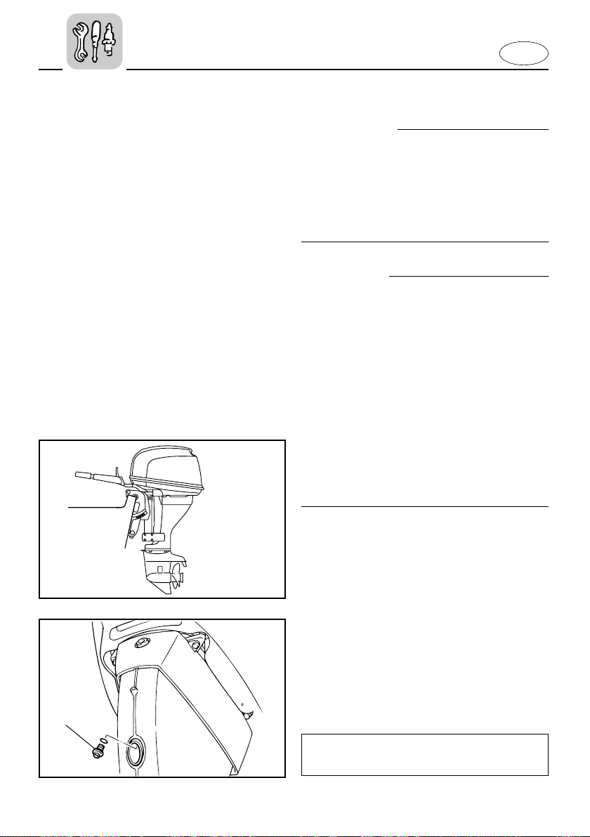
E
000912
EMU01415
CHANGING ENGINE OIL
w
8 Avoid draining the engine oil immedi-
ately after stopping the engine. The oil
is hot and should be handled with care
to avoid burns.
8 Be sure the outboard is securely fas-
tened to the transom or a stable stand.
cC
8 Change the engine oil after the first 10
hours of operation, and every 100 hours
or at 6-month intervals thereafter.
Otherwise, the engine will wear quickly.
8 Do not overfill the oil, and be sure the
engine is in an upright position (not tilted) when checking and changing the
engine oil.
8 If the oil level is above the upper level
mark, drain until the level meets the
specified capacity. Overfilling the oil
may cause leakage or damage.
q
601025
1) Put the outboard motor in an upright
position (not tilted).
2) Prepare a suitable container which
can hold a larger amount than the
engine oil capacity. Loosen and
remove the drain bolt 1 while holding the container under the drain
hole. Let the oil drain completely.
Wipe up any spilled oil immediately.
3) Put a new gasket on the drain bolt.
Apply a light coat of oil to the gasket
and reinstall the drain bolt.
Tightening torque:
Refer to “SPECIFICATIONS”, page 4-1.
4-19
Page 95
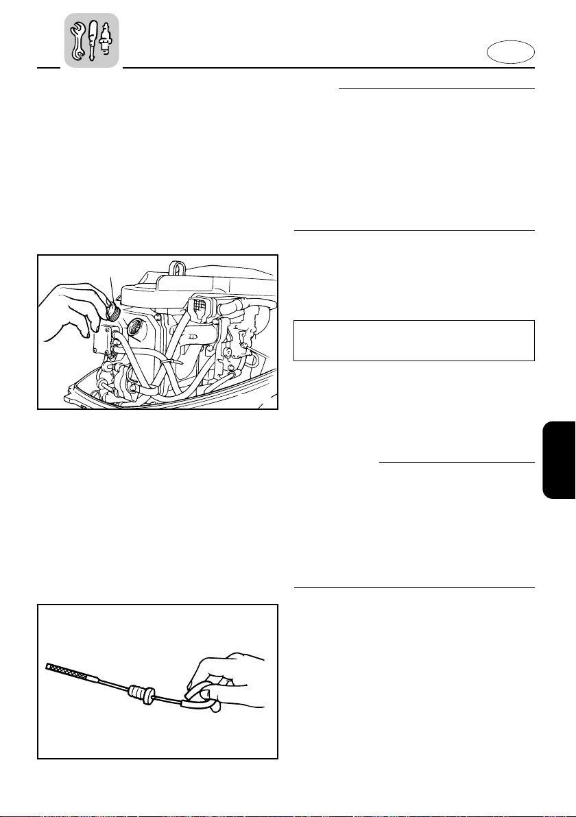
E
203025
w
NOTE:
If a torque wrench is not available when
you are installing the drain plug, finger
tighten the bolt just until the gasket
comes into contact with the surface of the
drain hole. Then tighten 1/4 - 1/2 turn.
Have the drain plug torqued to the correct
value with a torque wrench as soon as
possible.
4) Remove the oil filler cap 2. Add the
correct amount of oil through the
filler hole.
Reinstall the filler cap.
Engine oil grade/capacity:
Refer to “SPECIFICATIONS”, page 4-1.
5) Start the engine and watch to make
sure the low oil pressure warning
lamp turns off. Make sure that there
are no oil leaks.
cC
If the oil lamp does not turn off, or if
there are oil leaks, stop the engine and
find the cause. Continued operation with
a problem could cause severe engine
damage. If the problem cannot be found
and corrected, consult your Yamaha dealer.
201012
6) Turn off the engine and wait 3 minutes. Recheck the oil level using the
dipstick to be sure the level falls
between the upper and lower marks.
Fill with oil if it is below the lower
mark, or drain to the specified level if
it is above the upper mark.
7) Dispose of used oil according to local
regulations.
4-20
Page 96
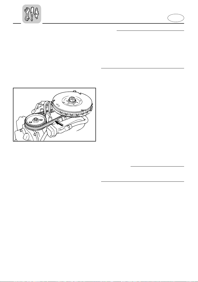
E
206013
NOTE:
8 For disposal of used oil consult your
Yamaha dealer.
8 The oil should be changed more often
when the engine is operated under
adverse conditions such as extended
trolling.
EMU00380*
CHECKING TIMING BELT
Inspect the timing-belt and replace it if
any of the following signs is observed:
8 Cracks in the back of the belt or in the
base of belt teeth.
8 Excessive wear at the roots of cogs.
8 Rubber portion swollen by oil.
8 Belt surfaces roughened.
8 Signs of wear on edges or outer surface
of belt.
8 Stretching by 10 mm (0.39 in) or more
when the belt is pushed with a finger.
cC
Consult your Yamaha dealer when replacing the timing-belt.
4-21
Page 97
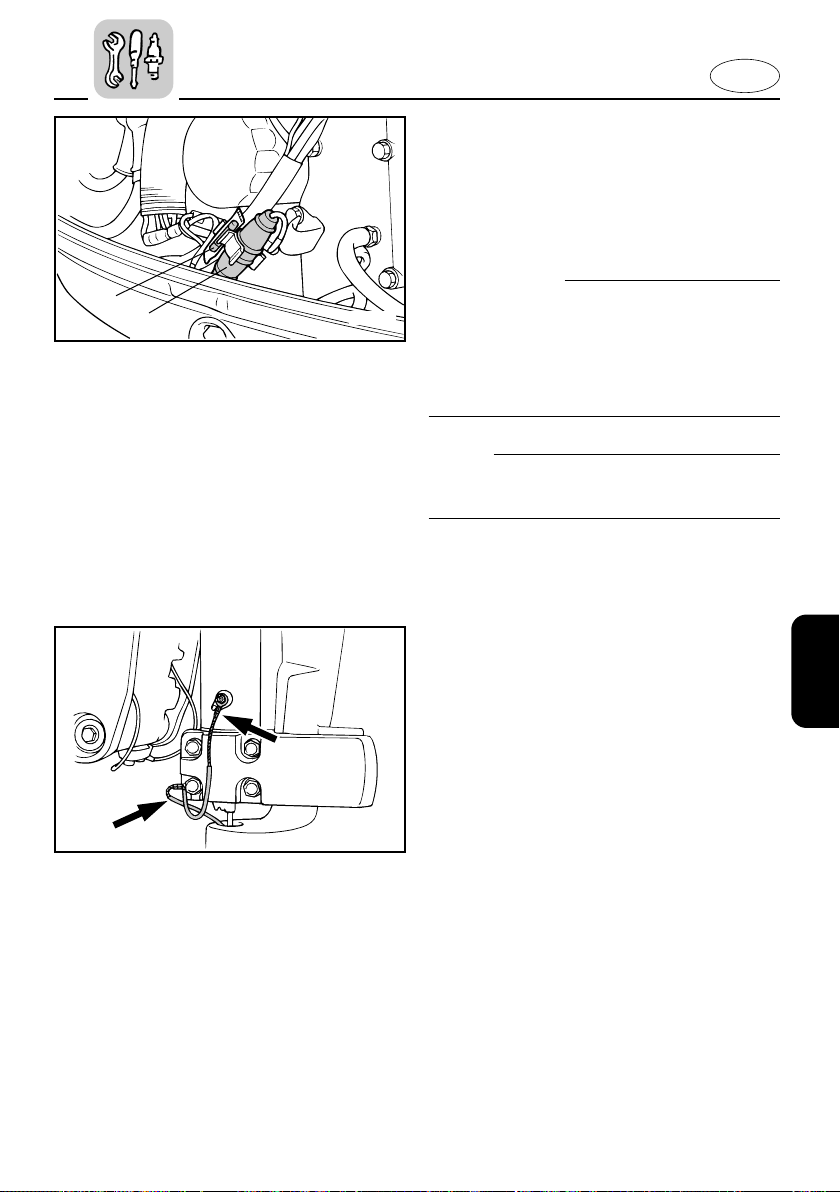
E
205044
q
w
EMU01329
REPLACING FUSE
If the fuse has blown on an Electric start
model, open the fuse holder and replace
the fuse with a new one of proper amperage.
w
Be sure to use the specified fuse. An
incorrect fuse or a piece of wire may
allow excessive current flow. This could
cause electrical system damage and a fire
hazard.
NOTE:
If the new fuse blows again immediately,
consult a Yamaha dealer.
1 Fuse holder
2 Fuse (20A)
EMU00383
CHECKING WIRING AND
CONNECTORS
1) Check that each grounding wire is
properly secured.
2) Check that each connector is engaged
securely.
413014
EMU00384
EXHAUST LEAKAGE
Start the engine and check that no
exhaust leaks from the joints between the
exhaust cover, cylinder head and crank
case.
EMU00385
WATER LEAKAGE
Start the engine and check that no water
leaks from the joints between the exhaust
cover, cylinder head and crank case.
4-22
Page 98
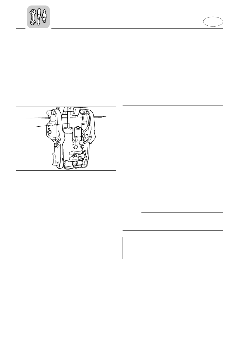
E
411034
q
EMU00992
CHECKING POWER TRIM AND TILT
SYSTEM
w
8 Never get under the lower unit while it
is tilted, even when the tilt-support
lever is locked. Severe injury could
occur if the outboard accidentally falls.
8 Make sure no one is under the out-
board before performing this test.
1) Check the power trim and tilt unit for
any sign of oil leaks.
2) Operate each of the power trim and
tilt switches on remote control and
engine bottom cowling (If equipped)
to check that all switches work.
3) Tilt up the motor and check that the
trim and tilt rod 1 is pushed out completely.
4) Check that the trim and tilt rod is free
of corrosion or other flaws.
5) Operate the motor to trim and tilt
down. Check that the trim and tilt rod
operates smoothly.
NOTE:
If any operation is abnormal, consult a
Yamaha dealer.
Recommended fluid;
Yamaha power trim & tilt fluid or ATF
(DEXRON-II)
4-23
Page 99
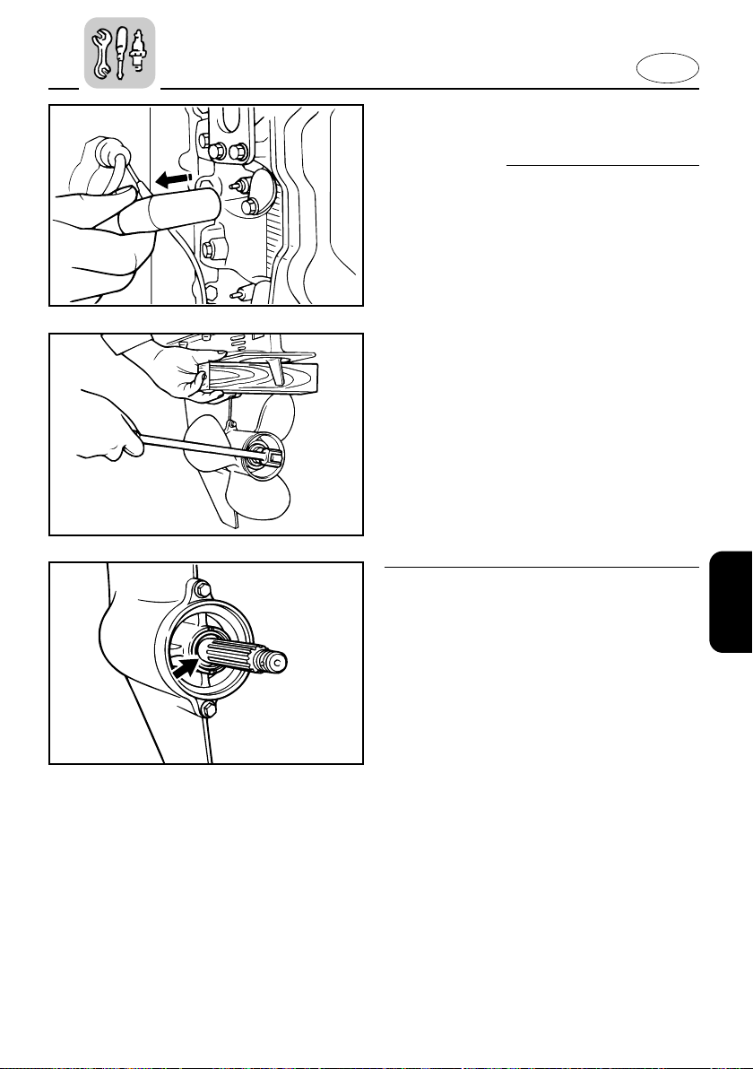
210011
602051
E
EMU00388
CHECKING PROPELLER
w
You could be seriously injured if the
engine accidentally starts while you are
near the propeller.
8 Before inspecting, removing or
installing the propeller, remove the
spark plug caps from the spark plugs.
Also, put the shift control in Neutral,
put the main switch in the “OFF” position and remove the key, and remove
the lanyard from the engine stop
switch. Turn off the battery cut-off
switch if your boat has one.
8 Do not use your hand to hold the pro-
peller when loosening or tightening the
propeller nut. Put a wood block
between the cavitation plate and the
propeller to prevent the propeller from
turning.
602054
EMU00390
Propeller Checking Point
8 Check each of the propeller blades for
wear, erosion from cavitation or ventilation, or other damage.
8 Check the splines for wear and damage.
8 Check for fish line winding around the
propeller shaft.
8 Check the propeller shaft oil seal for
damage.
4-24
Page 100
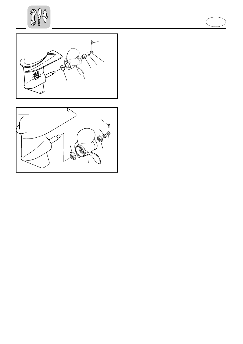
602073
q
w
e
r
t
y
FT25
6
5
4
1
2
3
602045*
E
EMU00976
Removing the Propeller
1) Straighten the cotter-pin 1 and pull it
out using a pair of pliers.
2) Remove the propeller nut 2, washer
3 and spacer 4.
3) Remove the propeller 5 and thrust
washer 6
EMU00397
Installing the Propeller
cC
8 Be sure to install the thrust washer
before installing propeller, otherwise,
lower case and propeller boss may be
damaged.
8 Be sure to use a new cotter pin and
bend the ends over securely.
Otherwise, the propeller could come off
during operation and be lost.
1) Apply Yamaha Marine grease or
Corrosion resistant grease to the propeller-shaft.
2) Install the thrust washer and propeller
on the propeller-shaft.
3) Install the spacer and washer. Tighten
the propeller nut to the specified
torque.
4-25
 Loading...