


 Loading...
SERVICE MANUAL


 ECF
ECF
This document is printed on chlorine free (ECF) paper.
• OPTION |
|
RK5014 RACK MOUNT KIT |
|
|
|
■ CONTENTS |
|
SPECIFICATIONS .................................................................. |
3/5 |
DIMENSIONS .............................................................................. |
7 |
PANEL LAYOUT ......................................................... |
8 |
CIRCUIT BOARD LAYOUT .................................. |
12 |
WIRING DIAGRAM ............................................................. |
13 |
OVERALL ASSEMBLY WIRING DRAWING ................... |
14 |
DISASSEMBLY PROCEDURES ............................................. |
27 |
LSI PIN DESCRIPTIONLSI .................................................. |
37 |
IC BLOCK DIAGRAMIC ...................................................... |
40 |
CIRCUIT BOARDS ........................................................... |
42 |
TEST PROGRAM ................................................ |
67/73 |
INSPECTIONS .......................................................................... |
79/91 |
PA UNIT INSPECTIONPA ...................................... |
103/106 |
PS CIRCUIT BOARD REPAIR GUIDE |
|
PS .............................................................. |
110/120 |
PARTS LIST |
|
IC & DIODE FIGURES |
|
BLOCK DIAGRAM |
|
CIRCUIT DIAGRAM |
|
PA 011824
HAMAMATSU, JAPAN
Copyright (c) Yamaha Corporation. All rights reserved.


 06.07
06.07

EMX5016CF
IMPORTANT NOTICE
This manual has been provided for the use of authorized Yamaha Retailers and their service personnel. It has been assumed that basic service procedures inherent to the industry, and more specifically Yamaha Products, are already known and understood by the users, and have therefore not been restated.
WARNING: Failure to follow appropriate service and safety procedures when servicing this product may result in personal injury, destruction of expensive components and failure of the product to perform as specified. For these reasons, we advise all Yamaha product owners that all service required should be performed by an authorized Yamaha Retailer or the appointed service representative.
IMPORTANT: This presentation or sale of this manual to any individual or firm does not constitute authorization, certification, recognition of any applicable technical capabilities, or establish a principal-agent relationship of any form.
The data provided is believed to be accurate and applicable to the unit(s) indicated on the cover. The research engineering, and service departments of Yamaha are continually striving to improve Yamaha products. Modifications are, therefore, inevitable and changes in specification are subject to change without notice or obligation to retrofit. Should any discrepancy appear to exist, please contact the distributor’s Service Division.
WARNING: Static discharges can destroy expensive components. Discharge any static electricity your body may have accumulated by grounding yourself to the ground bus in the unit (heavy gauge black wires connect to this bus).
IMPORTANT: Turn the unit OFF during disassembly and parts replacement. Recheck all work before you apply power to the unit.
WARNING: CHEMICAL CONTENT NOTICE!
The solder used in the production of this product contains LEAD. In addition, other electrical/electronic and/or plastic (Where applicable) components may also contain traces of chemicals found by the California Health and Welfare Agency (and possibly other entities) to cause cancer and/or birth defects or other reproductive harm.
DO NOT PLACE SOLDER, ELECTRICAL/ELECTRONIC OR PLASTIC COMPONENTS IN YOUR MOUTH FOR ANY REASON WHAT SO EVER!
Avoid prolonged, unprotected contact between solder and your skin! When soldering, do not inhale solder fumes or expose eyes to solder/flux vapor!
If you come in contact with solder or components located inside the enclosure of this product, wash your hands before handling food.
|
|
IMPORTANT NOTICE FOR THE UNITED KINGDOM |
|
|
Connecting the Plug and Cord |
WARNING: |
THIS APPARATUS MUST BE EARTHED |
|
IMPORTANT. |
The wires in this mains lead are coloured in accordance with the following code: |
|
|
GREEN-AND-YELLOW: EARTH |
|
|
BLUE: |
NEUTRAL |
|
BROWN: |
LIVE |
As the colours of the wires in the mains lead of this apparatus may not correspond with the coloured markings identifying the terminals in your plug, proceed as follows:
The wire which is coloured GREEN and YELLOW must be connected to the terminal in the plug which is marked by the letter E or by the safety earth symbol  or colored GREEN or colored GREEN and YELLOW.
The wire which is coloured BLUE must be connected to the terminal which is marked with the letter N or coloured BLACK.
The wire which is coloured BROWN must be connected to the terminal which is marked with the letter L or coloured RED.
■ WARNING
Components having special characteristics are marked  and must be replaced with parts having specification equal to those originally installed.

2

EMX5016CF
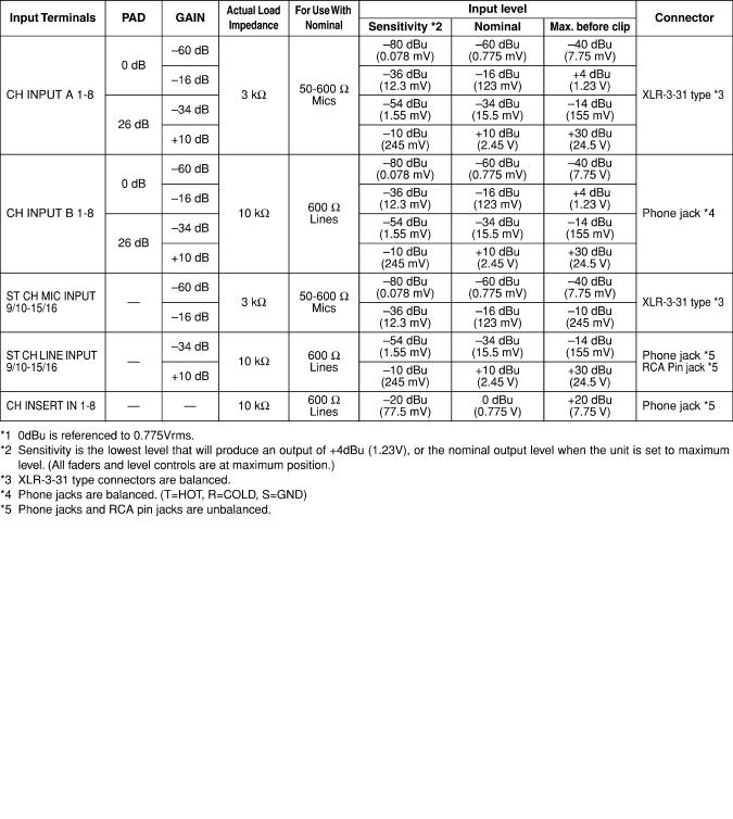
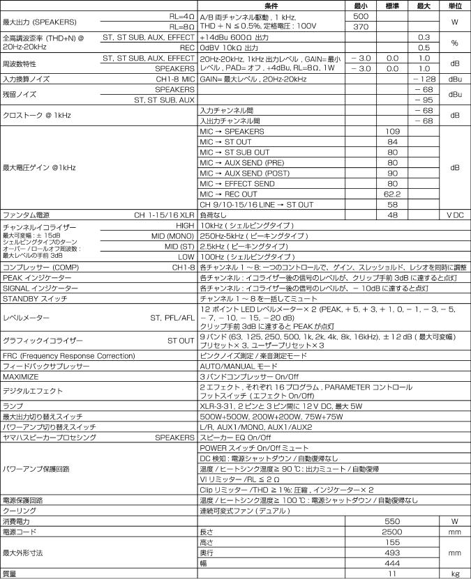
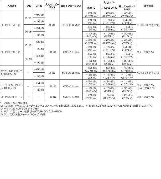
■ SPECIFICATIONS
•General Specifications
*All level controls are nominal, when measured. Output impedance of signal generator: 150Ω
3
EMX5016CF
• Input Characteristics
• Output Characteristics
4
EMX5016CF
■
* 150Ω
5
EMX5016CF
6
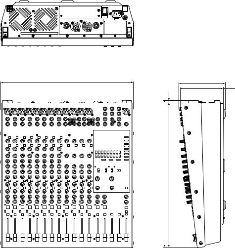
■ DIMENSIONS
444 (440 excluding screw heads)
444 440 |
8 |
|
|
493 |
485 |
EMX5016CF
155
6
145
Unit: mm
mm
7
EMX5016CF
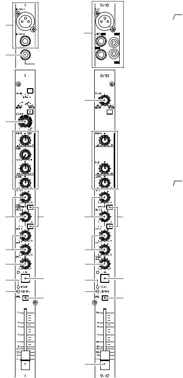
■ PANEL LAYOUT
• Controls on Each Channel
Channels |
|
1 to 8 |
1 8 |
(Monaural) |
|
1
3

 4 5
4 5


 6
6
7
Channels |
|
9/10 to 15/16 |
9/10 15/16 |
(Stereo) |
|
2 |
5

 6
6
8 |
8 |
9 |
0 |
A |
|
B |
|
D |
C |
E |
|
|
F |
9 |
0 |
A |
|
B |
|
D |
C |
E |
|
|
F |
1 INPUT A and INPUT B Jacks (Channels 1 to 8) 2 LINE/MIC Jacks (Channels 9/10 to 15/16)
3 INSERT I/O Jack (Channels 1 to 8)
4 [26 dB] Switch (Channels 1 to 8)
5 GAIN Control
6 80 (High Pass Filter) Switch
7 COMP knob (Channels 1 to 8)
8 Equalizer (HIGH, MID, and LOW)
9 AUX 1/2 Knobs (PRE/POST)
0 PRE Switch A EFF 1/2 Knobs
BPAN Control (Channels 1 to 8); BAL Control (Channels 9/10 to 15/16)
C ON Switch
D PEAK Indicator
E SIGNAL Indicator
F PFL (Pre-Fader Listen) Switch
G Channel Fader
1 INPUTA/B 1 8
2 LINE/MIC 9/10 15/16 3 INSERT I/O 1 8
4 26dB 1 8 5 GAIN
6 80
7 COMP 1 8
8 EQ HIGH MID LOW 9 AUX 1/2 PRE/POST
0 PRE
A EFF 1/2
B PAN 1 8 /BAL
9/10 15/16
C ON
D PEAK
E SIGNAL
F PFL Pre-Fader Listen
G
G G
G
8
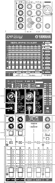
• Digital Effects Section
H
I |
I |
J |
|
|
J |
K |
K |
L |
L |
M |
|
|
M |
N |
N |
EMX5016CF
HSEND Jacks (EFF 1, EFF 2 / AUX 1, AUX 2) I PROGRAM Dials
J PARAMETER Knobs K AUX 1/2 Knobs
L EFF 1/2 ON Switches/Indicators M PFL (Pre-Fader Listen) Switches N EFF 1/2 RTN Faders
HSEND EFF 1 EFF 2 / AUX 1 AUX 2 I PROGRAM
J PARAMETER K AUX 1/2
L EFF 1/2 ON /
M PFL Pre-Fader Listen N EFF 1/2 RTN
9
EMX5016CF
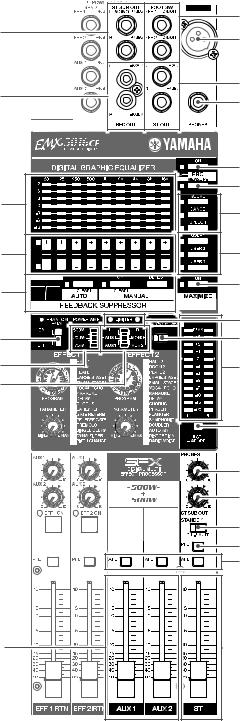
• Master Section
|
Q |
O |
T |
|
|
|
R |
P |
S |
|
|
|
W |
|
X |
U |
Y |
|
|
V |
Z |
[ |
\ |
|
|
|
] |
c |
b |
_ |
d |
a |
|
|
e |
|
f |
|
g |
|
h |
|
i |
|
j |
k |
l |
O ST SUB OUT Jacks
P REC OUT Jacks
Q EFF 1/2 ON/OFF Jacks
R ST OUT Jacks
S PHONES Jack
T LAMP Jack
U GEQ (Graphic Equalizer) display
V GEQ +/- Switches
W GEQ ON Switch
XFRC MEASURE/CORRECT switch (MEASURE mode, CORRECT mode)
Y VOCAL, DANCE, SPEECH Switches
Z USER 1, USER 2, USER 3 Switches
[ Feedback Suppressor (AUTO mode, MANUAL mode) \ MAXIMIZE ON switch
] LIMITER Indicators
^ Maximum Output Switch a POWER AMP Switch b YS Processing Switch
c PHANTOM Switch and Indicator d LEVEL Meters
e ST/AFL-PFL Switch f PHONES Control
g ST SUB OUT Control h STANDBY Switch
i PFL (Pre-Fader Listen) Switch
j AFL (After-Fader Listen) Switches k AUX 1 and AUX 2 Faders
l ST Master Fader
O ST SUB OUT
P REC OUT
Q EFF 1/2 ON/OFF R ST OUT
S PHONES
T LAMP
U GEQ
V GEQ /
W GEQ ON
XFRC MEASURE/AUTO MEASURE AUTO
Y VOCAL DANCE SPEECH
Z USER 1 USER 2 USER 3
[FEEDBACK SUPPRESSOR / AUTO MANUAL
\ MAXIMIZE ON
] LIMITER
^
a POWER AMP b YS Processing
c PHANTOM / d LEVEL
e ST/AFL-PFL f PHONES
g ST SUB OUT h STANDBY
i PFL Pre-Fader Listen j AFL After-Fader Listen k AUX 1/2
l ST
10
• Rear Panel
p o n |
m |
EMX5016CF
mSPEAKERS jacks n POWER Switch o AC IN Connector p Ground Screw
mSPEAKERS n POWER o AC IN
p GND
11
EMX5016CF
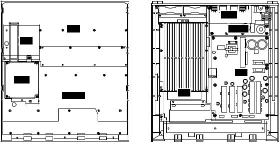
■ CIRCUIT BOARD LAYOUT
Rear
JK |
PN |
DSP
MAIN
PA |
OUT |
INLET |
PS |
|
Front |
Panel Assembly |
|
Bottom Assembly |
|
Ass'y |
Ass'y |
12
|
|
|
|
|
|
|
|
|
|
|
|
|
|
FAN2 |
|
FAN1 |
|
|
|
|
|
|
|
|
|
|
|
CN904 |
CN100 |
CN101 |
PN |
|
|
|
|
|
|
|
|
|
|
|
|
|
|
|
|
|
|
|
|
|
|
|
|
|
|||
|
|
|
|
|
|
|
|
(10P) |
(18P) |
(2P) |
|
|
|
|
|
|
|
|
|
|
|
|
JK |
|
|
|
|
|
|
|
|
|
|
|
|
|
|
|
|
|
|
|
|
|
|
|
|
|
|
|
|
|
|
|
|
18 |
|
|
|
|
|
|
|
|
|
|
|
|
|
W305 CN301 CN303 |
OUT |
W303 W304 |
|
INLET |
|||||
|
|
|
|
|
|
|
|
|
|
|
|
|
|||||||
|
|
|
|
|
|
|
|
|
|
CN302 |
|
|
|
|
|||||
CN101 |
CN102 |
CN103 |
CN104 |
CN105 |
CN106 |
CN107 |
CN108 |
CN109 |
|
BLACK |
|
|
|
|
|
|
|
|
|
|
|
|
|
|
|
|
|
|
|
||||||||||
(9P) |
(9P) |
(9P) |
(9P) |
(9P) |
(9P) |
(9P) |
(9P) |
(5P) |
|
|
|
|
|
|
|
BROWN 16 |
17 GRAY |
|
|
|
|
|
|
|
|
|
|
|
7 |
|
|
|
|
|
|
|
|||
|
|
|
|
|
|
|
|
|
|
|
|
|
|
|
|
|
|
|
|
CN101 |
CN102 |
CN103 |
CN104 |
CN105 |
CN106 |
CN107 |
CN108 |
CN109 |
|
|
|
|
|
|
|
CN404 (2P) |
|
|
|
(9P) |
(9P) |
(9P) |
(9P) |
(9P) |
(9P) |
(9P) |
(9P) |
(5P) |
|
PA |
|
|
|
|
|
|
|
PS |
|
|
9 |
10 |
8 |
|
CN410 |
CN402 |
|
||||||||||||
|
|
|
|
|
|
|
|
|
|
|
|
|
|
||||||
|
|
|
|
|
|
|
|
|
|
|
|
|
|
|
|
||||
|
|
|
|
|
|
|
|
|
|
VIOLET |
|
|
YELLOW |
CN905 (2P) |
|
|
|
||
|
|
|
|
|
|
|
CN100 (18P) |
|
|
|
|
|
|
|
11 BLACK |
|
|
||
|
|
|
|
|
|
|
|
|
|
|
|
|
W105 |
13 WHITE |
|
|
|
||
|
|
|
|
|
|
|
|
|
|
W102 |
|
|
|
|
|
|
|||
|
|
|
|
|
|
|
|
|
|
|
|
|
|
|
|
|
|
||
|
|
|
|
CN801 |
|
|
|
|
CN101 |
|
|
|
|
W107 |
|
|
15 |
BLUE |
|
|
|
|
|
|
|
|
|
(14P) |
|
|
|
|
|
|
|
|
|
||
|
|
|
|
|
(20P) |
|
|
CN800 |
|
|
|
|
|
1 |
|
CN902 |
|
|
|
|
|
|
|
|
|
|
|
(20P) |
|
|
|
|
|
|
(14P) |
|
|
|
|
|
|
|
MAIN |
|
|
DSP |
|
|
|
|
|
BLACK |
W103 |
CN405 |
CN406 |
||||
|
|
|
|
|
|
|
|
|
|
|
|
CN409 |
CN407 |
CN408 |
|||||
|
|
|
|
|
|
|
|
|
|
|
|
|
|
|
|
||||
|
|
|
|
|
|
|
|
|
|
|
W101 |
|
|
W104 |
12 RED |
|
|
|
|
|
|
|
|
|
CN906 (4P) |
|
|
|
|
|
|
|
|
W106 |
14 ORANGE |
|
|
||
|
|
|
|
|
|
|
|
|
|
|
|
|
|
CN906 |
|
|
|
||
|
|
|
|
|
|
|
|
|
|
|
3 |
|
|
|
|
|
|
|
|
|
|
|
|
|
|
|
|
|
|
|
|
|
|
|
(4P) |
|
|
|
|
|
|
|
|
|
CN903 (9P) |
|
|
|
|
|
|
|
|
|
|
|
|
||
|
|
|
|
|
|
|
|
6 |
|
|
|
|
|
|
|
|
|
||
|
|
|
|
|
CN901 (8P) |
|
|
|
|
2 |
|
|
|
|
CN901(8P) |
CN903 (9P) |
|||
|
|
|
|
|
|
|
|
|
|
|
|
|
|
||||||
|
|
|
|
|
|
|
|
|
|
|
|
|
|
|
|
CN904 (10P) |
|
CN907 (2P) |
|
indicates that connectors are connected directly to circuit board. |
|
|
|
|
4 |
|
|
|
|
|
|
|
|||||||
|
|
|
|
|
|
|
|
|
|
|
|
|
|||||||
|
|
|
|
|
|
|
|
|
|
|
|
|
|||||||
|
|
|
|
|
|
|
|
|
|
|
|
|
|
|
5 |
|
|
|
|
No. |
|
Part No. |
|
Assembly Name |
|
Connection |
|
Remarks |
|
Location |
No. |
|
Part No. |
|
Assembly Name |
|
Connection |
||
|
|
|
|
|
|
|
|
||||||||||||
|
|
|
|
|
|
|
|
|
|
|
|
|
|
|
|||||
|
|
|
|
|
|
|
|
|
|
|
|
|
|
|
|
|
|
|
|
|
|
WG234700 |
|
|
|
|
|
|
|
|
|
|
|
|
|
|
|
|
|
1 |
|
|
Jumper Wire |
|
PA-CN101 <-> PS-CN902 |
|
14P-260 |
|
260 |
0 |
|
WG094600 |
|
Connector Assembly B&C |
|
PA-W103 <-> OUT-CN303 |
|||
2 |
|
WE325100 |
|
Connector Assembly |
PH |
|
JK-CN904 <-> PS-CN904 |
|
10P-650 |
|
430 |
A |
|
WG094100 |
|
Connector Assembly B&C |
|
|
OUT-W305 <-> PS-CN407 |
3 |
|
WG456800 |
|
Connector Assembly |
SIG |
|
MAIN-CN906 <-> PS-CN906 |
|
SIG |
|
440 |
B |
|
WG093600 |
|
Connector Assembly B&C |
|
|
PA-W104 <-> PS-CN405 |
4 |
|
WE321500 |
|
Connector Assembly |
PH |
|
MAIN-CN903 <-> PS-CN903 |
|
9P-350 |
|
460 |
C |
|
WG094000 |
|
Connector Assembly B&C |
|
|
PA-W105 <-> PS-CN409 |
5 |
|
WE318600 |
|
Connector Assembly |
PH |
|
MAIN-CN901 <-> PS-CN901 |
|
8P-400 |
|
450 |
D |
|
WG093700 |
|
Connector Assembly B&C |
|
|
PA-W106 <-> PS-CN406 |
6 |
|
WE301000 |
|
Connector Assembly |
PH |
|
PN-CN101 <-> PS-CN904 |
|
2P-600 |
|
465 |
E |
|
WG093800 |
|
Connector Assembly B&C |
|
|
PA-W107 <-> PS-CN408 |
7 |
|
WH292600 |
|
Flexible Flat Cable |
FFC |
|
PN-CN100 <-> DSP-CN100 |
|
18P-180 |
|
490 |
F |
|
WG094200 |
|
Connector Assembly B&C |
|
|
INLET-W303 <-> PS CN410 |
8 |
|
WG094500 |
|
Connector Assembly B&C |
|
|
PA-W101 <-> OUT-CN302 |
|
Yellow |
|
W101 |
G |
|
WG094300 |
|
Connector Assembly B&C |
|
|
INLET-W304 <-> PS-CN402 |
9 |
|
WG094400 |
|
Connector Assembly B&C |
|
|
PA-W102 <-> OUT-CN301 |
|
Violet |
|
W102 |
H |
|
WG094900 |
|
Connector Assembly |
EARTH Ass’y |
|
INLET-GND |
13
Remarks |
Location |
|
|
|
|
Black |
W103 |
Black |
W305 |
Red |
W104 |
White |
W105 |
Orange |
W106 |
Blue |
W107 |
Brown |
W303 |
Gray |
W304 |
Green/Yellow |
|
|
|
DIAGRAM WIRING ■
EMX5016CF
EMX5016CF
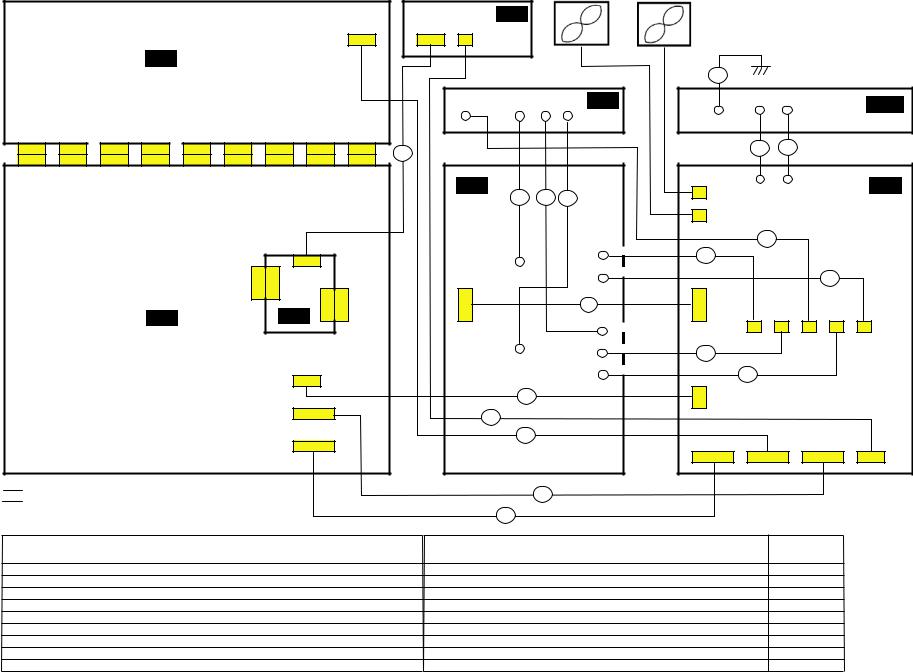
■ OVERALL ASSEMBLY WIRING DRAWING
* The number surrounded by circle shows a location of parts list.
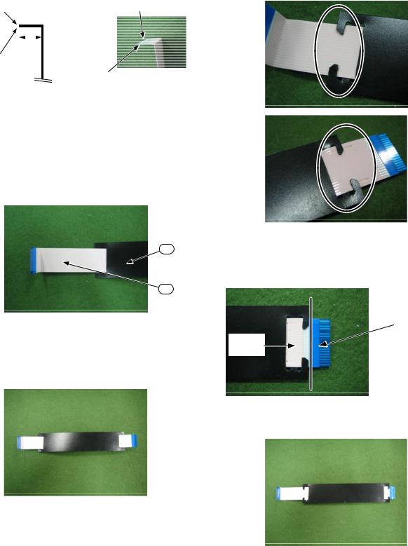
1.FFC CableFFC
The FFC cable [490] is processed as shown in the figure below beforehand.
FFC 490
|
|
|
|
Terminal side |
Terminal side |
|
|
||
|
|
|
||
|
|
|
11 |
|
|
|
|
|
|
|
|
|
|
|
|
|
|
|
Only one side |
|
|
|
|
|
Protection plate
Protection plate
The FFC cable cover [495] is installed in the FFC cable [490].
FFC 490 FFC 495
a.The FFC cable is passed through the hole of the FFC cable cover as shown in the figure below.
FFC FFC
495
490
b.The FFC cable is passed through the hole that is on the opposite side of the above-mentioned insertion entrance.
FFC
c.The fingernail in the FFC cable cover is hung on the FFC cable. (two places)
FFC FFC2
d.The edge side in the FFC cable cover is moved to protection plate of the FFC cable.
FFC FFC
Protection plate
Slide
e. Completed figure
14
EMX5016CF
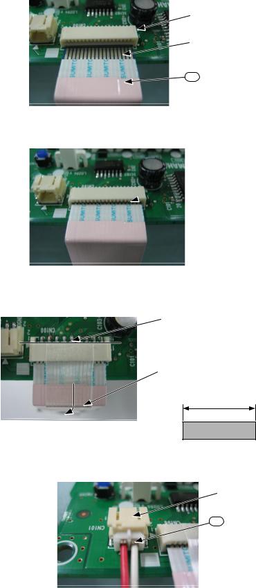
2.PN Circuit Board [480]PN 480
1. The FFC cable [490] is inserted in connector CN100.
FFC 490 CN100
* Make the terminal the upper surface and insert the wire harness.
CN100
The terminal in the wire harness is upward.
490
The bent terminal side is inserted.
It was inserted.

2. The adhesive tape [497] is pasted so that the FFC cable [490] should not come off connector CN100.
FFC 490 CN100 497
It begins to paste it from the edge side of connector CN100.
CN100
A remaining amount is pasted along the FFC cable [490].
FFC 490
50
3. The wire harness [465] is inserted in connector CN101.
465 CN101
CN101
465
15
EMX5016CF
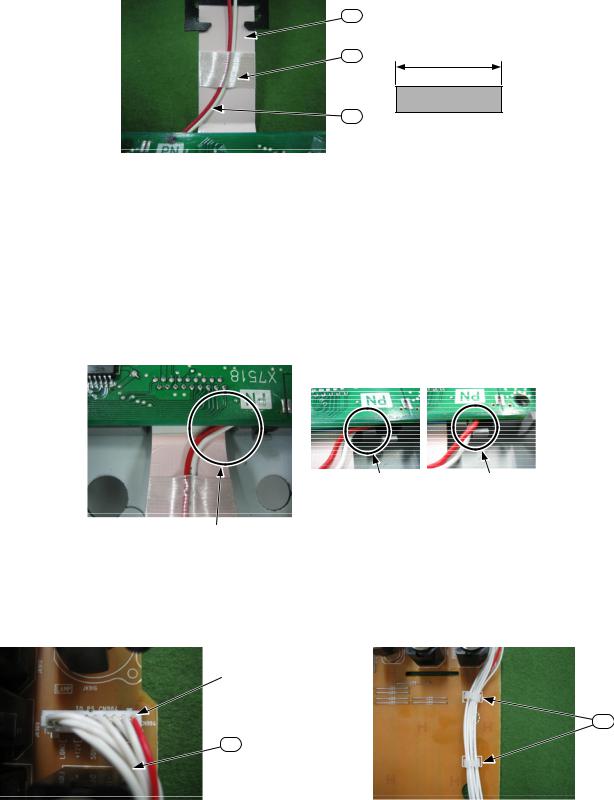
4.The wire harness [465] is fixed to the FFC cable [490] with the adhesive tape [497]. A remaining amount is wrapped around the FFC cable [490].
FFC 490 465 497 FFC 490
490
497 |
50 |
|
465
5. Escastion GEQ [470] is installed in a top cover [520].
GEQ 470 520
6. The PN circuit board [480] is installed in escastion GEQ [470].
GEQ 470 PN 480
Attention when PN circuit board is installed in escastion
GEQ 470 PN
Prevent the wire harness [465] being placed between escastion and the PN circuit board, or prevent the wire harness from going out of other holes.
465 PN
NG NG
OK
3. JK Circuit BoardJK
1. The wire harness [430] is inserted in connector CN904. |
2. The wire harness [430] is fixed by the mini-clamp [420]. |
430 CN904 |
430 420 |
CN904
420
430
16
EMX5016CF
* Fix the wire harness [430] so as not to overflow the circuit board’s edge.
430
Do not overflow the circuit board.
It fixes carefully by the mini-clamp so that the wire harness [430] is not placed for JK circuit board and a top cover.
JK 430
3. Wire harness [430] is passed through the hole.
430
Pass through the hole.
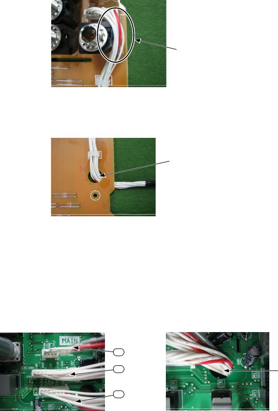
4.MAIN Circuit Board MAIN
1.The wire harness [440] is inserted in connector CN906.
440 CN906
The wire harness [460] is inserted in connector CN903.
460 CN903
The wire harness [450] is inserted in connector CN901.
450 CN901
440
460
450
2.Three wire harnesses [440, 450, 460] are passed through the hole on the side of the connector.
3 440 450 460
The connector is vertically set up and passed through the hole.
Pass through the hole.
17
EMX5016CF
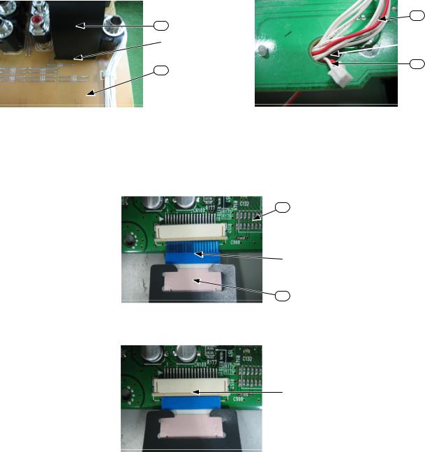
5.Panel Assembly Ass’y
MAIN circuit board and JK circuit board is mounted on a top cover. However, note the following points.
MAIN JK
* The FFC cable [490] must pass the slit in the JK circuit board [370].
FFC 490 JK 370
Pass the wire harness [465] through the same hole as the wire harness [430].
465 430
490
Pass through the hole.
370
1. Shield DSP [570] is mounted.
DSP 570
2. The FFC cable [490] is inserted in CN100 of the DSP circuit board [590].
FFC 490 DSP 590 CN100
430
Pass through the hole.

465
590
 CN100
CN100
The terminal protection plate (blue) is upturned and inserted.
490
Before insert
Confirm the locked thing.
After insert
18
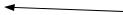
3.The DSP circuit board [590] is mounted on the MAIN circuit board.
MAIN DSP 590
590
4.When shield MIX [620] was mounted, wire harness [430, 465] is passed through a near hole.
MIX 620 430 465
Pass through the hole.
430
465
5.When shield MIX [620] was mounted, wire harness [440, 450, 460] is passed through a near hole.
MIX 620 440 450 460
Pass through the hole.
440 450 460
EMX5016CF
6. Wire harness is fixed by the wire harness clamp.
The wire harness clamp in figure fixes only the wire harness [430, 465].
430 465
All wire harness is fixed with wire saddle [670].
670
Completed figure
19
EMX5016CF
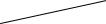
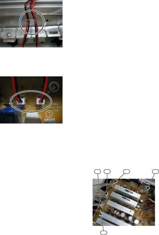
6.Bottom Assembly Ass’y
A black, purple, yellow wire is bundled and it twists it four times.
4
A red, orange, white, blue wire is bundled and it twists it two times.
2
All wire are bundled with tai [310].
310
260 It inserts it so that the first of the wire
(red line) may become one pin of the connector.
1 1
After the above-mentioned end of work, the PA unit is installed in the bottom cover unit.
PA
20
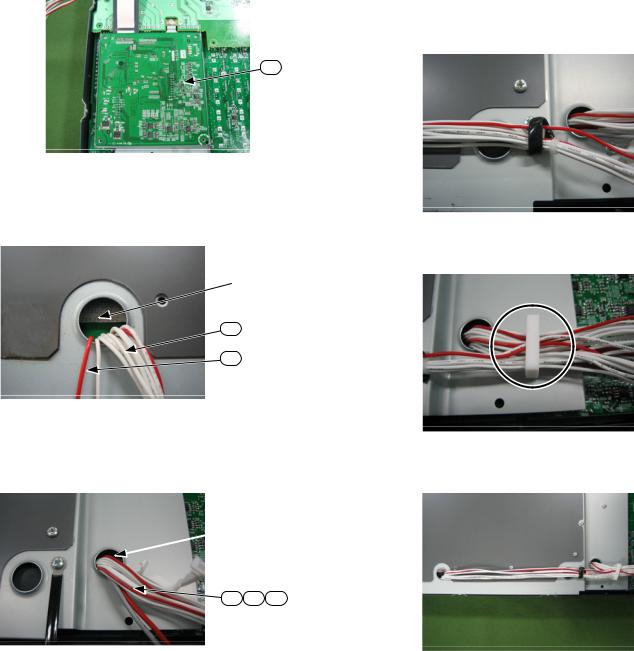
EMX5016CF
• Data line filter [150] installation 150
The data line filter is installed as follows.
1 |
|
2 |
|
|
|
The wire rolls the hole of the data line |
160 |
|
|
filter twice. |
|
|
|
2 |
|
3
Safety earth installation place: Used Screw [170]
170
The data line filter is installed as follows. (U destination)
1
The wire rolls the hole of the data line filter once.
2
160
The data line filter is fixed at the angle shown in figure.
21
EMX5016CF
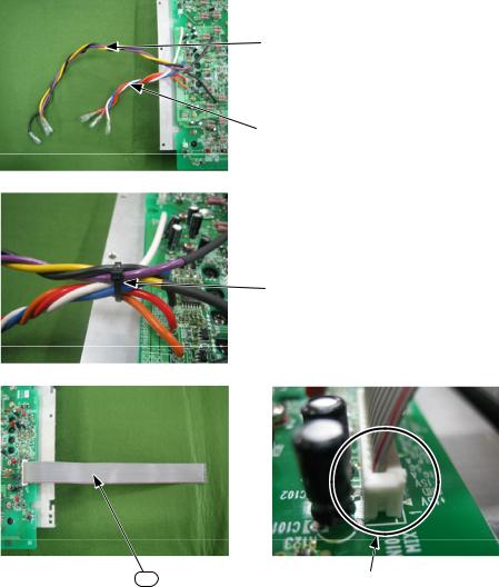
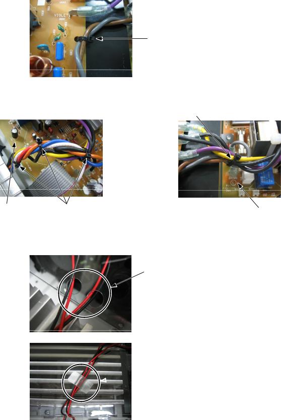
• Between PA unit – PS circuit board PA PS
It inserts it so that the first of the wire (red line) may become one pin of the connector.
1 1
Expansion
The color name of the circuit board is matched to the color of the wire harness, and it inserts it in each
faston terminal.
ファストン端子に挿入する
Color of wire: Blue → Circuit board display: BLUE
→ Blue
Color of wire: Orange → Circuit board display: ORANGE
→ ORANGE
Color of wire: Red → Circuit board display: RED
→ RED
Color of wire: White → Circuit board display: WHITE
→ WHITE
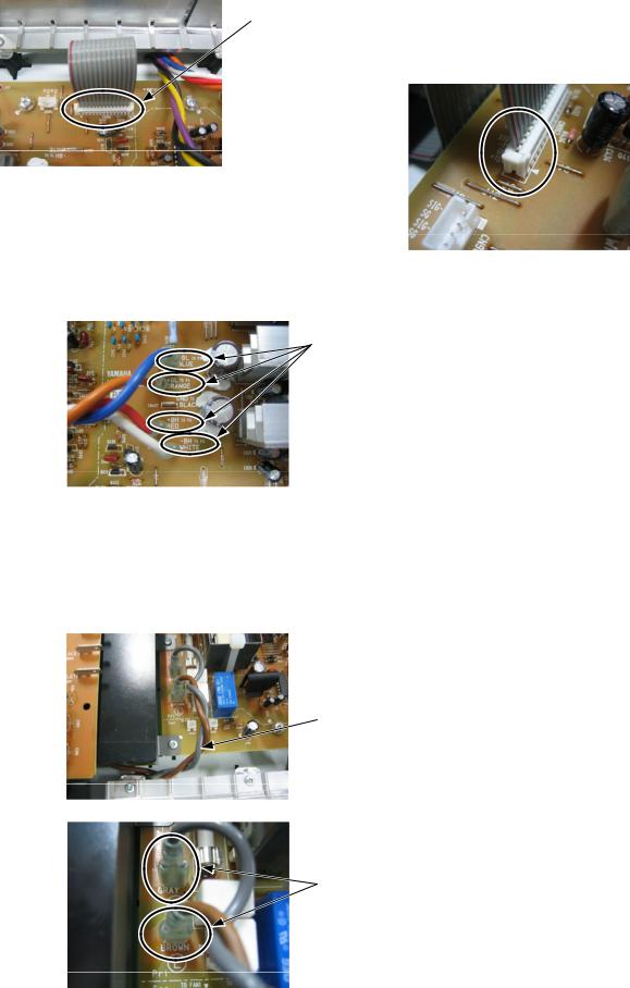
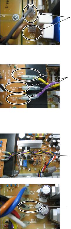
• Between PS circuit board – INLET circuit board PS INLET
H, B, A, O destination
J
A brown, gray wire is bundled and it twists it four times.
4
The color name of the circuit board is matched to the color of the wire harness, and it inserts it in each faston terminal.
ファストン端子に挿入する
Color of wire: Gray → Circuit board display: GRAY
→ GRAY
Color of wire: Brown → Circuit board display: BROWN
→ BROWN
22
EMX5016CF
U destination
There is no necessity that bundles the wire of brown and gray and twists it.
The color name of the circuit board is matched to the color of the wire harness, and it inserts it in each faston terminal.
Color of wire: Gray → Circuit board display : GRAY
Color of wire: Brown → Circuit board display : BROWN
• Between PA unit – OUT circuit board PA OUT
The color name of the circuit board is matched to the color of the wire harness, and it inserts it in each faston terminal.
ファストン端子に挿入する
Color of wire: Yellow → Circuit board display: YELLOW
→ YELLOW
Color of wire: Black → Circuit board display: BLACK
→ BLACK
Color of wire: Violet → Circuit board display: VIOLET
→ VIOLET
• Between PS circuit board – OUT circuit board PS OUT
The wire harness (black) that has gone out of
the OUT circuit board is wrapped around the wire harness that comes from the PA unit three times.
OUT PA3
The color name of the circuit board is matched to the color of the wire harness, and it inserts it in each
faston terminal.
端子に挿入する
Color of wire: Black → Circuit board display: BLACK
→ BLACK
23
EMX5016CF
•Fixation of wire harness
OUT circuit boardOUT
Wire are bundled with tai [205]. (H, B, A, O destination)
205J
U destination is not done.
On PS circuit boardPS
All wire are bundled with tai [250].
250
PS circuit board All wire are bundled with tai [310].
PS |
310 |
PS circuit board |
|
PS |
|||
|
|
• Wire harness fixation of fun
The wire of the fan is passed through two holes that exist in duct PA [280].
PA 280 2
The wire of the fan is fixed with the adhesive tape [315].
 315
315
24
EMX5016CF
The wire is pushed into the crack and it fixes.

The connector in the wire harnesses is inserted in connector CN404 and CN905 of the PS circuit board. (There is no problem even if it inserts it in which connector.)
PS CN404 CN905
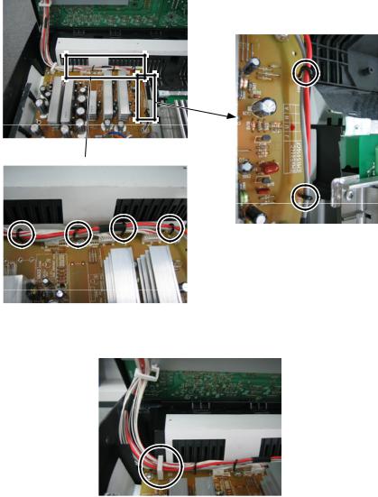
7.Wire Harness Fixation Between Panel Assembly and Bottom Assembly
Ass’y Ass’y
1.The wire harness [430] is inserted in connector CN904 in PS circuit board.
430 PS CN904
The wire harness [440] is inserted in connector CN906 in PS circuit board.
440 PS CN906
The wire harness [450] is inserted in connector CN901 in PS circuit board.
450 PS CN901
The wire harness [460] is inserted in connector CN903 in PS circuit board.
460 PS CN903
The wire harness [465] is inserted in connector CN907 in PS circuit board.
465 PS CN907
460 |
430 |
450 |
440 |
465
25
EMX5016CF
2. The wire harness is fixed with the style pin that has placed to the PS circuit board. (six places)
PS 6
Expansion
Expansion

3. The wire harness that comes from panel assembly is fixed with the wire saddle that has placed to the PS circuit board.
Ass’y PS
26
|
|
|
EMX5016CF |
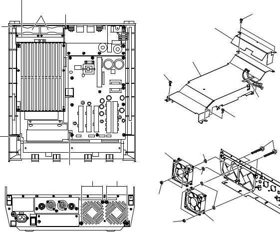
■ DISASSEMBLY PROCEDURES |
|||
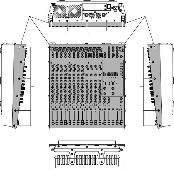
1. Panel Assembly (Time required: 5 min.) |
1. Ass’y 5 |
||
1-1 Remove the three (3) screws marked [720]. (Fig. 1) |
1-1 |
720 3 Fig. 1 |
|
1-2 |
Remove the twelve (12) screws marked [710] (6 on the |
1-2 710 12 6 6 |
|
|
right and 6 on the left). (Fig. 1) |
|
Fig. 1 |
1-3 |
Remove the five (5) screws marked [730]. (Fig. 1) |
1-3 |
730 5 Fig. 1 |
1-4 |
Slide the panel assembly about 10mm toward the front |
1-4 |
Ass’y 10mm |
|
and lift its rear. Then disconnect the connector of the |
|
Ass’y |
|
harness of the panel assembly and remove the harness |
|
|
|
from the clamps. |
1-5 |
Ass’y |
1-5 |
The panel assembly can then be removed. |
|
|
Panel Assembly |
Panel Assembly |
Ass'y |
Ass'y |
[730]
[710] |
[710] |
[720]
[710]: Bind Head Tapping Screw-S 4x8 MFZN2B3 (WE994800) S BIND
[720]: Bind Head Tapping Screw-S 3x8 MFZN2B3 (WF257500) S BIND
[730]: Bind Head Tapping Screw-S 3x8 MFZN2B3 (WF257500) S BIND
(Fig. 1)
27
EMX5016CF
2. DC Fan (Time required: 10 min.) |
2. DC 10 |
||
2-1 Remove the panel assembly. (See procedure 1.) |
2-1 |
Ass’y 1 |
|
2-2 Remove the two (2) plastic rivets marked [290A] and |
2-2 290A 2 |
||
|
remove the fan shield. (Fig. 2) |
|
Fig. 2 |
2-3 Remove the screw marked [300] and plastic rivet marked |
2-3 300 290B |
||
|
[290B]. (Fig. 2) |
|
Fig. 2 |
2-4 Remove the filament tape. (Fig. 2) |
2-4 |
Fig. 2 |
|
2-5 |
Disconnect the connector of the DC fan and pull the |
2-5 DC PA |
|
|
harness out of the hole in the duct PA. |
|
|
2-6 |
Slide the duct PA toward the rear and lift it for removal. |
2-6 PA |
|
|
(Fig. 2) |
|
Fig. 2 |
2-7 |
Remove the two (2) screws marked [80], two (2) nuts |
2-7 |
DC 1 80 2 70 2 |
|
marked [70] and two (2) washers marked [65] per each |
|
65 2 Fig. 2 |
|
DC fan. (Fig. 2) |
2-8 |
DC |
2-8 |
Remove the DC fan. |
|
|
Fan Shield
|
|
|
|
DC Fan |
|
|
|
DC [290A] |
|
[290A] |
|
|
|
|
Fan Shield |
[290A] |
|
|
|
|
|
|
|
|
|
Duct PA |
|
|
|
PA |
|
|
|
[300] |
|
|
|
|
Filament Tape |
|
|
|
|
|
|
|
[290B] |
[300] |
|
|
[80] |
|
|
DC Fan |
|
|
|
DC |
[65] |
|
[290B] |
|
|
|
[80] |
[80] |
[65] |
|
|
|
[65] |
|
|
[70] |
|
|
|
[70] |
DC Fan |
|
|
|
|
|
|
|
DC |
[65]: |
Flat Washer 4x8x0.8 MFZN2W3 (WF578600) |
|
|
[70]: |
Hexagonal Nut M4 #1 (WG169200) 6 |
|
|
[80]: |
Bind Head Screw 4x35 MFZN2B3 (WE999200) BIND |
||
[290A/B]:Plastic Rivet NRP-345 (CB815740) |
|
||
[300]: Bind Head Tapping Screw-P 3x10 MFZN2W3 (WF001000) P |
|||
(Fig. 2)
28
|
|
|
EMX5016CF |
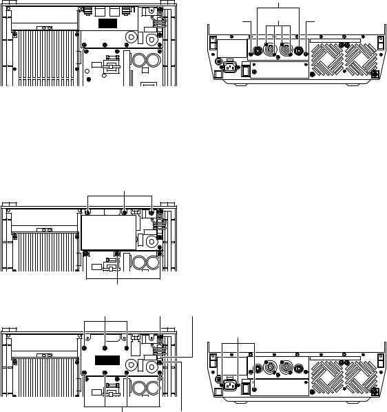
3. |
OUT Circuit Board (Time required: 10 min.) |
3. OUT 10 |
|
3-1 |
Remove the panel assembly. (See procedure 1.) |
3-1 |
Ass’y 1 |
3-2 |
Remove the four (4) screws marked [190], two (2) screws |
3-2 |
190 4 200 2 |
|
marked [200] and two (2) plastic nuts. (Fig. 3) |
|
2 Fig. 3 |
3-3 |
Disconnect the connector of the harness. |
3-3 |
|
3-4 |
The OUT circuit board can then be removed. (Fig. 3) |
3-4 |
OUT Fig. 3 |
|
|
Plastic Nut |
|
|
|
|
[200] |
[190] |
OUT |
[200] |
|
|
|
|
[190]: Flat Fillister H.Tapping 3x8 MFZN2B3 (WF790100) B
[200]: Bind Head Tapping Screw-S 3x8 MFZN2B3 (WF257500) S BIND
(Fig. 3)
[177] (Except for U, A models)
 Shield Inlet A (Except for U, A models)
A
[230]
Coil
[140][170]
[130]
INLET
[140][160]
[130]: Bind Head Tapping Screw-S 3x8 MFZN2B3 (WF257500) S BIND
[140]: PW Head Tapping Screw-P 3x10⁻¹⁰ MFZN2W3 (WF765500) P PWH
[160]: PW Head Tapping Screw-P 3x10⁻¹⁰ MFZN2W3 (WF765500) P PWH
[170]: Bind Head Tapping Screw-S 4x8 MFZN2W3 (WE941800) S BIND
[177]: Bind Head Tapping Screw-S 3x6 MFZN2W3 (WE877900) S BIND
[230]: PW Head Tapping Screw-P 3x10⁻¹⁰ MFZN2W3 (WF765500) P PWH
(Fig. 4)
29
EMX5016CF
4. |
Coil, INLET Circuit Board |
4. INLET 15 |
|
|
(Time required: 15 min.) |
4-1 |
Ass’y 1 |
4-1 Remove the panel assembly. (See procedure 1.) |
4-2 |
OUT 3 |
|
4-2 Remove the OUT circuit board. (See procedure 3.) |
4-3 230 3 177 3 |
||
4-3 Remove the three (3) screws marked [230], three (3) |
|
A |
|
|
|
||
|
screws marked [177] and then remove the shield inlet A |
|
Fig. 4 |
|
|
|
|
|
with the damper inlet. (Fig. 4) |
4-4 160 170 |
|
4-4 Remove the screw marked [160] and the screw marked |
|
Fig. 4 |
|
|
|
||
|
[170] to remove the coil. (Fig. 4) |
4-5 |
130 3 140 7 Fig. 4 |
4-5 Remove the three (3) screws marked [130] and seven |
4-6 |
INLET Fig. 4 |
|
|
(7) screws marked [140]. (Fig. 4) |
|
|
4-6 The INLET circuit board can then be removed. (Fig. 4) |
|
|
|
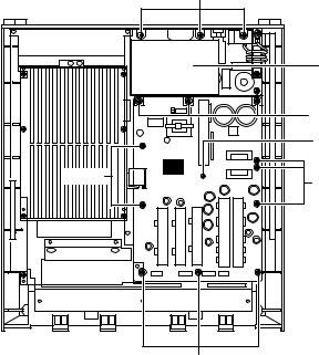
5. PS Circuit Board (Time required: 15 min.) |
5. |
PS 15 |
|
5-1 Remove the panel assembly. (See procedure 1.) |
5-1 |
Ass’y 1 |
|
5-2 Remove the OUT circuit board. (See procedure 3.) |
5-2 |
OUT 3 |
|
5-3 Remove the three (3) screws marked [230A], three (3) |
5-3 230A 3 177 3 |
||
|
screws marked [177] and then remove the shield inlet A |
|
A |
|
with the damper inlet. (Fig. 5) |
|
Fig. 5 |
5-4 Remove the eight (8) screws marked [230B] and the |
5-4 |
230B 8 231 Fig. 5 |
|
|
screw marked [231]. (Fig. 5) |
5-5 |
PS Fig. 5 |
5-5 |
The PS circuit board can then be removed. (Fig. 5) |
|
|
[177] (Except for U, A models)
PS |
[230B] |
[230B] |
Shield Inlet A (Except for U, A models)
A
[230A]
[231]
[230B]
[177]: Bind Head Tapping Screw-S 3x6 MFZN2W3 (WE877900) S BIND
[230A/B]:PW Head Tapping Screw-P 3x10⁻¹⁰ MFZN2W3 (WF765500) P PWH
[231]: Bind Head Tapping Screw-P 3x10 MFZN2W3 (WG776100) P BIND
(Fig. 5)
30
Loading...