


 Loading...
Generator
OWNER’S MANUAL
EF6300iSDE
PLEASE READ AND UNDERSTAND THIS MANUAL |
|
|
LIT-19626-01-52 |
||
COMPLETELY BEFORE OPERATING THE MACHINE. |
7CK-28199-10 |
|
|
|

AE00002
INTRODUCTION
Congratulations on your purchase of your new Yamaha.
This manual will provide you with a good basic understanding of the operation and maintenance of this machine.
If you have any questions regarding the operation or maintenance of your machine, please consult a Yamaha dealer.
AE00022
EF6300iSDE
OWNER’S MANUAL
© 2008 by Yamaha Motor Corporation, U.S.A. 1st Edition, September 2008
All rights reserved.
Any reprinting or unauthorized use without the written permission of Yamaha Motor Corporation, U.S.A. is expressly prohibited.
Printed in Japan
P/N LIT-19626-01-52
IMPOTANT MANUAL INFORMATION
Particularly important information is distinguished in this manual by the following notations.
-
The Safety Alert Symbol means ATTENTION! BECOME ALERT! YOUR SAFETY IS INVOLVED!
w
Failure to follow WARNING instructions could result in severe injury or death to the engine operator, a bystander or a person inspecting or repairing the engine.
cC
A CAUTION indicates special precautions that must be taken to avoid damage to the engine.
NOTE:
A NOTE provides key information to make procedures easier or clearer.
AE00032
w
PLEASE READ AND UNDERSTAND THIS MANUAL COMPLETELY BEFORE OPERATING THE MACHINE.
NOTE:
9Yamaha continually seeks advancements in product design and quality. Therefore, while this manual contains the most current product information available at the time of printing, there may be minor discrepancies between your engine and this manual. If there is any question concerning this manual, please consult a Yamaha dealer.
9This manual should be considered a permanent part of this engine and should remain with this engine when resold.
*Product and specifications are subject to change without notice.

AE00041 |
|
CONTENTS |
|
SAFETY INFORMATION ........................ |
1 |
EXHAUST FUMES ARE |
|
POISONOUS........................................ |
1 |
FUEL IS HIGHLY FLAMMABLE AND |
|
POISONOUS........................................ |
1 |
ENGINE AND MUFFLER MAY BE |
|
HOT ...................................................... |
1 |
ELECTRIC SHOCK PREVENTION...... |
2 |
CONNECTION NOTES ........................ |
3 |
CONNECTION ..................................... |
3 |
EXTENSION CORD NOTES................ |
3 |
LOCATION OF IMPORTANT |
|
LABELS................................................... |
4 |
DESCRIPTION ........................................ |
6 |
Control Panel........................................ |
6 |
CONTROL FUNCTION............................ |
7 |
Engine switch ....................................... |
7 |
Oil warning light (red) ........................... |
7 |
AC protector ......................................... |
8 |
Economy control switch........................ |
8 |
G.F.C.I. receptacle ............................... |
9 |
Voltage select switch ............................ |
9 |
Hour meter.......................................... |
10 |
Power meter ....................................... |
10 |
AC pilot light (green)........................... |
10 |
Overload indicator light (red) .............. |
11 |
Fuel tank cap ...................................... |
11 |
Fuel cock knob ................................... |
12 |
Ground (Earth) terminal...................... |
12 |
Caster lock lever................................. |
12 |
PREPARATION..................................... |
13 |
Fuel..................................................... |
13 |
Engine oil............................................ |
14 |
Battery preparation ............................. |
15 |
PRE-OPERATION CHECK ................... |
17 |
Pre-operation check ........................... |
17 |
OPERATION.......................................... |
18 |
Starting the engine ............................. |
18 |
Stopping the engine............................ |
20 |
Connection ......................................... |
21 |
Application range................................ |
23 |
PERIODIC MAINTENANCE .................. |
25 |
Maintenance chart .............................. |
25 |
Spark plug inspection ......................... |
27 |
Carburetor adjustment........................ |
28 |
Engine oil replacement ....................... |
28 |
Air filter ............................................... |
29 |
Muffler screen and spark arrester....... |
31 |
Fuel tank filter ..................................... |
33 |
Battery ................................................ |
34 |
Recommended battery ....................... |
34 |
Fuse replacement............................... |
35 |
G.F.C.I. receptacle test....................... |
36 |
STORAGE ............................................. |
37 |
Drain the fuel ...................................... |
37 |
Engine ................................................ |
39 |
Battery ................................................ |
40 |
TROUBLESHOOTING .......................... |
42 |
Engine won’t start ............................... |
42 |
Generator won’t produce power ......... |
43 |
SPECIFICATIONS................................. |
45 |
Dimensions......................................... |
45 |
Engine ................................................ |
45 |
Generator ........................................... |
45 |
Battery ................................................ |
45 |
CONSUMER INFORMATION................ |
46 |
Identification number records ............. |
46 |
Machine identification ......................... |
46 |
LIMITED WARRANTY (EFAND |
|
EDL-SERIES) ........................................ |
47 |
EXHAUST EMISSION CONTROL |
|
SYSTEM AND COMPONENTS ......... |
49 |
WIRING DIAGRAM ............................... |
51 |

741-7XFa
741-7XFb
741-7XFc
741-7XFd
741-7XFe
AE00071
SAFETY INFORMATION
AE00072
EXHAUST FUMES ARE POISONOUS
9Never operate the engine in a closed area or it may cause unconsciousness and death within a short time. Operate the engine in a well ventilated area.
AE00075
FUEL IS HIGHLY FLAMMABLE AND POISONOUS
9Always turn off the engine when refuelling.
9Never refuel while smoking or in the vicinity of an open flame.
9Take care not to spill any fuel on the engine or muffler when refueling.
9If you swallow any fuel, inhale fuel vapor, or allow any to get in your eye(s), see your doctor immediately. If any fuel spills on your skin or clothing, immediately wash with soap and water and change your clothes.
9When operating or transporting the machine, be sure it is kept upright. If it tilts, fuel may leak from the carburetor or fuel tank.
AE00843
ENGINE AND MUFFLER MAY BE HOT
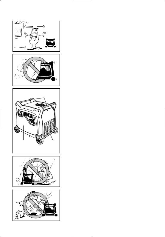
9Place the machine in a place where pedestrians or children are not likely to touch the machine.
9 Avoid placing any flammable materials near the exhaust outlet during operation.
741-7XFf
– 1 –
|
9 |
Keep the machine at least 1 m (3 ft) from buildings |
a |
or other equipment, or the engine may overheat. |
|
a 1 m (3 ft)
741-7XFg
|
741-7XFh |
|
1 |
1 |
1 |
|
794-7CK |
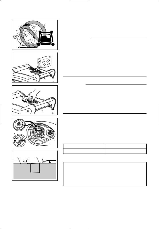
741-7XFi
9 Avoid operating the engine with a dust cover.
9Be sure to carry the generator only by its carrying handles 1.
AE00083
ELECTRIC SHOCK PREVENTION
9 Never operate the engine in rain or snow.
9Never touch the machine with wet hands or electrical shock will occur.
741-7XFj
– 2 –

1
763-7CKa
1
2
1
2
741-7XFk
9Connect the ground lead of the machine to the ground (earth) terminal 1 and connect the end to the ground electrode buried in the ground.
AE00088
CONNECTION NOTES
9Avoid connecting the generator to commercial power outlet.
9Avoid connecting the generator in parallel with any other generator.
1 Correct
2 Incorrect
AE00091
CONNECTION
w
Before the generator can be connected to a building’s electrical system, a licensed electrician must install an isolation (transfer) switch in the building’s main fuse box. The switch is the connection point for generator power and allows selection of generator or main line power to the building. This will prevent the generator from charging the main power line (backfeeding) when the main power supply has failed or has been turned off for line repair. Backfeeding can electrocute or injure line maintenance personnel. Also, generator and building electrical system damage can occur when normal operating power returns if unit is used without an isolation switch.
AE00086
EXTENSION CORD NOTES
Extension cords should be protected by a tough flexible rubber sheath (IEC 245) or the equivalent to withstand mechanical stresses.
– 3 –

AE00062
LOCATION OF IMPORTANT LABELS
Please read the following labels carefully before operating this machine.
NOTE:
Maintain or replace safety and instruction labels, as necessary.
3 1 2 7 5
4
6
1 |
2 |
 DANGER
Using a generator indoors CAN KILL YOU IN MINUTES.
Generator exhaust contains carbon monoxide. This is a poison you cannot see or smell.
NEVER use inside a home |
Only use |
OUTSIDE and |
or garage, EVEN IF doors |
far away |
from windows, |
and windows are open. |
door, and vents. |
|
|
|
|
WARNING
Electrocution or property damage can occur: Do not connect this generator to any building’s electrical system unless an isolation switch has been installed by a licensed electrician. Refer to the owner’s manual.
7XF-2415A-00
– 4 –

3
qWARNING
8READ THE OWNER‘S MANUAL AND ALL LABELS BEFORE OPERATING.
8ONLY OPERATE IN WELL-VENTILATED AREAS.
EXHAUST GAS CONTAINS POISONOUS CARBON MONOXIDE.
8CHECK FOR SPILLED FUEL OR FUEL LEAKS.
8STOP ENGINE BEFORE REFUELING.
8DO NOT OPERATE NEAR FLAMMABLE MATERIALS.
8ELECTROCUTION CAN OCCUR IF GENERATOR IS USED IN RAIN, SNOW, OR NEAR WATER. KEEP THIS UNIT DRY AT ALL TIMES.
4
qAVERTISSEMENT
8 LISEZ LE MODE D‘EMPLOI ET TOUTES LES ETIQUETTES AVANT DE
FAIRE FONCTIONNER LA MACHINE.
8 FAITES FONCTIONNER UNIQUEMENT DANS DES LIEUX BIEN AERES.
LES GAZ D‘ECHAPPEMENT CONTIENNENT 0U MONOXYDE DE CARBONE. 8 VERIFIEZ SI DU CARBURANT A ETE RENVERSE DU S‘IL FUIT.
8 ARRETEZ LE MOTEUR AVANT DE FAIRE LE PLEIN DE CARBURANT. 8 N‘UTILISEZ PAS A PROXIMITE DE MATERIAUX INFLAMMABLES.
8 IL Y A RISQUE D‘ELECTROCUTION SI LE GENERATEUR FONCTIONNE
SOUS LA PLUIE, DANS LA NEIGE, OU PRES DE L‘EAU. GARDEZ LA MACHINE AUSEC EN TOUTES CIRCONSTANCES.
6
HOT EXHAUST
7WL-28176-10
5
q CAUTION
Use the specified spark plug only.
OIL
|
zzzzzz |
AC output |
zzHz |
Rated |
zzzzVA |
|
zzzV |
Phase |
Single |
Fuel |
Gasoline |
Specified plug:BPR4ES(NGK)
7
Important Emissions Information
YAMAHA MOTOR POWERED PRODUCTS CO.,LTD.
This engine meets **** California exhaust and evaporative emission regulations for small off-road engines.
This engine conforms to Phase 2 U.S.EPA regulations for small nonroad engines.
EMISSIONS COMPLIANCE PERIOD : CATEGORY A(EPA)
EF: *YMXS.3572EA |
DISPLACEMENT: 357cc |
EVAP F: CMYMX23A |
EMISSION CONTROL SYSTEM: EM |
This engine is certified to operate on unleaded gasoline. |
|
ENGINE OIL: SAE10W-30 |
TYPE: SE |
No other adjustments needed.
YAMAHA MOTOR POWERED PRODUCTS CO.,LTD.
MADE IN JAPAN
7CK-24164-10
The air index of this engine is 3 (California only)
0 |
2 |
4 |
6 |
8 |
10 |
MOST CLEAN |
|
|
|
|
LEAST CLEAN |
Note: The lower the air index, the less the pollution. This engine is certified to be emissions compliant for the following use:
MODERATE |
INTERMEDIATE |
X |
EXTENDED |
(250 HOURS) |
(500 HOURS) |
(1000 HOURS) |
Check owner's manual for further details.
– 5 –
1 |
2 3 |
1 |
1
793-7CKa
4
1
8 7 6 |
5 793-7CKb |
1 2 |
3 |
4 |
5 |
|
|
6 |
|
|
7 |
e w q |
0 9 8 |
793-7CK |
DESCRIPTION
AE00102
1 Carrying handles (shaded)
2 Fuel tank cap
3 Fuel gauge
4 Muffler
5 Caster lock lever
6 Oil filler cap
7 Oil drain bolt
8 Battery
AE00103
Control panel
1 Hour meter
2 Power meter
3 G.F.C.I. receptacle
4 AC protector
5 AC receptacle
6 Engine switch
7 Fuel cock knob
8 Voltage select switch
9 Ground (Earth) terminal
0 Economy control switch q Overload indicator light w AC pilot light
e Oil warning light
– 6 –
q
we
763-119
AE00101
CONTROL FUNCTION
AE00121
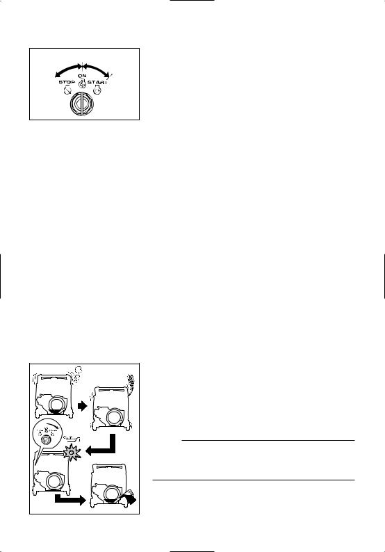
Engine switch
The engine switch controls the ignition system.
17 “ON”
Ignition circuit is switched on.
The engine can be started.
25 “STOP”
Ignition circuit is switched off.
The engine will not run.
36 “START”
Starting circuit is switched on.
The starter motor starts and the engine can be started. Take your hand off the switch immediately after the engine starts.
700-7XF |
AE00111
Oil warning light (red)
When the oil level falls below the lower level, the oil warning light comes on and then the engine stops automatically. Unless you refill with oil, the engine will not start again.
NOTE:
If the engine stalls or does not start, turn the engine switch to “START”. If the oil warning light comes on, the engine oil is insufficient. Add oil and restart.
– 7 –
1 |
3 |
|
2 |
4 |
793-7CKe |
|
2 |
1 |
763-238a |
ECON.SW
 ON OFF
763-124a
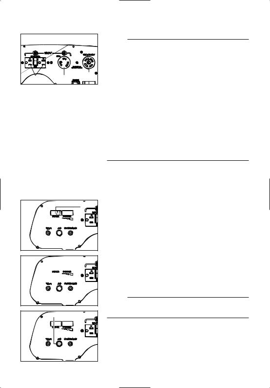
AE00134
AC protector
The AC protector 1 trips when total amount of the receptacles 2 loads exceed 20A.
The AC protector 3 trips when the receptacle 4 loads exceed 30A.
Press the switches to reset the AC protectors.
1  I “Set”
2  3 “Reset”
AE00142
Economy control switch
1I “ON”
When the economy control switch is turned to “ON”, the economy control unit controls the engine speed according to the connected load. The results are better fuel consumption and less noise.
23 “OFF”
When the economy control switch is turned to “OFF”, the engine runs at the rated r/min (3,400 r/min) regardless of whether is a load connected or not.
NOTE:
The economy control switch must be turned to “OFF” when using electric devices that require a large starting current, such as a compressor of a submergible pump.
– 8 –

q |
|
|
|
|
|
|
|
|
AE00848 |
|||||||
|
|
|
|
|
|
|
|
G.F.C.I. receptacle |
||||||||
|
|
|
|
|
|
|
|
|
|
|
|
|
|
|
||
|
|
|
|
|
|
TEST |
TEST |
|
|
|
|
|
|
|
w |
|
|
|
|
|
|
|
|
|
|||||||||
|
|
|
|
|
|
RESET |
RESET |
|
|
|
|
|
|
|
TO REDUCE THE CHANCE OF ELECTRICAL |
|
|
|
|
|
|
|
|
|
|
|
|
|
|
|
|
SHOCK: |
|
|
|
|
|
|
|
|
|
w |
|
|
|
9 Do not attempt to operate electric devices if |
||||
|
|
|
|
|
|
|
|
|
763-083c |
the ground fault circuit interrupter reset button |
||||||
|
|
|
|
|
|
|
|
|
|
|
|
|
||||
|
|
|
|
|
|
|
|
|
|
|
|
|
|
|
pops out repeatedly during use. |
|
|
|
|
|
|
|
|
|
|
|
|
|
|
|
|
||
|
|
|
|
|
|
|
|
|
|
|
|
|
|
|
||
e9 Test the ground fault circuit interrupter during
the pre-operation checks according to the maintenance instructions on page 36.
9Remember that only receptacle labeled “GFCI” have ground fault circuit interrupter protection.
763-060
The G.F.C.I. (Ground Fault Circuit Interrupter) 1 shuts off power to the protected receptacles if a ground fault (electrical leak) is detected.
If the reset button 2 pops out 3, the electric devices connected into the receptacle may be faulty. If this happens, check the electric devices carefully. If the electric devices appears to be in good condition, press the reset button firmly until a click is heard. This will restore power. If the reset button pops out again, disconnect all the electric devices immediately. Have the electric devices inspected and repaired by a qualified repairperson before attempting to use them again.
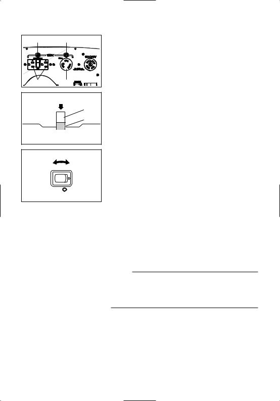
Voltage select switch
cC
Do not operate the voltage select switch while the engine is running.
NO SWITCHING DURING OPERATION.
120/240V 120V
WHEN SWITCHING TO 120V. THE 120/240V OUTLET CANNOT BE USED.
1 “120/240V”
When the voltage select switch is turned to “120/240V” 1, the generator supplies both 120V and 240V.
2 “120V”
When the voltage select switch is turned to “120V” 2, 799-7CK the generator supplies 120V only.
– 9 –
1 |
2 |
3 |
793-7CKf |
NOTE:
If you operate the generator with the voltage select switch in the 120/240V-position, the electric current will be limited for the 120V-receptacles.
When you use either receptacle 1 or 2 AND receptacle 3 at the same time, the total electric current provided will be equal to or even less than 22.9A.
For example:
If the 240V-receptacle provides 10A, the 120V-recep- tacles 1 and 2 can be used up to 12.9A each.
In case the load exceeds 22.9A, the overload indicator light will turn on and the generator will stop. (At this moment the segments of the powermeter may not reach 10)
If you operate the generator with the voltage select switch in the 120V-position, the receptacles 1 and 2 can supply rated current (45.8A).
1 |
Hour meter |
|
The hour meter 1 shows the total number of hours |
||
|
||
|
the generator has been run. |
|
763-7CKf |
|

 1
1
763-7CKg
1
763-7CKc
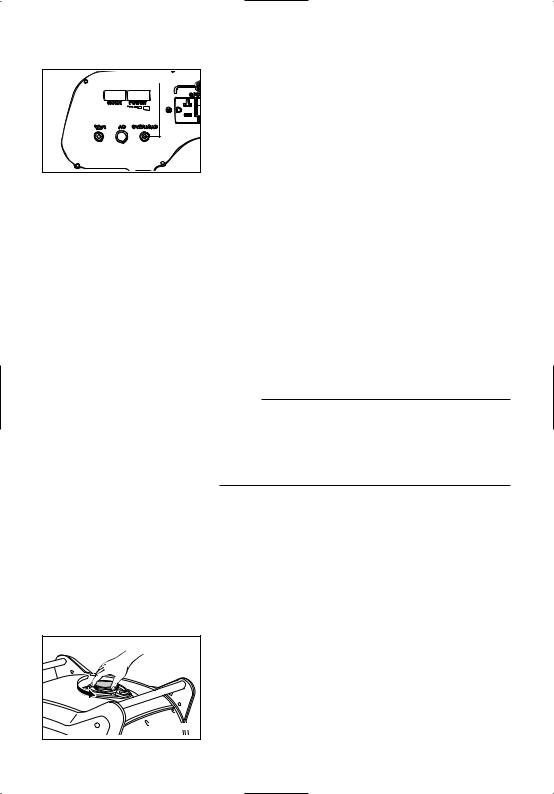
Power meter
The power meter 1 shows the amount of electric current used by a barmeter.
The generator output is normal when the segments of the barmeter appear.
NOTE:
When 10 segments appear, the generator has almost reached its rated output.
AC pilot light (green)
The AC pilot light 1 comes on when the engine starts and produces power.
– 10 –
1
763-7CKd
AE01087
Overload indicator light (red)
The overload indicator light 1 comes on when an overload of a connected electrical device is detected, the inverter control unit overheats, or the AC output voltage rises. Then, the AC protector will trip, stopping power generation in order to protect the generator and any connected electric devices. The AC pilot light (green) will go off and the overload indicator light (red) will stay on, but the engine will not stop running.
When the overload indicator light comes on and power generation stops, proceed as follows:
1.Turn off any connected electric devices and stop the engine.
2.Reduce the total wattage of connected electric devices within the rated output.
3.Check for blockages in the cooling air inlet and around the control unit. If any blockages are found, remove.
4.After checking, restart the engine.
NOTE:
The overload indicator light may come on for a few seconds at first when using electric devices that require a large starting current, such as a compressor or a submergible pump. However, this is not a malfunction.
707-7XFb |
Fuel tank cap
Remove the fuel tank cap by turning it counterclockwise.
– 11 –
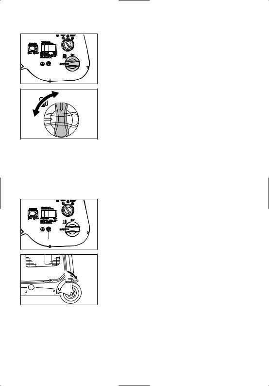
Fuel cock knob
The fuel cock supplies fuel from the fuel tank to the carburetor.
The fuel cock has two positions.
763-7CKb
1
ON
2
OFF
705-073d
1
763-7CKa
1 “ON”
With the knob in this position, fuel flows to the carburetor. Normal using is done with the knob in this position.
2 “OFF”
With the knob in this position, fuel will not flow. Always turn the knob to this position when the engine is not running.
Ground (Earth) terminal
Ground (Earth) terminal 1 connects the earth line for prevention of electric shock.
When the electric device is earthed, always the generator must be earthed.
Caster lock lever
The caster lock lever stops moving the generator.
1 
2 1 “Release”
2 “Lock”
788-7CKh
– 12 –
741-7XFl |
707-7XFc |
|
707-7XFa |
2 |
|
|
1 |
|
707-7XF |
3 |
4 |
PREPARATION
AE00856
Fuel
w
9Fuel is highly flammable and poisonous. Check “SAFETY INFORMATION” (See page 1) carefully before filling.
9Do not overfill the fuel tank, otherwise it may overflow when the fuel warms up and expands.
9After fill the fuel, make sure the fuel tank cap is tightened securely.
cC
9Immediately wipe off spilled fuel with a clean, dry, soft cloth, since fuel may deteriorate painted surfaces or plastic parts.
9Use only unleaded gasoline. The use of leaded gasoline will cause severe damage to internal engine parts.
Make sure there is sufficient fuel in the tank.
When refueling, be sure to fill the tank to the bottom edge of the fuel filter 4.
1 Fuel level gauge
2 Red line
“F” |
Full |
Red line 2 |
Empty |
3 Fuel level
Recommended fuel: Unleaded gasoline
Fuel tank capacity: Total:
17.0 L (3.17 US gal, 2.64 Imp gal)
Your Yamaha engine has been designed to use regular unleaded gasoline with a pump octane number ((R + M)/2) of 86 or higher, or research octane number of 91 or higher.
– 13 –
Loading...