


EF4600A
Table of contents
 Loading...
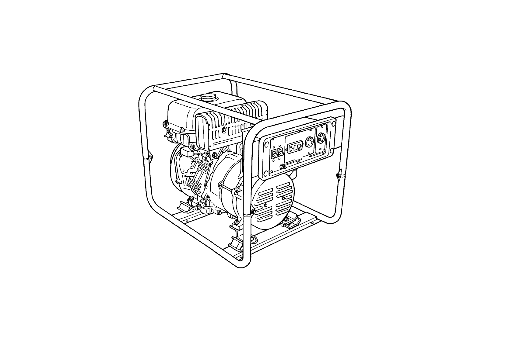
YAMAHA GENERATOR
EF4600A
(7WX2) (120V/240V–60Hz) USA
EF6600A
(7WY2) (120V/240V–60Hz) USA
117WX–110E1

EF4600A/EF6600A
PARTS CATALOGUE
E2001 by Yamaha Motor Co., Ltd.
1st Edition, Sep. 2001
All rights reserved.
Any reprinting or unauthorized use
without the written permission of
Yamaha Motor Co., Ltd.
is expressly prohibited.
Printed in Japan
FOREWORD
This Parts Catalogue is related to the parts for the model(s) in the below frame. When you are
ordering replacement parts, please refer to this Parts Catalogue and quote both part numbers
and part names correctly.
1. Modifications or additions which have been made after issue of the Parts Catalogue
will be announced in the Yamaha Parts News.
It is advisable that you make necessary corrections to the Parts Catalogue according
to the Yamaha Parts News.
2. Abbreviations
The following abbreviations are used in this Parts Catalogue.
“UR” Use specified parts number.
“UN” Use as many as needed.
“AP” Alternate Parts
“LM” Local Made (Parts need to be ordered locally)
“F#” Frame No. (Applicable machine No.)
3. Parts, which are to be supplied in an assembly, are listed with a dot(.) in front of the
part name as shown below.
EXAMPLE
CARBURETOR ASSY
.JET, PILOT
.NOZZLE, MAIN
4. Number of component for assembly
The numeral appearing to the right of each component part indicates the quantity of
parts for each assembly unit.
EXAMPLE
PART NO. DESCRIPTION Q’TY REMARKS
2F5–83310–60 FRONT FLASHER LIGHT ASSY 2
115–83311–60 .BULB (6V–18W) 1
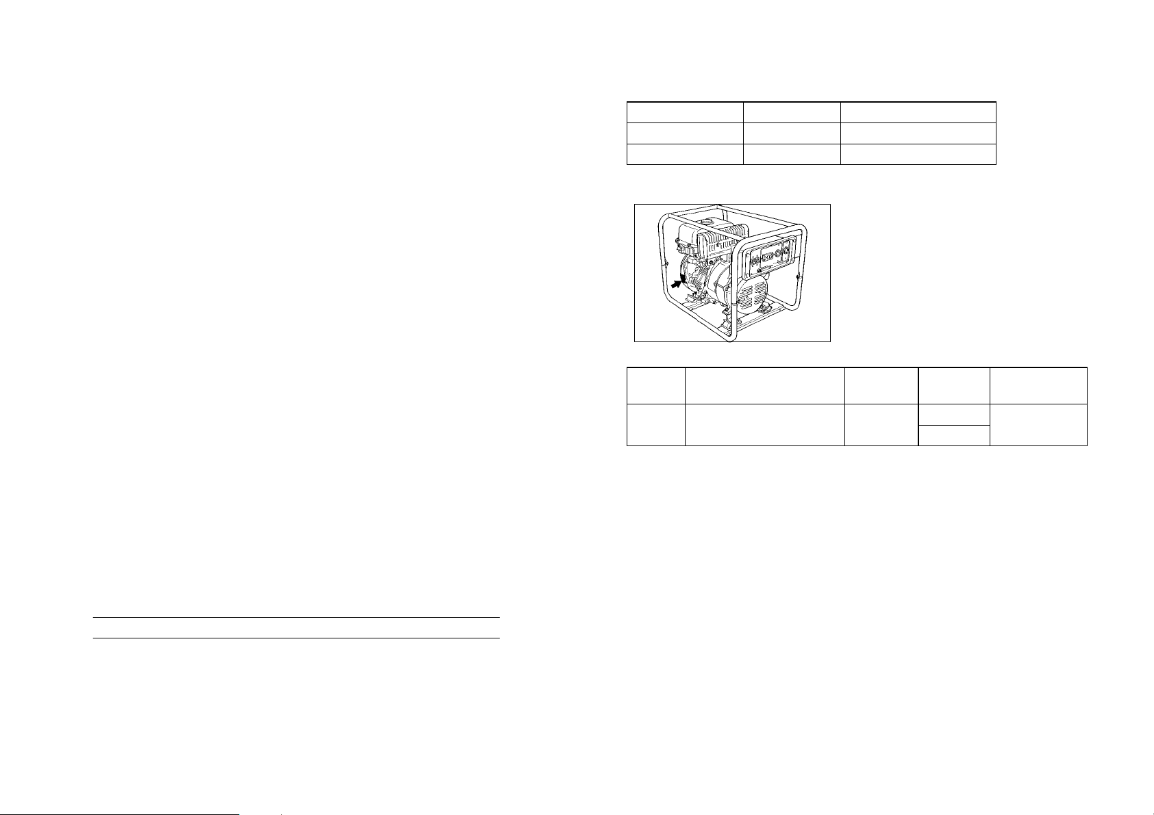
5. Applicable Starting Serial No. and Color Code
MODEL NAME
MODEL TYPE FRAME NO.
EF4600A 7WX2 7WX–200101
EF6600A 7WY2 7WY–200101
Engine Serial No.
Color
Code
Color Name
Abbrevi-
ation
MODEL
Country
(destination)
7WX2
00NJ FARAWAY BLUE FWB
7WY2
USA
6. Note that the illustrations for reference in finding parts numbers, not to be used for
assembling. When assembling, please use the applicable service manual.
7. The asterisk (*) before a reference number indicates modification items after the first
edition.

CONTENTS
CYLINDER 1.........................................
CRANKSHAFT. PISTON 2.............................
GOVERNOR 1 3......................................
CAMSHAFT.VALVE 4..................................
AIR SHROUD. STARTER 5.............................
INTAKE 6............................................
CARBURETOR 7.....................................
EXHAUST 8..........................................
CRANKCASE 9.......................................
FRAME 10............................................
FUEL TANK 11........................................
MAGNETO 12.........................................
ELECTRICAL 13.......................................
GENERATOR 1 (EF4600A) 14...........................
GENERATOR 2 (EF6600A) 16...........................
CONTROL BOX 1 (EF4600A) 18.........................
CONTROL BOX 2 (EF6600A) 20.........................
LABELS 22............................................
INDEX
NUMERICAL INDEX 23.................................
1
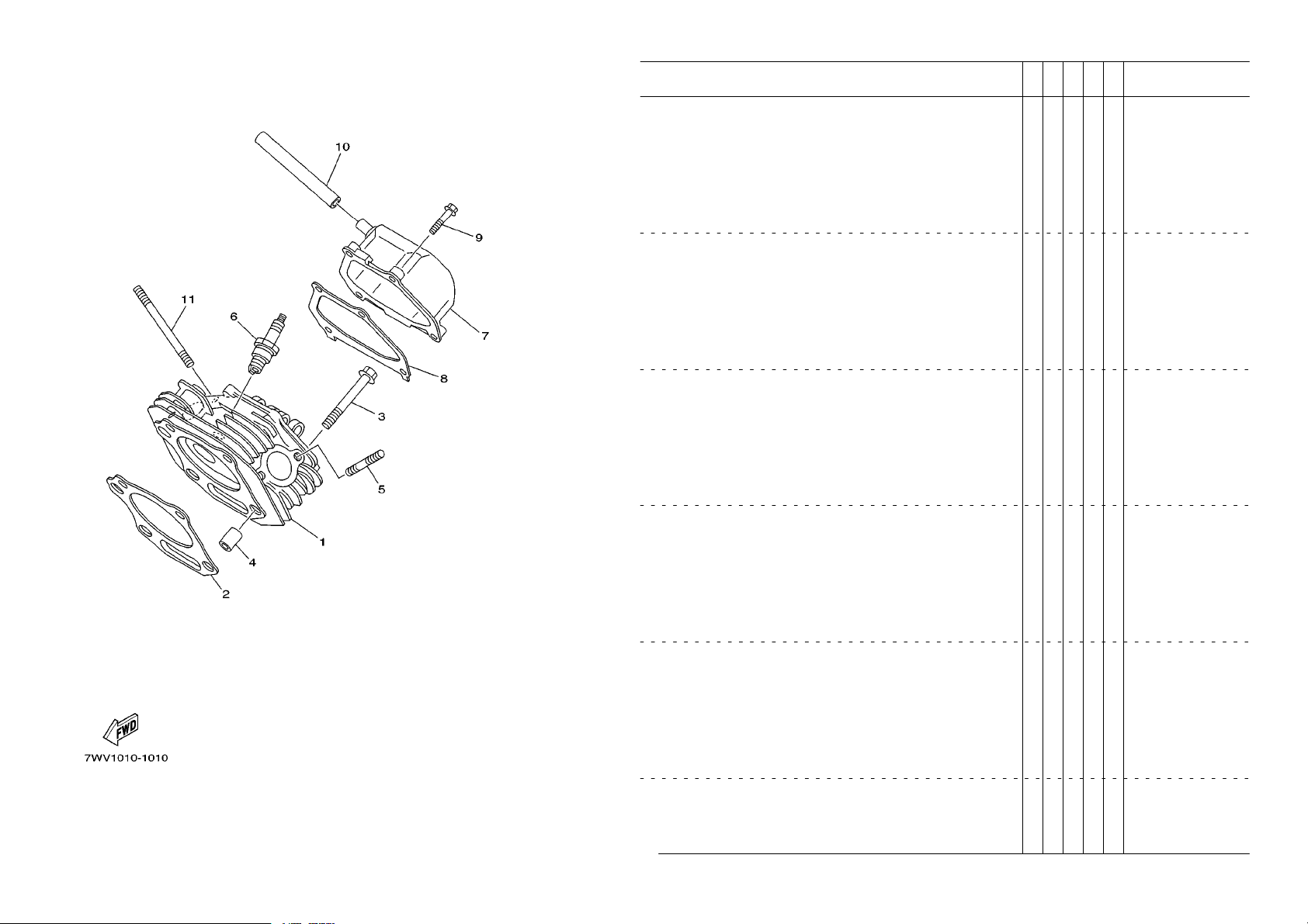
FIG. 1 CYLINDER
1 7WE–11111–00 HEAD, CYLINDER 1 1
7WG–11111–00 HEAD, CYLINDER 1 1
2 7WE–11181–00 GASKET, CYLINDER HEAD 1 1
7WG–11181–00 GASKET, CYLINDER HEAD 1 1
3 95817–10070 BOLT, FLANGE 4 4
4 99530–14016 PIN, DOWEL 2 2
5 95627–08618 BOLT, STUD 2 2
6 94702–00331 PLUG, SPARK (BPR4ES) 1 1
7 7WG–11190–00 COVER, CYLINDER HEAD 1 1 1
8 JN6–11193–00 GASKET, HEAD COVER 1 1 1
9 95827–06030 BOLT, FLANGE 4 4
10 7RH–11166–00 PIPE, BREATHER 1 1 1
11 95607–08700 BOLT, STUD 2 2
PART NO. DESCRIPTION REMARKS
REF.
NO.
7WX2
7WY2
2
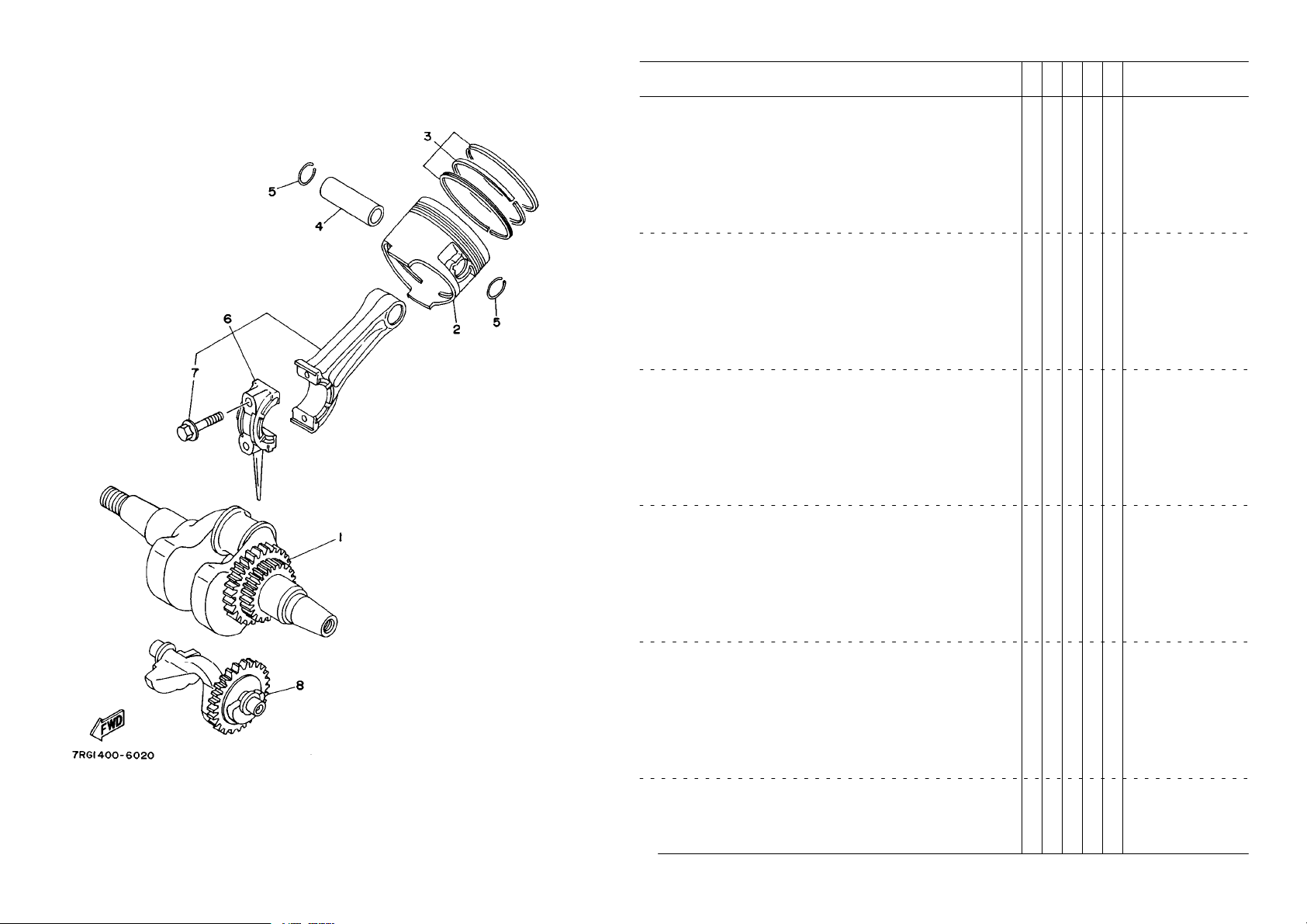
FIG. 2 CRANKSHAFT. PISTON
1 7WR–11400–00 CRANKSHAFT ASSY 1
7WR–11400–10 CRANKSHAFT ASSY 1
2 JN6–11631–00–A0 PISTON (STD) 1
7RH–11631–00–A0 PISTON (STD) 1
JN6–11635–00 PISTON (0.25MM O/S) 1 AP
7RH–11635–00 PISTON (0.25MM O/S) 1 AP
JN6–11636–00 PISTON (0.50MM O/S) 1 AP
7RH–11636–00 PISTON (0.50MM O/S) 1 AP
3 JN6–11610–00 PISTON RING SET (STD) 1
7RH–11603–00 PISTON RING SET (STD) 1
JN6–11610–10 PISTON RING SET (0.25MM O/S) 1 AP
7RH–11604–00 PISTON RING SET (0.25MM O/S) 1 AP
JN6–11610–20 PISTON RING SET (0.50MM O/S) 1 AP
7RH–11605–00 PISTON RING SET (0.50MM O/S) 1 AP
4 447–11633–00 PIN, PISTON 1
583–11633–00 PIN, PISTON 1
5 93450–21053 CIRCLIP 2 2
6 JN6–11650–00 CONNECTING ROD ASSY 1 1
7 JN6–11654–00 .BOLT, CONNECTING ROD 2 2
8 7WG–11454–00 WEIGHT 1 1 1
PART NO. DESCRIPTION REMARKS
REF.
NO.
7WX2
7WY2
3
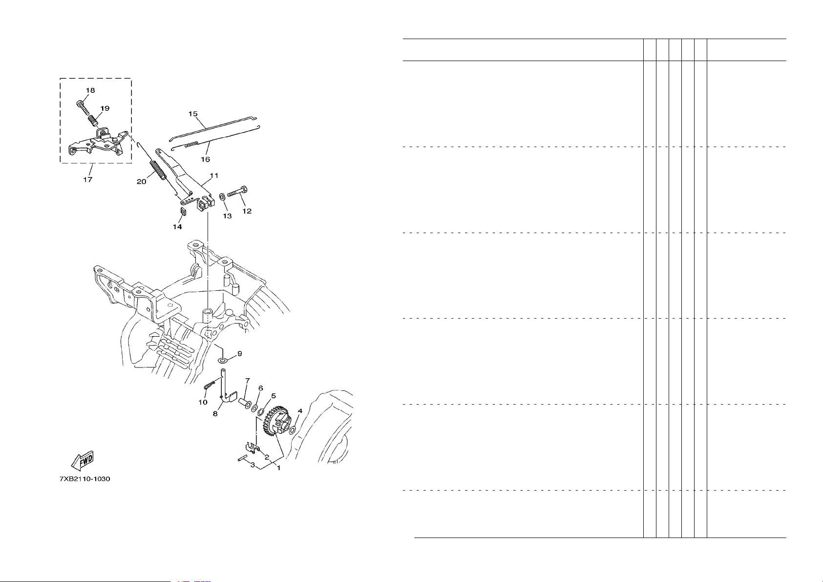
FIG. 3 GOVERNOR 1
1 7RH–11970–00 FLYWEIGHT SHAFT ASSY. 1 1
2 7RH–11913–00 .WEIGHT 3 3
3 7FK–11914–00 .SHAFT, WEIGHT 3 3
4 90201–065K7 WASHER, PLATE 1 1
5 93440–06107 CIRCLIP 1 1
6 90201–067L0 WASHER, PLATE 1 1
7 7KY–11917–00 COLLAR 1 1
8 7RH–11922–00 FORK, GOVERNOR 1 1
9 90201–08092 WASHER, PLATE 2 2
10 90468–12006 CLIP 1 1
11 7RK–11924–10 ARM, GOVERNOR 1 1
12 97027–06030 BOLT 1 1
13 92907–06600 WASHER, PLATE 1 1
14 90173–06017 NUT, SQUARE 1 1
15 7RH–11928–00 ROD, LINK 1 1
16 90506–04458 SPRING, TENSION 1 1
17 7RK–11950–11 ADJUST PLATE COMP . 1 1
18 98507–05030 .SCREW, PAN HEAD 1 1
19 90501–090A8 .SPRING, COMPRESSION 1 1
20 7RK–11925–20 SPRING, GOVERNOR 1 1
PART NO. DESCRIPTION REMARKS
REF.
NO.
7WX2
7WY2
4
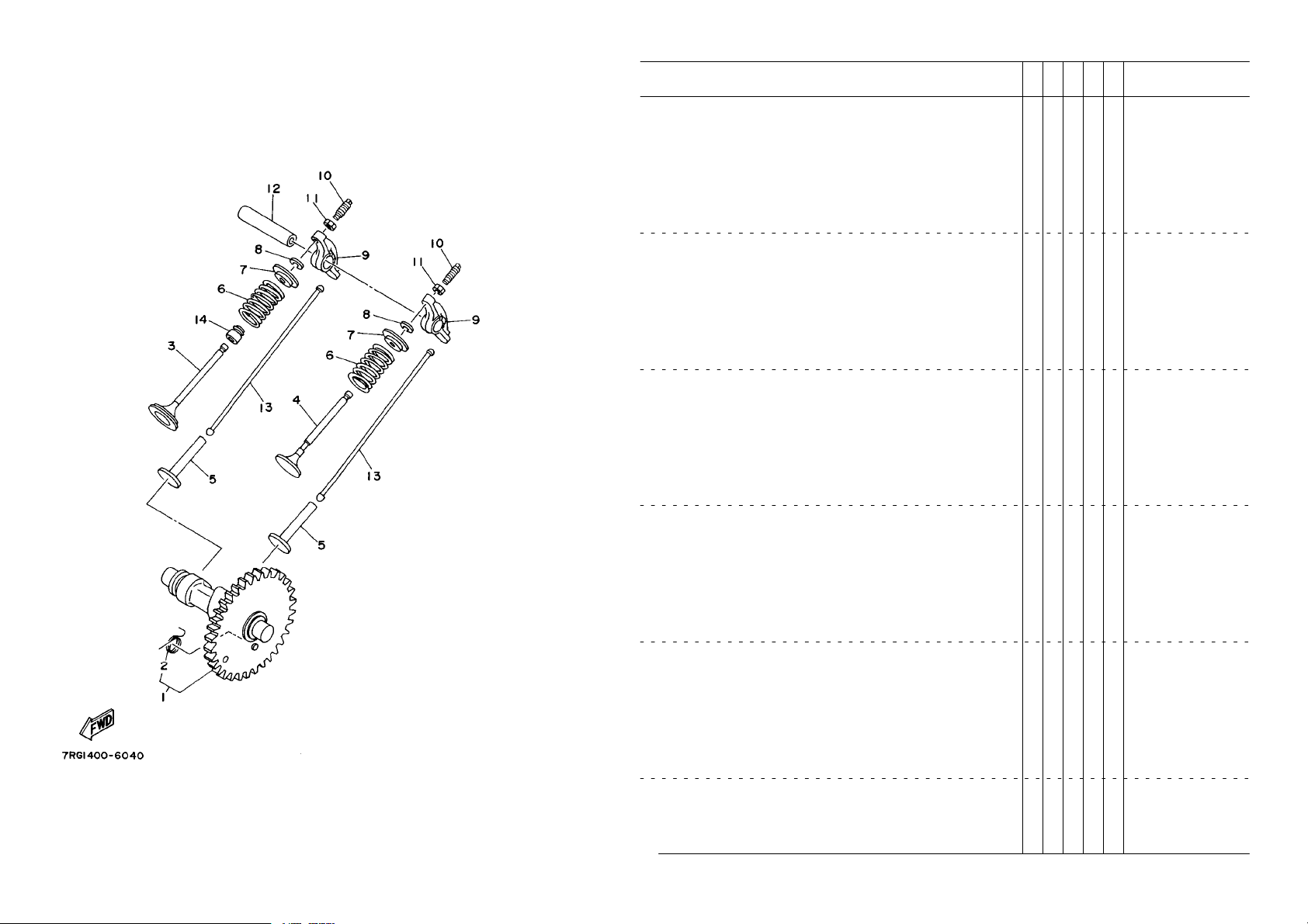
FIG. 4 CAMSHAFT.VALVE
1 7WG–12170–00 CAMSHAFT ASSY 1 1 1
2 7WG–12287–00 .SPRING, DECOMPRESSION 1 1
3 JN6–12111–01 VALVE, INTAKE 1 1
4 7RH–12121–00 VALVE, EXHAUST 1 1
5 JN6–12153–00 LIFTER, VALVE 2 2
6 90501–264A9 SPRING, COMPRESSION 2 2
7 J38–12117–01 RETAINER, VALVE SPRING 2 2
8 J38–12118–00 COTTER, VALVE 2 2
9 JN6–12151–00 ARM, VALVE ROCKER 2 2
10 22F–12159–00 SCREW, VALVE ADJUSTING 2 2
11 90170–05302 NUT 2 2
12 J38–12156–00 SHAFT, ROCKER 2 1 1
13 JN6–12154–00 ROD, VALVE PUSH 2 2
14 4G0–12119–00 SEAL, VALVE STEM 1 1
PART NO. DESCRIPTION REMARKS
REF.
NO.
7WX2
7WY2
Loading...