


VHF/UHF
ULTRA-COMPACT DUAL-BAND TRANSCEIVER
WITH WIDE BAND COVERAGE
OPERATING MANUAL
VERTEX STANDARD CO., LTD.
4-8-8 Nakameguro, Meguro-Ku, Tokyo 153-8644, Japan
VERTEX STANDARD
US Headquarters
10900 Walker Street, Cypress, CA 90630, U.S.A.
International Division
8350 N.W. 52nd Terrace, Suite 201, Miami, FL 33166, U.S.A.
YAESU EUROPE B.V.
P.O. Box 75525, 1118 ZN Schiphol, The Netherlands
YAESU UK LTD.
Unit 12, Sun Valley Business Park, Winnall Close
Winchester, Hampshire, SO23 0LB, U.K.
VERTEX STANDARD HK LTD.
Unit 5, 20/F., Seaview Centre, 139-141 Hoi Bun Road, Kwun Tong, Kowloon, Hong Kong

Contents
General Description .......................................... |
1 |
Controls & Connections ................................... |
2 |
Keypad Functions ............................................ |
3 |
Display Icons & Indicators ............................. |
3 |
Accessories & Options ...................................... |
4 |
Installation of Accessories ................................ |
5 |
Antenna Installation ........................................ |
5 |
Installation of the Supplied Belt Clip ............. |
5 |
Installation of FNB-82LI Battery Pack .......... |
6 |
Interface of Packet TNCs ................................. |
7 |
Operation ............................................................ |
8 |
Switching Power On and Off .......................... |
8 |
Adjusting the Volume Level ........................... |
8 |
Squelch Adjustment ........................................ |
9 |
Selecting the Operating Band ....................... |
10 |
Frequency Navigation ................................... |
11 |
Transmission ................................................. |
12 |
Keyboard Locking ......................................... |
13 |
Keypad/LCD Illumination ............................ |
14 |
Disabling the Keypad Beeper ....................... |
14 |
Advanced Operation ....................................... |
15 |
Checking the Battery Voltage ....................... |
15 |
Changing the Channel Steps ......................... |
15 |
Changing the Receiving Mode ..................... |
16 |
Display Dimmer ............................................ |
16 |
RF Squelch .................................................... |
17 |
Repeater Operation ....................................... |
18 |
CTCSS Operation .......................................... |
21 |
DCS Operation .............................................. |
22 |
Tone Search Scanning ................................... |
23 |
CTCSS/DCS Bell Operation ......................... |
24 |
Split Tone Operation ..................................... |
24 |
Tone Calling (1750 Hz) ................................ |
25 |
ARTS (Automatic Range Transponder System) ....... |
26 |
DTMF Operation ........................................... |
29 |
Emergency Channel Operation ..................... |
31 |
ATT (Front End Attenuator) ......................... |
31 |
Receive Battery Saver Setup ......................... |
32 |
TX Battery Saver ........................................... |
32 |
Automatic Power-Off (APO) Feature ........... |
33 |
Transmitter Time-Out Timer (TOT) ............. |
34 |
Busy Channel Lock-Out (BCLO) ................. |
34 |
Changing the TX Deviation Level ................ |
35 |
Memory Mode .................................................. |
36 |
Regular Memory Operation .......................... |
37 |
Memory Storage ........................................ |
37 |
Storing Independent |
|
Transmit Frequencies (“Odd Split”) ........ |
37 |
Memory Recall .......................................... |
38 |
HOME Channel Memory ......................... |
38 |
Labeling Memories ................................... |
39 |
Memory Offset Tuning ............................. |
40 |
Masking Memories ................................... |
41 |
Moving Memory Data to the VFO ........... |
41 |
Mem0ory Bank Operation ........................ |
42 |
Memory Only Mode .................................. |
43 |
Special Memory Channel Operation ............ |
44 |
Weather Broadcast Channels .................... |
44 |
VHF Marine Channels .............................. |
45 |
Sort-wave Broadcast Station |
|
Memory Channels ..................................... |
46 |
Scanning ............................................................ |
47 |
VFO Scanning ............................................... |
48 |
How to skip (Omit) a Frequency |
|
during VFO Scan ...................................... |
49 |
Memory Scanning ......................................... |
50 |
Temporary Memory Skip .......................... |
50 |
How to Skip (Omit) a Channel |
|
during Memory Scan Operation ............... |
50 |
Preferential Memory Scan ........................ |
51 |
Programmable (Band Limit) Memory Scan |
|
(PMS) ............................................................. |
52 |
“Priority Channel” Scanning |
|
(Dual Watch) ................................................. |
52 |
Automatic Lamp Illumination |
|
on Scan Stop .................................................. |
53 |
Band Edge Beeper ......................................... |
53 |
Smart Search Operation ................................. |
54 |
Channel Counter Operation .......................... |
56 |
Internet Connection Feature .......................... |
58 |
Sensor Mode ..................................................... |
68 |
Reset Procedures ............................................. |
60 |
Cloning .............................................................. |
61 |
Set Mode ........................................................... |
62 |
Specifications .................................................... |
74 |
“AUTO” Mode Preset Operating Parameters .... |
75 |
GENERAL DESCRIPTION
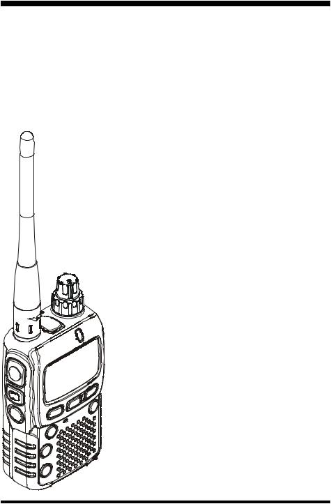
The VX-2R is a micro-miniature multiband FM transceiver with extensive receive frequency coverage, providing lo- cal-area two-way amateur communications along with unmatched monitoring capability.
The VX-2R’s incredibly small size allows you to take it anywhere - hiking, skiing, or while walking around town - and its operating flexibility brings the user many avenues of operating enjoyment. Its incredibly tiny FNB-82LI Lithium-Ion Battery Pack provides up to 1½ Watts of transmit power on VHF, and 1 Watt on UHF. Besides 144and 430-MHz transceive operation, the VX-2R provides receive coverage of the AM (MF) and FM broadcast bands, HF Shortwave Bands, VHF and UHF TV bands, the VHF AM aircraft band, and a wide range of commercial and public safety frequencies!
Additional features include a convenient access key for Vertex Standard’s WIRESTM (Wide-Coverage Internet Repeater Enhancement System), a transmit Time-Out Timer (TOT), Automatic Power-Off (APO), Automatic Repeater Shift (ARS), Yaesu’s exclusive ARTSTM (Auto-Range Transponder System) which “beeps” the user when you move out of communications range with another ARTSTM equipped station, plus provision for reduction of the TX deviation in areas of high channel congestion. And an RF squelch circuit allows the owner to set the squelch to open at a programmable setting of the S-Meter, thus reducing guesswork in setting the squelch threshold.
We appreciate your purchase of the VX-2R, and encourage you to read this manual thoroughly, so as to learn about the many exciting features of your exciting new Yaesu hand-held transceiver!
VX-2R OPERATING MANUAL |
1 |

CONTROL & CONNECTIONS
ANTENNA
Connect the supplied rubber flex antenna (or another antenna presenting a 50-Ohm impedance) here.
PTT (Push To Talk)
Press this switch to transmit, and release it (to receive) after your transmission is completed.
MONI
Pressing this key disables the noise squelching action, allowing you to hear very weak signals n e a r t h e b a c k - ground noise level.
POWER
Press and hold in this switch for one second to toggle the transceiver’s power on and off.
KEYPAD
These seven keys select many of most important operating features on the VX2R. The functions of the keys are described in detail on the pages to follow.
MIC/SP
This four-conductor miniature jack provides connection points for microphone audio, earphone audio, PTT, and ground.
VOLUME
This control adjusts the audio volume level. Clockwise rotation increases the volume level.
DIAL
The main tuning Dial is used for setting the operating frequency, and also is used for menu selections and other adjustments.
BUSY/TX
This indicator glows green when the squelch opens, and turns red during transmit . During “Emergency” operation See page 31, this indicator will glow (or flash) white.
EXT DC
This coaxial DC jack allows connection to a n e x t e r n a l D C power source (3.2- 7.0V DC). The center pin of this jack is the Positive (+) connection.
MIC
The internal microphone is located here.
SPEAKER
T h e i n t e r n a l speaker is located here.
2 |
VX-2R OPERATING MANUAL |
CONTROL & CONNECTIONS
KEYPAD FUNCTIONS
Key |
Press Key |
[BAND] Key Moves operation to the next-highest frequency band.
Activates the “Memory Bank” feature while in the Memory Recall mode.
[H/L] Key Switches the transmit power output between “HI” and “LOW.”
[V/M] Key Switches frequency control between the VFO and Memory Systems.
[F/W] Key
[HM/RV] Key
[ ] Key
] Key
Activates the “Alternate” key function.
Reverses the transmit and receive frequencies while working through a repeater.
Activates the WIRESTM (Internet Connection) feature.
[MD] Key Switches the operating mode.
Press + [F/W] Key
Moves operation to the next-lowest frequency band.
Selects the synthesizer steps to be used during VFO operation.
Activates the “Memory Tune” function while in the Memory Recall mode.
Disables the “Alternate” key function.
Switches operation to the “Home” (favorite frequency) channel.
Recalls the “Weather Broadcast” channels and Short-wave broadcast station channels.
Activates CTCSS or DCS operation.
Press and Hold Key
Activates the Scanner.
Enters the Set (Menu)
Mode.
Activates the Dual Watch feature.
Activates the “Memory Write” mode (for memory channel storage).
Activates the “Emergency” Function. See page 31.
Activates the ARTSTM feature.
Activates the Smart SearchTM and Channel Counter features.
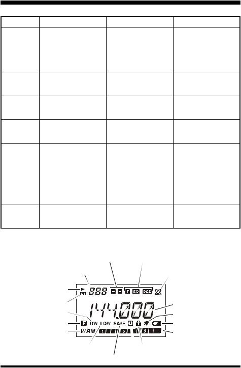
LCD DISPLAY
Repeater Shift Direction |
CTCSS/DCS Operation |
Operating Band Number or |
|
Memory Channel Number |
Internet Connection Feature Active |
Skip Memory Channel or |
|
Preferential Memory Channel |
|
Priority Channel |
Operating Frequency |
|
|
Dual Watch Active |
Bell Alerm Active |
|
|
Alt. Keypad Active |
Battery Indicator |
Operating Mode |
S- & PO Meter |
|
|
Low TX Power Selected |
Key Lock Active |
Battery Saver Active |
Automatic Power-Off Active |
VX-2R OPERATING MANUAL |
3 |
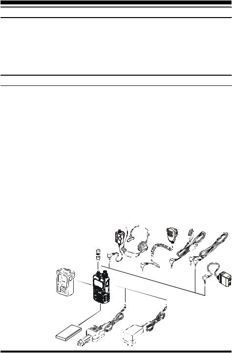
ACCESSORIES & OPTIONS |
|
|
|
SUPPLIED ACCESSORIES |
|
FNB-82LI |
3.7 V, 1000 mAh Rechargeable Lithium Ion Battery Pack .......... |
1 |
NC-85B, C, or Uø |
2.5-Hour Charger ...................................................................... |
1 |
Belt Clip ..................................................................................................................... |
|
1 |
Antenna ...................................................................................................................... |
|
1 |
Operating Manual ........................................................................................................ |
|
1 |
Warranty Card ............................................................................................................. |
|
1 |
|
AVAILABLE OPTIONS |
|
• CSC-90 |
Soft Case |
|
‚ CN-3 |
BNC-to-SMA Adapter |
|
ƒ VC-25 |
VOX Headset |
|
„ MH-34B4B |
Speaker/Microphone |
|
… MH-37A4B |
Ear piece/Microphone |
|
† CT-27 |
Cloning Cable |
|
‡ CT-44 |
Microphone Adapter |
|
ˆ FNB-82LI |
3.7 V, 1000 mAh Rechargeable Lithium Ion Battery Pack |
|
‰ E-DC-21 |
DC Cable w/Cigarette-Lighter Adapter |
|
Š NC-85B, C, Uø |
2.5-Hour Charger |
|
ø: “B” suffix is for use with 120 VAC, “C” suffix is for use with 230-240 VAC, and “U” suffix is for use with 230 VAC.
Availability of accessories may vary. Some accessories are supplied as standard per local requirements, while others may be unavailable in some regions. Consult your Yaesu dealer for details regarding these and any newly-available options Connection of any non-Yaesu- approved accessory, should it cause 

damage, may void the Limited War- |
|
ƒ „ |
… |
ranty on this apparatus. |
|
|
|
‚ |
|
|
† |
|
|
|
‡ |
• |
|
|
|
|
‰ |
Š |
|
ˆ |
|
|
|
|
|
|
4 |
VX-2R OPERATING MANUAL |
INSTALLATION OF ACCESSORIES
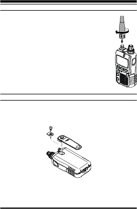
ANTENNA INSTALLATION
The supplied antenna provides good results over the entire frequency range of the transceiver. However, for enhanced base station medium-wave and shortwave reception, you may wish to connect an external (outside) antenna, as the supplied antenna is very small and cannot be expected to provide high performance at these frequencies.
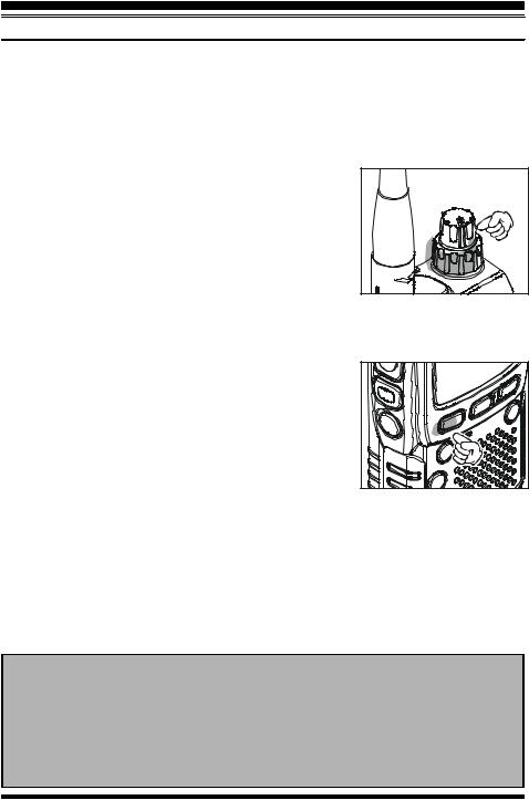
To install the supplied antenna, hold the bottom end of the antenna, then screw it onto the mating connector on the transceiver until it is snug. Do not over-tighten by use of extreme force.
Notes:
¦ Never transmit without having an antenna connected.
¦ When installing the supplied antenna, never hold the upper part of the antenna while screwing it onto the mating connector on the transceiver.
¦ If using an external antenna for transmission, ensure that the SWR presented to the transceiver is 1.5:1 or lower, to avoid excessive feedline loss.
INSTALLATION OF THE SUPPLIED BELT CLIP
1.Remove the dummy cover and its screw from the rear panel of the transceiver. Keep the dummy cover and screw in case you need to replace them in the future.
2.Connect the supplied Belt Clip, along with its mounting screw, to the rear panel.
Do not use the Belt Clip screw to affix the dummy cover!
VX-2R OPERATING MANUAL |
5 |
INSTALLATION OF ACCESSORIES
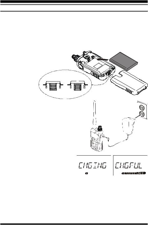
INSTALLATION OF FNB-82LI BATTERY PACK
The FNB-82LI is a high-performance Lithium-Ion battery providing high capacity in a very compact package. Under normal use, the FNB-82LI may be used for approximately 300 charge cycles, after which operating time may be expected to decrease. If you have an old battery pack which is displaying capacity which has become diminished, you should replace the pack with a new one.
Installation of the battery is easy and quick: |
|
||
r Slide the Battery Cover Latch to the |
|
||
Unlock position, then slide the Battery |
|
||
Cover toward the bottom to remove it. |
|
||
r Install the FNB-82LI into the Battery |
|
||
Compartment. |
|
|
|
r Replace the Bat- |
UNLOCK |
LOCK |
|
tery Cover, then |
á |
||
|
|||
|
σLOCK |
||
slide the Battery |
|
||
|
|
||
Cover Latch to |
á |
|
|
|
|
||
the Lock position.
If the battery has never been used, or its charge is depleted, it may be charged by connecting the NC-85 Battery Charger, as shown in the illustration, to the EXT DC jack. If only 12 ~ 16 Volt DC power is available, the optional E-DC-21 DC Adapter (with its cigarette lighter plug) may also be used for charging the battery.
While the battery is being charged, the display will indicate “CHGING” and the BUSY/TX indicator will
glow red. The S-meter will deflect according to the charging status. When charging is finished, the display will change to indicate “CHGFUL” and the BUSY/TX indicator will glow green.
Should you connect the NC-85 to the VX-2R without having the battery inside, the display will indicate “FL/NBT” to notify you that you need to install the battery. Similarly, if you connect the NC-85 to the VX-2R when the battery is fully charged, the display will indicate “CHGFUL,” the same display that you see at the end of the charge cycle.
The NC-85 is only designed for the charging of the VX-2R’s battery, and is not suitable for other purposes. Please be advised that the NC-85 may contribute noise to TV and radio reception in the immediate vicinity, so we do not recommend its use adjacent to such devices.
6 |
VX-2R OPERATING MANUAL |
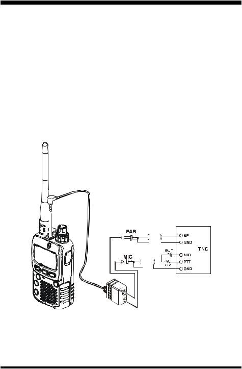
INTERFACE OF PACKET TNCS
The VX-2R may be used for Packet operation, using the optional CT-91 microphone adapter (available from your Yaesu dealer) for easy interconnection to commonly-available connectors wired to your TNC. You may also build your own cable, using a four-conductor miniature phone plug, per the diagram below.
The audio level from the receiver to the TNC may be adjusted by using the VOLUME knob, as with voice operation. The input level to the VX-2R from the TNC should be adjusted at the TNC side; the optimum input voltage is approximately 5 mV at 2000 Ohms.
Be sure to turn the transceiver and TNC off before connecting the cables, so as to prevent voltage spikes from possibly damaging your transceiver.
When you are operating on Packet, switch the Receive Battery Saver OFF, as the “sleep” cycle may “collide” with the beginning of an incoming Packet transmission, causing your TNC not to receive the full data burst. See page 32 for details regarding Battery Saver setup.
VX-2R OPERATING MANUAL |
7 |
OPERATION
Hi! I’m R. F. Radio, and I’ll be helping you along as you learn the many features of the VX-2R. I know you’re anxious to get on the air, but I encourage you to read the “Operation” section of this manual as thoroughly as
possible, so you’ll get the most out of this fantastic new transceiver. Now. . .let’s get operating!
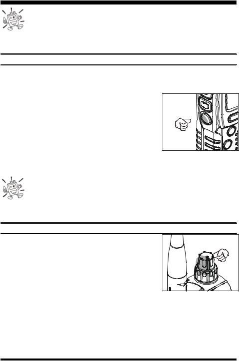
SWITCHING POWER ON AND OFF
1.Be sure the Battery Pack is installed, and that the battery is fully charged. Connect the antenna to the top panel ANTENNA jack.
2.Press and hold in the POWER switch (on the left side of the transceiver) for one
second. Two beeps will be heard when the switch has
been held long enough, and the current DC supply voltage will indicated on the display for 2 seconds; if you are using the FNB-82LI Battery Pack, the small “Lit” icon at the top of the display confirms that the LithiumIon Battery Pack has been detected. After this 2-sec- ond interval, the display will resume its normal indication of the operating frequency.
3. To turn the VX-2R off, press and hold in the POWER switch again for one second.
1) If you don’t hear the two “Beep” tones when the radio comes on, the Beeper may have been disabled via the Menu system. See page 14, which tells you how to reactivate the Beeper.
2) You can change the Opening Message (DC supply voltage indication) to any desired message (up to 6 characters) via Set Mode Item 30: OPNMSG; see page 68 for details.
ADJUSTING THE VOLUME LEVEL
Rotate the VOLUME control (inner knob) to set the desired audio level. Clockwise rotation increases the volume level.
8 |
VX-2R OPERATING MANUAL |
OPERATION
SQUELCH ADJUSTMENT
The VX-2R’s Squelch system allows you to mute the background noise when no signal is being received. Not only does the Squelch system make “standby” operation more pleasant, it also significantly reduces battery current consumption.
The Squelch system may be adjusted independently for the FM and Wide-FM (FM Broadcast) modes.
1.Press the [F/W] key, then press the MONI switch on the left side of the radio. This provides a “Short-cut” to Set Mode Item 41: SQL.
2.Now, rotate the DIAL knob to set the Squelch so that the background noise is just silenced (typically at a setting of about “1” or “2” for FM, and “2” or “3” for WideFM); this is point of maximum sensitivity to weak signals.
3.When you are satisfied with the Squelch threshold setting, press the PTT key momentarily to save the new setting and exit to normal operation.
1) A special “RF Squelch” feature is provided on the VX-2R. This feature allows you to set the squelch so that only signals exceeding a certain S-meter level will open the squelch. See page 17 for details.
2) If you’re operating in an area of high RF pollution, you may need to consider “Tone Squelch” operation using the built-in CTCSS Decoder. This feature will keep your radio quiet until a call is received from a station sending a carrier which contains a matching (subaudible) CTCSS tone. Or, if your friends have radios equipped with DCS (Digital Coded Squelch) like your VX-2R has, try using that mode for silent monitoring of busy channels.
VX-2R OPERATING MANUAL |
9 |
OPERATION
SELECTING THE OPERATING BAND
The VX-2R covers an incredibly wide frequency range, over which a number of different operating modes are used. Therefore, the VX-2R’s frequency coverage has been divided into different operating bands, each of which has its own pre-set channel steps and operating modes. You can change the channel steps and operating modes later, if you like (see page 15).
BAND |
|
FREQUENCY RANGE |
|
|
|
[BAND NUMBER] |
|
USA VERSION |
EXP VERSION |
||
BC Band |
[1] |
0.5 - 1.8 MHz |
0.504 - 1.8 MHz |
||
SW Band |
[2] |
1.8 - 30 MHz |
1.8 - 30 MHz |
||
50 MHz Ham Band |
[3] |
30 - 59 MHz |
30 - 88 MHz |
||
FM BC Band |
[4] |
59 |
- 108 MHz |
88 |
- 108 MHz |
Air Band |
[5] |
108 |
- 137 MHz |
108 |
- 137 MHz |
144 MHz Ham Band [6] |
137 |
- 174 MHz |
137 |
- 174 MHz |
|
VHF-TV Band |
[7] |
174 |
- 222 MHz |
174 |
- 222 MHz |
Action Band 1 |
[8] |
222 |
- 420 MHz |
222 |
- 420 MHz |
430 MHz Ham Band [9] |
420 |
- 470 MHz |
420 |
- 470 MHz |
|
VHF-TV Band |
[A] |
470 |
- 800 MHz |
470 |
- 800 MHz |
Action Band 2 |
[b] |
803 |
- 999 MHz |
800 |
- 999 MHz |
To Change Operating Bands:
1. Press the [BAND] key repetitively. You will see the LCD indication move toward a higher frequency band each time you press the [BAND] 


 key.
key. 


 2. If you wish to move the operating band selection down-


 ward (toward lower frequencies), press the [F/W] key


 first, then press the [BAND] key.


3. Once you have selected the desired band, you may initiate manual tuning (or scanning) per the discussion in the next chapter.
When receiving in the AM Broadcast or Shortwave bands (0.5-30 MHz), we recommend that you connect an external antenna, for improved reception.
10 |
VX-2R OPERATING MANUAL |
OPERATION
FREQUENCY NAVIGATION
The VX-2R will initially be operating in the “VFO” mode, a channelized system which allows free tuning throughout the currently-selected operating band.
Two basic frequency navigation methods are available on the VX-2R:
1) Tuning Dial (Outer ring of dual control on Top Panel)
Rotation of the DIAL allows tuning in the pre-programmed steps established for the current operating band. Clockwise rotation of the DIAL causes the
VX-2R to be tuned toward a higher frequency, while counterclockwise rotation will lower the operating frequency.
If you press the [F/W] key momentarily, then rotate the DIAL, frequency steps of 1 MHz will be selected. This feature is extremely useful for making rapid frequency excursions over the wide tuning range of the VX-2R.
2) Scanning
From the VFO mode, press and hold in the [BAND] key for one second, and rotate the
DIAL knob while holding in the [BAND] key to select the bandwidth for the VFO scanner, then release the [BAND] key to begin scanning toward a higher frequency. The scanner will stop when it receives a signal strong enough to break through the Squelch threshold. The VX-2R will then hold on that frequency according to the setting of the “RESUME” mode (Set Mode Item 31: RESUME). See page 47 for details regarding Scan Operatin.
If you wish to reverse the direction of the scan (i.e. toward a lower frequency, instead of a higher frequency), just rotate the DIAL one click in the counter-clockwise direction while the VX-2R is scanning. The scanning direction will be reversed. To revert to scanning toward a higher frequency once more, rotate the DIAL one click clockwise.
Press the PTT switch momentarily to cancel the scanning. This only stops the scan; it does not cause transmission to occur.
Notice
The VX-2R may receive very strong signals on the Image frequency. If you experience interference that you suspect may be coming in via an “Image” path, you may calculate the possible frequencies using the formulas below. This information may be used in the design of effective countermeasures such as traps, etc.
¦ 3.579545 MHz x n |
¦ 11.7 MHz x n |
(n is an integer: 1, 2, 3, …) |
VX-2R OPERATING MANUAL |
11 |
OPERATION
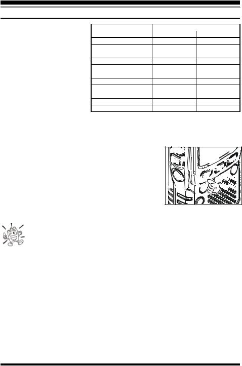
TRANSMISSION
Once you have set up an appropriate frequency inside one of the 144 MHz or 430 MHz Amateur bands on which the VX-2R can transmit, you’re ready to go on the air! These are the most basic steps; more advanced aspects of transmitter operation will be discussed later.
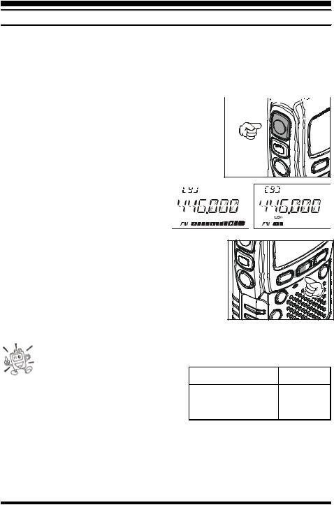
1.To transmit, press the PTT switch, and speak into the front panel microphone (located in the upper left-hand corner of the speaker grille) in a 
normal voice level. The BUSY/TX indicator will glow red during transmission.
2. To return to the receive mode, release the PTT switch.
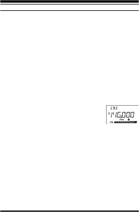
3. During transmission, the relative power level will be indicated on the bar graph at the bottom of the LCD; full scale deflection confirms “High Power” operation, while deflection of two bars indicates 
“Low Power” operation. Additionally, the
“LOW” icon will appear at the bottom of the display while operating on the
“Low Power” setting.
4. If you’re just talking to friends in the immediate area, you’ll get much longer battery life by switching to Low Power operation. To do this, press the [H/L] key so that the “LOW” icon appears at the bottom of the display. And don’t forget: always have an antenna connected when you transmit.
Transmission is possible only on the 144 MHz and 430 MHz bands.
The VX-2R is smart! You can set up Low power on 144 MHz band, while leaving 430 MHz on High power, and the radio will remember the different
settings on both bands. And when you |
BAND |
FNB-82LI |
EXT DC |
|
store memories, you can store High and Low |
(3.7 V) |
(6.0 V) |
||
|
||||
144 MHz |
HI: 1.5 W |
HI: 3.0 W |
||
power settings separately in each memory, so you |
||||
|
LOW: 0.1 W |
LOW: 0.3 W |
||
don’t waste battery power when using very close- 430 MHz |
HI: 1.0 W |
HI: 2.0 W |
||
in repeaters! |
|
LOW: 0.1 W |
LOW: 0.3 W |
|
|
|
|
||
2) When you are operating on the Low power setting, you can press the [F/W] key, when press the PTT switch, to cause the VX-2R to transmit (temporarily) on High power. After one transmission, the power level will revert to the previously-selected (Low power) setting.
12 |
VX-2R OPERATING MANUAL |
OPERATION
KEYBOARD LOCKING
In order to prevent accidental frequency change or inadvertent transmission, various aspects of the VX-2R’s keys and switches may be locked out. The possible lockout combinations are:
KEY: Just the front panel keys are locked out
DIAL: Just the top panel DIAL is locked out
K+D: Both the DIAL and Keys are locked out
PTT: The PTT switch is locked (TX not possible)
K+P: Both the keys and PTT switch are locked out
D+P: Both the DIAL and PTT switch are locked out
ALL: All of the above are locked out
To lock out some or all of the keys:
1.Press and hold in the [H/L] key for one second to enter the Set mode.
2.Rotate the DIAL knob to select Set Mode Item 25: LOCK.
3.Press the [H/L] key momentarily to enable adjustment of this Item.
4.Rotate the DIAL knob to choose between one of the locking schemes as outlined above.
5.When you have made your selection, press the PTT key to save the new setting and return to normal operation.
To activate the locking feature, press the [F/W] key, then press and hold in the [BAND] key for one second. The “ ” icon will appear on the LCD. To cancel locking, repeat this process.
VX-2R OPERATING MANUAL |
13 |
OPERATION
KEYPAD/LCD ILLUMINATION
Your VX-2R includes a reddish illumination lamp which aids in nighttime operation. The red illumination yields clear viewing of the display in a dark environment, with minimal degradation of your night vision. Three options for activating the lamp are provided:
KEY Mode: Illuminates the Keypad/LCD for five seconds when any key pressed. CONT Mode: Illuminates the Keypad/LCD continuously.
OFF Mode: Disables the Keypad/LCD lamp.
Here is the procedure for setting up the Lamp mode:
1.Press and hold in the [H/L] key for one second to enter the Set mode.
2.Rotate the DIAL knob to select Set Mode Item 24: LAMP.
3.Press the [H/L] key momentarily to enable adjustment of this Item.
4.Rotate the DIAL knob to select one of the three modes described above.
5.When you have made your choice, press the PTT key to save the new setting and return to normal operation.
You may also adjust the Keypad/LCD illumination level and LCD contrast by use of the Set Mode. See page 16 for details.
DISABLING THE KEYPAD BEEPER
If the keypad’s Beeper creates an inconvenience (particularly when operating in a quiet room), it may easily be disabled.
1.Press and hold in the [H/L] key for one second to enter the Set mode.
2.Rotate the DIAL knob to select Set Mode Item 7: BEEP.
3.Press the [H/L] key momentarily to enable adjustment of this Item.
4.Rotate the DIAL knob to change the setting from ON to OFF.
5.When you have made your selection, press the PTT key to save the new setting and return to normal operation.
6.If you wish to re-enable the Beeper, just repeat the above procedure, rotating the DIAL knob to select ON in step “4” above.
14 |
VX-2R OPERATING MANUAL |
-
Now that you’re mastered the basics of VX-2R operation, let’s learn more about some of the really neat features.
CHECKING THE BATTERY VOLTAGE
The VX-2R’s microprocessor includes programming which will detect the battery type and measure the current battery voltage.
1. Press and hold in the [H/L] key for one second to enter the Set mode.
2. Rotate the DIAL knob to select Set Mode Item 13: DC VLT.
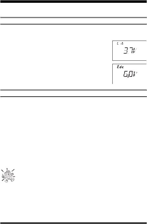
3.Press the [H/L] key momentarily to display the battery type and the current DC voltage being supplied.
Lit: FNB-82LI is in use.
Edc: An external DC source is in use.
4.Press and hold in the [H/L] key for one second to return to normal operation.
CHANGING THE CHANNEL STEPS
The VX-2R’s synthesizer provides the option of utilizing channel steps of 5/9/10/12.5/15/ 20/25/50/100 kHz per step, as well as an automatic step selection based on the current operating frequency (“AUTO”), any number of which may be important to your operating requirements. The VX-2R is set up at the factory in the “AUTO” configulation, which probably is satisfactory for most operation. However, if you need to change the channel step increments, the procedure to do so is very easy.
1.Press and hold in the [H/L] key for one second to enter the Set mode.
2.Rotate the DIAL knob to select Set Mode Item 43: STEP.
3.Press the [H/L] key momentarily to enable adjustment of this Item.
4.Rotate the DIAL knob to select the new channel step size.
5.When you have made your selection, press the PTT key to save the new setting and return to normal operation.
1)9 kHz steps are available only when receiving on the BC band.
2)While operating on the BC band, you may only select channel steps of 9 kHz or 10 kHz; the other step selections are disabled.
3) 5 kHz steps are not available for use on 250 - 300 MHz, nor above 530 MHz.
VX-2R OPERATING MANUAL |
15 |

ADVANCED OPERATION
CHANGING THE RECEIVING MODE
The VX-2R provides for automatic mode changing when the radio is tuned to different operating frequencies. However, should an unusual receiving situation arise in which you need to change other receiving mode, just press the [MD] key. The receiving modes available are:
AUTO: Automatic mode setting per default values for the selected frequency range. N-FM: Narrow-bandwidth FM (used for voice communication)
W-FM: Wide-bandwidth FM (used for high-fidelity broadcasting) AM: Amplitude Modulation
Unless you have a compelling reason to do so, leave the Automatic Mode Selection feature on so as to save time and trouble when changing bands. If you make a mode change for a particular channel or station, you can always
store that one channel into memory, as the mode setting will be memorized along with the frequency information.
DISPLAY DIMMER
The LCD and keypad illumination level may be adjusted using the Set Mode.
1.Press and hold in the [H/L] key for one second to enter the Set mode.
2.Rotate the DIAL knob to select Set Mode Item 16: DIMMER.
3.Press the [H/L] key momentarily to enable adjustment of this Set Mode Item.
4.Rotate the DIAL knob to adjust the display illumination for a comfortable brightness level. As you make the adjustment, you will be able to see the effects of your changes.
5.When you have completed the adjustment, press the PTT key to save the new setting and exit to normal operation.
16 |
VX-2R OPERATING MANUAL |

ADVANCED OPERATION
RF SQUELCH
A special RF Squelch feature is provided on this radio. This feature allows you to set the squelch so that only signals exceeding a certain S-meter level will open the squelch.
To set up the RF squelch circuit for operation, use the following procedure:
1.Press and hold in the [H/L] key for one second to enter the Set mode.
2.Rotate the DIAL knob to select Set Mode Item 32: RF SQL.
3.Press the [H/L] key momentarily to enable adjustment of this Item.
4.Rotate the DIAL knob to select the desired signal strength level for the squelch threshold (S1, S2, S3, S4, S5, S6, S8, S9+, or OFF).
5.Press the PTT key to save the new setting and return to normal operation.
The receiver’s squelch will open based on the higher of the levels set by the two squelch systems (Noise Squelch and RF Squelch).
For example:
1)If the Noise Squelch (SQL control) is set so that signals at a level of S-3 will open the squelch, but the RF Squelch (Set Mode Item 32) is set to “S5,” the squelch will only open on signals which are “S-5” or stronger on the S-meter.
2)If the RF Squelch is set to “S3,” but the Noise Squelch is set to a high level which will only pass signals which are Full Scale on the S-meter, the squelch will only open on signals which are Full Scale on the S-meter. In this case, the Noise Squelch overrides the action of the RF Squelch.
VX-2R OPERATING MANUAL |
17 |
ADVANCED OPERATION
REPEATER OPERATION
Repeater stations, usually located on mountaintops or other high locations, provide a dramatic extension of the communication range for low-powered hand-held or mobile transceivers. The VX-2R includes a number of features which make repeater operation simple and enjoyable.
Repeater Shifts
Your VX-2R has been configured, at the factory, for the repeater shifts customary in your country. For the 144 MHz band shift will be 600 kHz; on the 430 MHz band, the shift may be 1.6 MHz, 7.6 MHz, or 5 MHz (USA version).
Depending on the part of the band in which you are operating, the repeater shift may be either downward ( ) or upward (
 ), and one of these icons will appear at the top of the LCD when repeater shifts have been enabled.
Automatic Repeater Shift (ARS)
The VX-2R provides a convenient Automatic Repeater Shift feature, which causes the appropriate repeater shift to be applied automatically whenever you tune into the designated repeater sub-bands in your country. These sub-bands are shown below.
If the ARS feature does not appear to be working, you may have accidentally disabled it.
To re-enable ARS:
1.Press and hold in the [H/L] key for one second to enter the Set mode.
2.Rotate the DIAL knob to select Set Mode Item 4: ARS.
3.Press the [H/L] key momentarily to enable adjustment of this Item.
4.Rotate the DIAL knob to select “ON” (to enable Automatic Repeater Shift).
5.When you have made your selection, press the PTT key to save the new setting and return to normal operation.
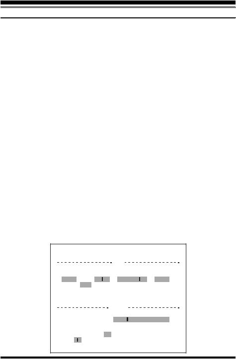
ARS-Repeater Subbands
2-m Version A
145.1 |
145.5 |
146.0 |
|
146.4 |
|
|
|
147.0 |
|
147.6 |
|
148.0 |
||||||||||||||||||||
|
|
|
|
|
|
|
|
|
|
|
|
|
|
|
|
|
|
|
|
|
|
|
|
|
|
|
|
|
|
|
|
|
|
|
|
|
|
|
|
|
|
|
|
|
|
|
|
|
|
|
|
|
|
|
|
|
|
|
|
|
|
|
|
|
|
|
|
|
|
|
|
|
|
|
|
|
|
|
146.6 |
|
|
|
|
|
|
147.4 |
|
|
|
|
|
|
||||||
|
|
|
|
|
|
|
|
|
|
|
|
|
|
|
|
|
|
|
|
|
|
|||||||||||
|
|
145.6 145.8 |
|
|
|
|
|
|
|
|
|
|
|
|
|
|
|
|
|
|
|
|
|
|||||||||
|
|
|
|
|
|
|
|
|
|
|
European Version |
|
|
|
|
|
|
|
|
|||||||||||||
|
|
|
|
|
|
|
|
|
|
|
|
|
|
|
70-cm |
|
|
|
|
|
|
|
|
|
|
|
|
|||||
Version A |
440.0 |
|
|
445.0 |
|
|
|
|
|
450.0 |
||||||||||||||||||||||
|
|
|
|
|
|
|
|
|
|
|
|
|
|
|
|
|
|
|
|
|||||||||||||
|
|
|
|
|
|
|
|
|
|
|
|
|
|
|
|
|
|
|
|
|
|
|
|
|
|
|
|
|
|
|
|
|
|
|
|
|
|
|
|
438.20 |
439.45 |
|
Euro Version 1 |
|
|
||||||||||||||||||||
|
|
|
|
|
|
|
|
|
|
|
|
|
|
|
|
|
|
|
|
|
|
|
||||||||||
|
|
|
|
|
|
|
|
|
|
|
|
|
|
|
|
|
|
|
|
|
|
|
|
|
|
|
|
|
|
|
|
|
433.00 |
|
|
|
433.40 Euro Version 2 |
|
|
|
|
|
|
|
|
||||||||||||||||||||
|
|
|
|
|
|
|
|
|
|
|
||||||||||||||||||||||
18 |
VX-2R OPERATING MANUAL |
ADVANCED OPERATION
REPEATER OPERATION
Manual Repeater Shift Activation
If the ARS feature has been disabled, or if you need to set a repeater shift direction other than that established by the ARS, you may set the direction of the repeater shift manually.
To do this:
1.Press and hold in the [H/L] key for one second to enter the Set mode.
2.Rotate the DIAL knob to select Set Mode Item 33: RPT.
3.Press the [H/L] key momentarily to enable adjustment of this Item.
4.Rotate the DIAL knob to select the desired shift among “–RPT,” “+RPT,” and “SIMP.”
5.When you have made your selection, press the PTT key to save the new setting and return to normal operation.
If you make a change in the shift direction, but still have Automatic Repeater Shift still engaged (see previous section), when you change frequency (by rotating the DIAL knob, for example) the ARS will over-ride your manual
setting of the shift direction. Turn ARS off if you do not wish this to happen.
Changing the Default Repeater Shifts
If you travel to a different region, you may need to change the default repeater shift so as to ensure compatibility with local operating requirements.
To do this, follow the procedure below:
1.Set the VX-2R’s frequency to the band on which you wish to change the default repeater shift (144 MHz or 430 MHz Ham Band).
2.Press and hold in the [H/L] key for one second to enter the Set mode.
3.Rotate the DIAL knob to select Set Mode Item 38: SHIFT.
4.Press the [H/L] key momentarily to enable adjustment of this Item.
5.Rotate the DIAL knob to select the new repeater shift magnitude.
6.When you have made your selection, press the PTT key to save the new setting and return to normal operation.
If you just have one “odd” split that you need to program, don’t change the “default” repeated shifts using this Set Mode Item! Enter the transmit and receive frequencies separately, as shown on page 37.
VX-2R OPERATING MANUAL |
19 |

ADVANCED OPERATION
REPEATER OPERATION
Checking the Repeater Uplink (Input) Frequency
It often is helpful to be able to check the uplink (input) frequency of a repeater, to see if the calling station is within direct (“Simplex”) range.
To do this, just press the [HM/RV] key. You’ll notice that the display has shifted to the repeater uplink frequency. Press the [HM/RV] key again to cause operation to revert to normal monitoring of the repeater downlink (output) frequency.
The configuration of this key may be set either to “RV” (for checking the input frequency of a repeater), or “HM” (for instant switching to the “Home” channel for the band you are operating on). To change the configuration of
this key, use Set Mode Item 22: HM/RV. See page 67.
20 |
VX-2R OPERATING MANUAL |
ADVANCED OPERATION
CTCSS OPERATION
Many repeater systems require that a very-low-frequency audio tone be superimposed on your FM carrier in order to activate the repeater. This helps prevent false activation of the repeater by radar or spurious signals from other transmitters. This tone system, called “CTCSS” (Continuous Tone Coded Squelch System), is included in your VX-2R, and is very easy to activate.
CTCSS setup involves two actions: setting the Tone Frequency and then setting of the Tone Mode. These actions are set up by using the [MD] key or Set Mode Items 42: SQLTYP and 44: TN FRQ.
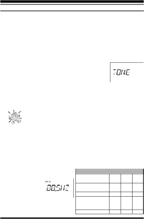
1. Press the [F/W] key, then press the [MD] key. This provides a “Short-cut” to Set Mode Item 42: SQLTYP.
2. Rotate the DIAL knob so that “TONE” appears on the display; this activates the CTCSS Encoder, which allows repeater access.
3. Rotation of the DIAL knob one more “click” in step “2” above will cause the “T SQL” notation to appear. When “T SQL” is displayed, this means that the Tone SQueLch system is active, which mutes your VX-2R’s receiver until it receives a call from another radio sending out a matching CTCSS tone. This can help keep your radio quiet until a specific call is received, which may be helpful while operating in congested.
1) You may notice an additional “DCS” icon appearing while you rotate the DIAL knob in this step. We’ll discuss the Digital Code Squelch system shortly.
2) You may notice “RV TN” indication on the display, this means that the Reverse Tone Squelch system is active, which mutes your VX-2R’s receiver when it receives a call from the radio sending a matched CTCSS tone. The “TSQ” icon will blink on the display when the Reverse Tone Squelch system is activated.
4. When you have made your selection of the CTCSS tone mode, press the PTT key to save the new setting.
5. Press and hold in the [H/L] key for one second to enter the Set mode. 6. Rotate the DIAL knob to select Set Mode Item 44: TN FRQ.
7. Press the [H/L] key momentarily to en-  able adjustment of the CTCSS frequency.
  8. Rotate the DIAL

knob until the display indicates the Tone Frequency
you need to be using (ask the repeater owner/operator if you don’t know the tone frequency).
VX-2R OPERATING MANUAL |
21 |
ADVANCED OPERATION
CTCSS OPERATION
9.When you have made your selection, press the [H/L] key momentarily, then press the PTT switch, to save the new settings and exit to normal operation. This is different than the usual method of restoring normal operation, and it applies only to the configuration of the CTCSS/DCS frequencies.
Your repeater may or may not re-transmit a CTCSS tone - some systems just use CTCSS to control access to the repeater, but don’t pass it along when transmitting. If the S-Meter deflects, but the VX-2R is not passing audio, repeat steps “1” through “4” above, but rotate the DIAL so that “TSQ” disappears - this
will allow you to hear all traffic on the channel being received.
DCS OPERATION
Another form of tone access control is Digital Code Squelch, or DCS. It is a newer, more advanced tone system which generally provides more immunity from false paging than does CTCSS. The DCS Encoder/Decoder is built into your VX-2R, and operation is very similar to that just described for CTCSS. Your repeater system may be configured for DCS; if not, DCS is frequently quite useful in Simplex operation if your friend(s) use transceivers equipped with this advanced feature.
Just as in CTCSS operation, DCS requires that you set the Tone Mode to DCS and that you select a tone code.
1.Press the [F/W] key, then press the [MD] key. This provides a “Short-cut” to Set Mode Item 42: SQLTYP.
2.Press the [H/L] key momentarily to enable adjustment of this Item.
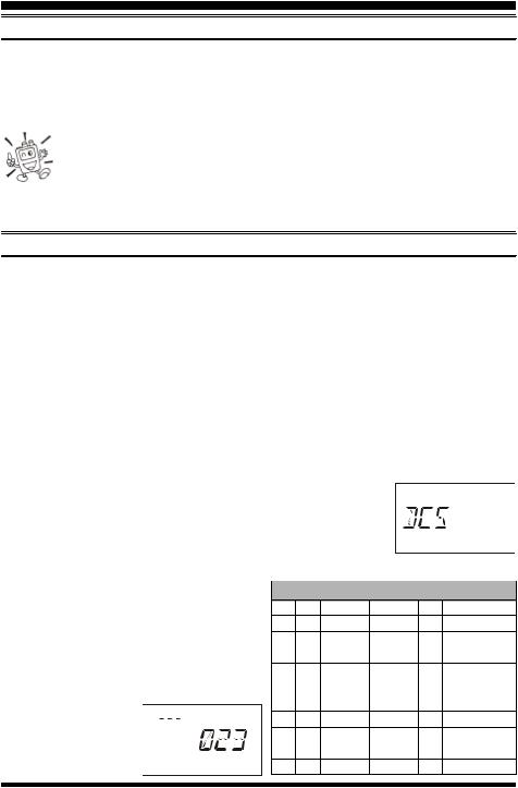
3.Rotate the DIAL knob until “DCS” appears on the display; this
activates the DCS Encoder/Decoder.
4. Press the PTT key to save the new setting.
5.Press and hold the [H/L] key for one second to enter the Set mode.
6.Rotate the DIAL knob to select Set Mode 
Item 14: DCS CD.
7.Press the [H/L] key momentarily to enable the adjustment of the DCS code.
8.Rotate the DIAL knob to select the desired DCS Code (a three-digit number). Ask the
repeater owner/operator if you don’t know DCS Code; if you 


are working simplex, just set up the DCS Code to be
DCS CODE
023 |
025 |
026 |
031 |
032 |
036 |
043 |
047 |
051 |
053 |
054 |
065 |
071 |
072 |
073 |
074 |
114 |
115 |
116 |
122 |
125 |
131 |
132 |
134 |
143 |
145 |
152 |
155 |
156 |
162 |
165 |
172 |
174 |
205 |
212 |
223 |
225 |
226 |
243 |
244 |
245 |
246 |
251 |
252 |
255 |
261 |
263 |
265 |
266 |
271 |
274 |
306 |
311 |
315 |
325 |
331 |
332 |
343 |
346 |
351 |
356 |
364 |
365 |
371 |
411 |
412 |
413 |
423 |
431 |
432 |
445 |
446 |
452 |
454 |
455 |
462 |
464 |
465 |
466 |
503 |
506 |
516 |
523 |
526 |
532 |
546 |
565 |
606 |
612 |
624 |
627 |
631 |
632 |
654 |
662 |
664 |
703 |
712 |
723 |
731 |
732 |
734 |
743 |
754 |
– |
– |
– |
– |
– |
– |
22 |
VX-2R OPERATING MANUAL |
 Loading...