


OPERATING MANUAL
VERTEX STANDARD CO., LTD.
4-8-8 Nakameguro, Meguro-Ku, Tokyo 153-8644, Japan
VERTEX STANDARD
US Headquarters
10900 Walker Street, Cypress, CA 90630, U.S.A.
YAESU EUROPE B.V.
P.O. Box 75525, 1118 ZN Schiphol, The Netherlands
YAESU UK LTD.
Unit 12, Sun Valley Business Park, Winnall Close
Winchester, Hampshire, SO23 0LB, U.K.
VERTEX STANDARD HK LTD.
Unit 5, 20/F., Seaview Centre, 139-141 Hoi Bun Road, Kwun Tong, Kowloon, Hong Kong

Contents
Introduction .......................................... |
1 |
Supplied Accessories .................................. |
1 |
Available Option ......................................... |
1 |
Front Panel Controls & Switches........ |
2 |
Rear Panel Connections ....................... |
6 |
Installation............................................. |
8 |
Power connections ...................................... |
8 |
Antenna considerations............................... |
9 |
Basic Operation .................................. |
14 |
Introduction .............................................. |
14 |
Turning the Power On/Off ........................ |
14 |
Adjusting the Volume and Squelch .......... |
14 |
Frequency Navigation ............................... |
14 |
Mode Selection ......................................... |
15 |
Channel Step Selection ............................. |
16 |
Dual Receive ............................................. |
16 |
Setting the clock ....................................... |
17 |
Receiving Short-Wave Broadcast Stations ... |
18 |
Memory Operation ............................. |
20 |
Main Memory System .............................. |
20 |
Memory Storage .................................... |
20 |
Memory Recall ...................................... |
20 |
Enhanced Memory Channel Operation .... |
22 |
Memory Offset Tuning ......................... |
22 |
Naming Memories................................. |
22 |
Naming Memory Groups ...................... |
24 |
Protecting Memories (Inhibits the |
|
Editing of Memorized Channels).... |
24 |
Masking Memories ............................... |
25 |
Alpha-Numeric Memory Recall ............ |
26 |
Programmable Memory Recall ................. |
26 |
Memory Channel Sort............................... |
28 |
PS (PreSet) Memory Channel................... |
29 |
Scanning .............................................. |
30 |
Memory Scanning ..................................... |
32 |
VFO scanning ........................................... |
33 |
Programmable (Band Limit) |
|
Memory Scan (PMS) ... |
34 |
M-S Scan .................................................. |
36 |
Band Scope Operation ....................... |
37 |
Smart Search Operation .................... |
38 |
Priority Operation .............................. |
39 |
World Clock ........................................ |
40 |
Timer Operation ................................. |
42 |
ON/OFF Timer ......................................... |
42 |
Sleep Timer ............................................... |
43 |
Alarm Timer.............................................. |
43 |
DSP Operation .................................... |
44 |
DSP NOTCH Filter .................................. |
44 |
DSP Bandpass Filter ................................. |
44 |
DSP CW Peaking Filter ............................ |
45 |
DSP Noise Reduction ............................... |
46 |
CW-PITCH ............................................... |
46 |
Miscellaneous Features ...................... |
47 |
ATT (RF Attenuator) ................................ |
47 |
NB (Noise Blanker) .................................. |
47 |
RF TUNE .................................................. |
47 |
Keypad Beeper.......................................... |
47 |
Locking Front Panel Controls .................. |
48 |
Display Contrast ....................................... |
49 |
Display Dimmer ........................................ |
49 |
Selecting the [F] key “Hang” Time .......... |
49 |
Voice Synthesizer Operation .................... |
50 |
Digital Voice Recorder ............................. |
50 |
Field Strength Meter ................................. |
51 |
Audio Wave Meter ................................... |
52 |
Radio Control (R/C) Channel Monitoring .. |
52 |
Cloning................................................. |
53 |
CAT Operation................................. |
54 |
Reset ..................................................... |
56 |
Installation of the |
|
Optional Accessories ... |
57 |
“AUTO” Mode Preset |
|
Operationg Parameters .... |
58 |
Introduction
The VR-5000 is a communications receiver providing general coverage reception from 100 kHz to 2600 MHz on the CW, SSB (LSB and USB), AM, and FM (Wide and Narrow bandwidths) modes (this coverage includes the AM and FM broadcast bands, HF Shortwave Bands up to 16 MHz, VHF and UHF TV bands, the VHF AM aircraft band, and a wide range of commercial and public safety frequencies!).
Installation of the VR-5000 for everyday operation is may be accomplished in minutes. However, care should be taken in the installation process, so as to ensure maximum performance and safety. The procedures described below will ensure that you get the most out of your new VR-5000 receiver.
INITIAL INSPECTION
After carefully removing the VR-5000 from its packing carton, inspect it for any signs of physical damage. Rotate the knobs and push the switches, checking each for normal freedom of action. If damage is suspected, write down your observations in detail, and notify the shipping company (if the set was shipped to you) or your dealer (if you purchased the set in-person) immediately. Save the packing carton for possible use later.
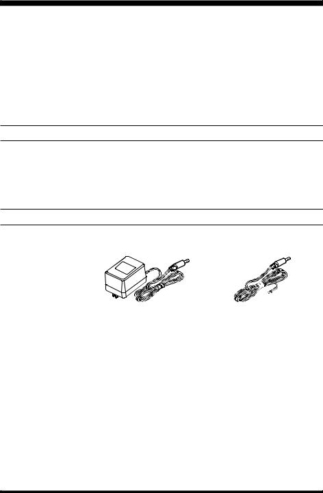
SUPPLIED ACCESSORIES
AC Adapter PA-28B (120 V)/C (230-240 V)/U (230 V)
DC Cable
Operating Manual
|
AC Adapter•gPA-28•h |
DC Cable |
|
|
|
|
AVAILABLE OPTIONS |
|
|
|
|
Voice Synthesizer Unit |
DSP-1 |
|
Voice Synthesizer Unit |
FVS-1A |
|
Digital Voice Memory Unit DVS-4
VR-5000 OPERATING MANUAL |
1 |
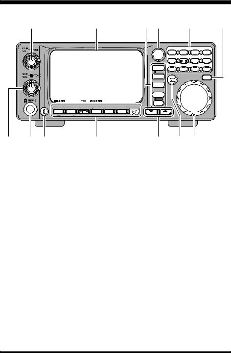
Front Panel Controls & Switches
‡@ |
‡D |
‡G‡F |
|
‡I |
‡K |
|
|
|
|
ATT |
LOCK S.SRCH SET |
||
|
|
PS |
1 |
2 |
3 |
ENT |
|
|
SPL |
PRI |
S.CALL BEEP |
||
|
|
|
||||
|
|
|
4 |
5 |
6 . |
|
|
|
ADRS |
VCS RF TUNE TIMER |
N B |
||
|
|
|
||||
|
|
MODE |
7 |
8 |
9 |
0 |
|
|
|
||||
|
|
REC |
|
|
|
|
|
|
COPY |
|
|
|
DSP |
|
|
|
|
|
|
|
|
|
PLAY |
|
|
|
|
|
|
STEP |
|
|
|
|
|
|
M W |
|
|
|
|
|
|
V / M |
|
|
|
|
BANK
PWR
 SUB SET BS SET BS STEP M-S SCAN PMS SET PRI CLR DIM
M/S |
B S |
SCAN |
PMS |
CLR |
‡A ‡B‡C |
‡E |
‡H ‡J ‡L |
MAIN VOL/SQL Knob
MAIN VOL Knob
The inner MAIN VOL knob adjusts the audio volume of the MAIN receiver in the speaker or headphones.
SQL Knob
The outer SQL knob sets the signal level threshold at which MAIN receiver audio is muted (and the “BUSY” icon in the LCD turns off), in all modes. This is normally kept fully counter-clockwise, except when scanning and during FM operation.
SUB VOL/TONE Knob
SUB VOL Knob
The inner SUB VOL knob adjusts the audio volume of the SUB receiver in the speaker or headphones.
TONE Knob
The outer TONE knob adjusts receiver audio characteristics.
PHONES Jack
This 3-pin (“stereo”) miniature jack is used for connection to your headphones. When a plug is inserted into this jack, the internal (or external) speaker will be cut off. This jack’s impedance is optimized for use with 16Ω to 32Ω headphone types.
2 |
VR-5000 OPERATING MANUAL |
Front Panel Controls & Switches
PWR Knob
This is the main on/off switch for the VR-5000. Press and hold this switch for one second to toggle the receiver’s power on and off.
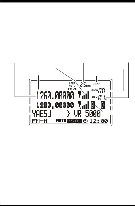
LCD (Liquid Crystal Display)
The upper half of the display consists of a dot-matrix display for frequency readout, plus various icons representing enabled receiver features.
The lower half contains a dot-matrix display for Band Scope viewing, menu programming, and alpha numeric name display, etc.
Main Band Frequency |
Main Band Channel Step |
Memory Channel Number |
|
Main Band S-Meter |
|
Memory Bank Number |
|
Main Band Reception Mode |
Main Band Scan-Resume |
||
|
|
|
|
|
|
|
|
|
|
|
|
|
|
|
|
|
|
|
|
|
|
|
|
|
|
|
|
|
|
|
|
|
|
|
|
|
|
|
|
|
|
|
|
|
|
|
|
|
|
|
|
|
|
|
|
|
|
|
|
|
|
|
|
|
|
|
|
|
|
|
|
|
|
|
|
|
|
|
|
|
|
|
|
|
|
|
|
|
|
|
|
|
|
|
|
|
|
|
|
|
|
|
|
|
|
|
|
|
|
|
|
|
|
|
|
|
|
|
|
|
|
|
|
|
|
|
|
|
|
|
|
|
|
|
|
|
|
|
|
|
|
|
|
|
|
|
|
|
|
|
|
|
|
|
|
|
|
|
|
|
|
|
|
|
|
|
|
|
|
|
|
|
|
|
|
|
|
|
|
|
|
|
|
|
|
|
|
|
|
|
|
|
|
|
|
|
|
|
|
|
|
|
|
|
|
|
|
|
|
|
|
|
|
|
|
|
|
|
|
|
|
|
|
|
|
|
|
|
|
|
|
|
|
|
|
|
|
|
|
|
|
|
|
|
|
|
|
|
|
|
|
|
|
|
|
|
|
|
|
|
|
|
|
|
|
Sub Band Reception Mode |
|
|
|
|
|
|
|
Clock Memory Name |
|
|
|||||||||||||||||||||||||||||||
|
|
|
|
|
|
|
|
|
|
|
|
|
|
|
|
|
|
|
|
|
|||||||||||||||||||||||
|
Bank Name |
|
Sub Band Channel Step |
|
|
|
|
|
|
Sub Band Squelch Open |
|
||||||||||||||||||||||||||||||||
|
|
|
|
|
|
|
|
|
|
|
|
|
|
|
|
|
|
|
|
|
|
|
|
|
|
|
|
|
|
|
|
|
|
|
|
|
|
|
|
||||
Sub Band Frequency |
|
|
|
|
|
|
|
|
|
|
|
|
|
|
|
|
|
|
|
|
|
|
|
|
|
|
|
|
|
Sub Band Scan-Resume |
|||||||||||||
Function Keys
 : DELAY SCAN
  : PAUSE SCAN
 : HOLD SCAN
[M/S(SUB SET)] Key
Press this key momentarily to toggle the operating VFO between the MAIN VFO and SUB VFO.
Press this key, after [F] key is pressed, to toggle the VFO link feature on and off.
[BS(BS SET)] Key
Press this key momentarily to toggle the Band Scope feature on and off.
Press this key twice, after the [F] key is pressed (when the Band Scope is activated) to activate the SUB VFO cursor, which enables SUB VFO tuning.
VR-5000 OPERATING MANUAL |
3 |

Front Panel Controls & Switches
[WIDTH(BS STEP)] Key
Press this key momentarily to select the Band Scope sweep width.
Press this key after [F] key is pressed (when the Band Scope is activated) to select the Band Scope sweeping step size.
[SCAN(M-S SCAN)] Key
Press this key momentarily to activate the scanning function.
Press this key after [F] key is pressed to activate the “M-S Scanning” feature.
M-S Scan: The scanner hops back and forth between the MAIN VFO frequency and SUB VFO frequency.
[PMS(PMS SET)] Key
Press this key momentarily to activate the Programmable Memory Scan feature. Press this key after [F] key is pressed to enable PMS memory (band edge) programming. PMS Scan: The scanner sweeps a user-defined subband of frequencies (e.g. 450-480 MHz).
[CLR(PRI CLR)] Key
Press this key momentarily to clear (cancel) the function you currently are programming.
Press this key after [F] key is pressed to disable Priority Channel operation. [V(DIM)] Key
Press this key momentarily to enable adjustment of the display brightness.
Press this key after [F] key is pressed to activate the optional FVS-1A Voice Synthesizer Unit which provides announcement of the operating frequency (with resolution to the displayed 100 Hz digit) for operators with vision impairments.
PS Key
Press this key momentarily to recall one of up to five PS (PreSet) memories for operation.
Press and hold this key for one second to store the operating parameters into consecutive PS memories.
Command Keys
[MODE(ADRS)] Key
Press this key momentarily to select the operating (receiving) mode. Repeated pressing of this key will scroll you through the available receiving mode choices.
Press this key after [F] key is pressed to select the recording field (memory register) for the voice recorder (requires the optional DVS-4 Digital Voice Recorder unit).
[COPY(REC)] Key
Press this key momentarily to copy the SUB VFO data into the MAIN VFO. Press this key after [F] key is pressed to start the voice recorder.
4 |
VR-5000 OPERATING MANUAL |

Front Panel Controls & Switches
[STEP(PLAY)] Key
Press this key momentarily to select the synthesizer steps to be used during VFO operation.
Press this key after [F] key is pressed to initiate playback on the voice recorder.
[V/M(MW)] Key
Press this key momentarily to change the frequency control method between the VFO and the Memory systems.
Press this key after [F] key is pressed to initiate the memory storage process.
[BANK] Key
Press this key momentarily to select the desired memory bank.
( )/ ( ) Keys
In the VFO mode, pressing either of these keys momentarily steps (according to the DIAL knob’s step setting) the operating frequency down or up, respectively. Pressing either of these keys after [F] key is pressed causes a frequency hop of 10 MHz down or up.
In the Memory mode, pressing either of these keys momentarily steps the Memory Channel down or up respectively.
While the Band Scope is engaged, pressing either of these keys moves the Channel Marker.
Keypad
This keypad is used for direct frequency entry during VFO operation.
Secondary functions (activated by first pressing the [F] key) allow control of the VR5000’s various control functions.
11 [F] Key
This key is used to activate the “Alternate” command functions of the panel keys.
If this key is pressed before one of the panel keys is pressed, the “Alternate” functions of the key will be enabled.
12 DSP Key
Press this key momentarily to activate the optional DSP-1 Digital Signal Processing Unit.
13 DIAL Knob
This is the main tuning dial for the VR-5000. It is used for most tuning, memory selection, and function setting tasks on the VR-5000.
VR-5000 OPERATING MANUAL |
5 |
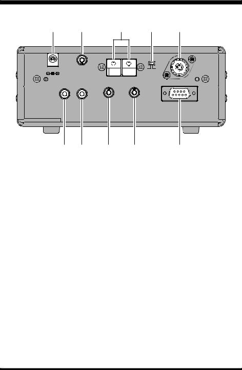
Rear Panel Connections
‡@ ‡A ‡B ‡C ‡D
DC 13.5V |
B |
A |
MUTE |
|
|
|
ANT |
|
|
|
ANT B
ANT A
EXT SP REC |
+8V |
IF OUT |
CAT
‡E ‡F ‡G ‡H |
‡I |
DC 13.5V Jack
This is the DC power supply connection for the VR-5000. Connect the Supplied PA28 AC adapter to this jack.
MUTE Jack
If using the VR-5000 with a transceiver, shorting this jack during transmit will mute receiver output and attenuate the RF signal input. Check the information provided with your particular transceiver for details regarding proper connection.
ANT B Terminal
Use these spring-loaded terminal connectors to connect a high-impedance antenna.
ANT Switch
This switch selects antennas connected to the ANT A jack or ANT B terminal.
ANT A Jack
Connect the 50 Ω coaxial feed line from your low-impedance antenna here, using a type-M (PL-259) connector.
6 |
VR-5000 OPERATING MANUAL |

Rear Panel Connections
EXT SP Jack
This 2-contact mini phone jack provides receiver audio for an external loudspeaker with an impedance of 4 ~ 16 Ω. Inserting a plug in this jack disables the loudspeaker.
REC Jack
This jack provides a constant level (8 mV @ 1 kΩ) audio output, which is unaffected by the VOL and TONE controls. This audio can be used for tape-recording purposes, and for connection to data demodulator/decoder equipment.
+8V Jack
This output jack provides 8V DC at up to 100 mA for providing DC voltage to low power accessories. The center contact is positive.
IF OUT Jack
This output jack provides low-level 10.7 MHz IF output.
CAT Jack
This 9-pin serial DB-9 jack allows external computer control of the VR-5000. Connect a serial cable here and to the RS-232C “COM” port on your personal computer.
VR-5000 OPERATING MANUAL |
7 |

Installation
PHYSICAL LOCATION OF THE RECEIVER
The VR-5000 should be located in a place that allows unobstructed ventilation around the cabinet. Although the VR-5000 does not produce significant amounts of heat, as with any electronic device a well-ventilated location will ensure that heat does not build up inside the cabinet.
Do not place the VR-5000 on top of another heat-generating device, and keep its top cover free of books, papers, and other objects which might impede ventilation.
If you utilize a computer in your monitoring location, we recommend that the VR-5000, its feedline, and its power cord all be kept as far away from the computer as possible, as the computer, its monitor, and/or other peripherals may radiate energy which can interfere with reception. Experimentation with several different locations may be necessary, in order to find the most interference-free location.
POWER CONNECTIONS
Base Station Operation
PA-28 AC Power Adapter Installation
Your VR-5000 is supplied with an AC Power Adapter, model PA-28, which provides the 13.5 Volts (DC) required by the VR-5000. We do not recommend any other type of power adapter for use with this product.
To install the PA-28, first connect the small, round DC output connector on the cable of the PA-28 to the DC 13.5V jack on the rear panel of the VR-5000. Then plug the PA-28 into the AC wall outlet.
When disconnecting the PA-28, it is recommended that you first turn the VR-5000 off, then unplug the PA-28 from the wall outlet, then unplug the round DC output connector.
When making power connections, always grasp the DC output connector, or the body of the PA-28, so as to minimize strain on the power cable. Never disconnect the PA-28 by pulling on either end of the cable, as this may lead to early mechanical failure of the PA-28.
DC Power Supply Connections
A well-regulated 13.5 Volt DC Power Supply may also be used with the VR-5000, providing it is capable of supplying 1 Ampere of current continuously. A DC cable is supplied with your VR-5000 for connection to a power supply.
When making power connections to a power supply, be absolutely certain to observe the correct polarity, as serious damage can occur if the connections are reversed.
Connect the wire containing the White Stripe to the Positive (+) DC output terminal, and connect the All-Black wire to the Negative (–) DC output terminal. Double-check your hookup before plugging the DC output connector into the VR-5000.
8 |
VR-5000 OPERATING MANUAL |
Installation
We recommend that, when using an external DC power supply, you turn the power supply on, then turn on the VR-5000; when shutting down, turn the VR-5000 off first, then turn off the power supply.
If the input voltage becomes too low (due to power supply failure or a problem in the DC cable), the VR-5000’s display will indicate “ERROR LOW VOLTAGE” If this should happen, check the output voltage from your power supply; if it is OK, then look for a problem in the DC cable.
Important Notice
Be absolutely certain to observe correct power supply polarity. Our Limited Warranty does not cover damage caused by improper power supply voltage or polarity.
ANTENNA CONSIDERATIONS
Antenna performance is critical to successful reception using the VR-5000. Extra time and care in installing your antenna(s) will reap great benefits for your monitoring station.
Best performance will always be obtained by the use of an outdoor antenna system, installed as high and in the clear as reasonably possible. Indoor antenna installations generally suffer from high levels of interference from computers and other electronic devices, as well as noise generated by fluorescent lights and home appliances.
Because of the wide frequency range of the VR-5000, no single antenna can be expected to provide optimized performance on all available frequencies. Therefore, separate discussions will address antenna principles for three general categories of antenna frequency range.
Important Safety Note
Never install an antenna where it (or its supporting mast) could possibly come in contact with utility power lines, even in a catastrophic wind storm. Such power lines carry thousands of volts of energy, and you can be killed instantly if the antenna connected to this product should come in contact with power lines, even for an instant.
The utilization of the services of a professional antenna-installation company is highly recommended, if you have any doubts about your ability to install your antenna system safely.
VR-5000 OPERATING MANUAL |
9 |

Installation
Antennas for Lowand Medium-Frequency Reception (below 2 MHz)
Good all-around reception will be obtained using a single long random length wire, connected to the (red) Hi-Z terminal on the rear panel. The wire should be supported as high above ground as possible by insulators at the end at possibly mid-span, depending on the length of the wire. The longer the wire, the stronger will be the signals received.
Insulated wire is generally preferred, as it is less susceptible to corrosion. The wire should be clear of nearby metallic objects to the greatest extent possible.
A good earth ground connection, as shown in the illustration, can be essential to good performance of a random length antenna. It may be connected to the Black terminal just to the left of the Red antenna terminal.
Antennas for Short-wave (HF)
Optimum performance on frequencies between 2 and 30 MHz will generally be obtained through use of a resonant antenna with an impedance near 50 Ohms at the frequency of interest. Broadband or multiband “Dipole” antennas, such as the Yaesu model YA-30, are available from your dealer.
If a particular frequency in the HF range is of interest to you, a half-wavelength Dipole antenna may easily be constructed from readily-available materials. A dipole consists of a length of wire, cut according to the formulas below; the wire is broken in the middle, and insulators are installed at each end and in the middle. A 50or 75-Ohm coaxial cable is then connected in the middle, with the center conductor of the coaxial cable going to one side of the center insulator and the shield of the coaxial cable connecting to the other side of the insulator.
Length (meters) = 142.5 ÷ Frequency (MHz), or
Length (feet) = 468 ÷ Frequency (MHz)
Better “balance” in the antenna’s reception pattern will be obtained if you make a coil of coaxial cable, ten turns of about 10” (25 cm) in diameter, just below the center insulator of the Dipole antenna. Tape the turns together securely to hold them in place.
The Dipole will work well near its design frequency. However, if you are interested in reception on several frequency bands separated by a number of MHz (for example, the 7 MHz band and the 15 MHz band), you may wish to cut wires for each band of interest, and solder the center ends of these different-length wires together on each side of the center insulator. The outer ends may then be fanned out so that they are separated by a few feet.
Install a type “M” (“PL-259”) coaxial connector at the station-end of the coaxial cable, and connect the coaxial cable to the coaxial jack (“Antenna A”) on the rear panel of the VR-
5000.
10 |
VR-5000 OPERATING MANUAL |

Installation
Antennas for VHF and UHF Reception
Any antenna used for reception above 30 MHz will be fed with coaxial cable, so it must be connected to the Antenna A jack.
The wide frequency coverage of the VR-5000 means that a wide-band vertical antenna (such as the “Discone” type) will be required for reasonable performance on the VHF and UHF bands. Optimized narrow-band vertical antennas will provide better performance on a specific frequency range, at the expense of poorer performance on other frequencies.
While vertical orientation of the antenna will be compatible with the configuration of the majority of base and mobile stations being heard, horizontally-oriented antennas are often used by amateur radio stations using the USB and CW modes in the 50 MHz, 70 MHz (U.K.), 144 MHz, and 432 MHz bands.
Whichever antenna(s) you use, it is important to use the best quality (lowest loss) coaxial cable possible, as cable loss in a long length of coaxial cable can be very high if smalldiameter cable is used. This will reduce the strength of the incoming signals, making reception of weaker signals difficult or impossible.
Your local dealer will be in the best position to recommend an antenna type, as well as installation tips, for successful monitoring in your area.
Antenna Switching
Antenna switching between the coaxial Antenna-A and long-wire Antenna-B jacks (on the rear panel of the receiver) is accomplished using the ANT A/B slide switch, located between the two antenna jacks on the rear panel of the VR-5000. An antenna may be connected to each jack; there is no need to remove an antenna when the alternate jack is being used.
If multiple antennas are to be used in conjunction with the coaxial Antenna A jack, consult your dealer regarding the procurement of a coaxial antenna switch suitable for the frequency range of interest.
Important Note Regarding Antenna Safety!
Disconnect all antennas connected to the VR-5000 if you receive information that a lightning storm is approaching your area. Extremely high voltages can be fed into your station through an antenna system, and a receiver struck by lightning will be permanently damaged or destroyed.
Do not, however, attempt to disconnect your antenna(s) if a lightning storm is in progress in your immediate area. You could be killed instantly if you are handling the antenna or its feedline at the moment lightning strikes!
VR-5000 OPERATING MANUAL |
11 |
Installation
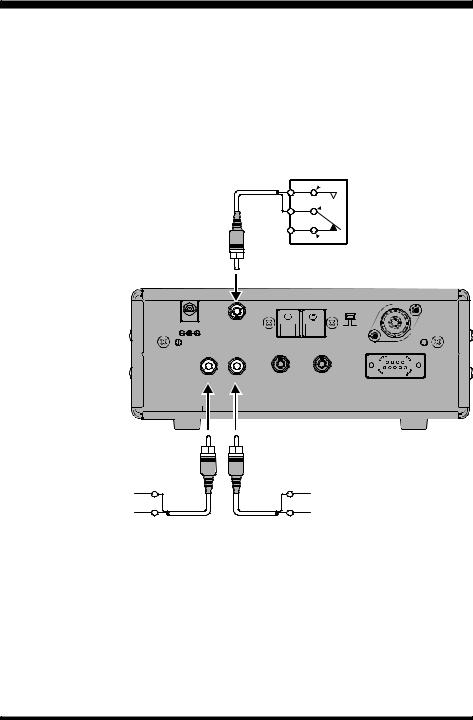
MUTE Terminal Connections
The MUTE jack on the rear panel allows the receiver to be silenced during transmission, should the VR-5000 be utilized with an external transmitter (not available from Yaesu). Typically, such a transmitter will have an internal relay, the contacts of which will close to ground during transmission; connection of a cable connected to this type of switching system will cause the audio output from the VR-5000 to be cut off (when the center conductor is shorted to ground).
If an external transmitter is used, it is important also to disconnect all antennas connected to the VR-5000 during transmission. An external switch or relay will be required for this task.
Transmmiter triggerd relay
Normally Open (N.O)
MUTE
 Common
GND
Normally Closed (N.C)
DC 13.5V |
|
B A |
|
|
|
MUTE |
|
ANT |
|
|
|
|
|
ANT B |
|
|
ANT A |
EXT SP REC |
+8V |
IF OUT |
|
|
CAT |
GND |
GND |
EXT SP (4 Ω 16 Ω) |
8 mV (rms) at 1 kΩ impedance |
REC Jack Connections
The rear panel’s REC jack provides constant-level “Line Out” audio output, suitable for connection to a tape recorder, modem, or computer sound card for recording or datadecoding purposes. The front panel Volume control does not affect the output level at this jack, which is 8 mV (rms) at 1 kΩ impedance.
EXT SP Jack Connections
An external loudspeaker may be connected to the rear panel’s EXT SP jack. The external loudspeaker should have an impedance between 4Ω and 16Ω. Do not connect earphones to this jack, as the output level is high enough to yield the potential for hearing damage.
12 |
VR-5000 OPERATING MANUAL |

Installation
+8V Jack Connections
The +8V jack may be used for powering of small accessories. The output current, however, is limited to 100 mA or less, so check the current requirements for your accessory before connecting it to this jack.
Exercise particular care with any cables connected to this jack. If the far end of the cable should become shorted to ground (perhaps by accidental contact with a metal surface), the internal fuse for this jack will “blow” instantly.
IF OUT Jack Connections
A portion of the 10.7 MHz Intermediate Frequency (IF) stage signal is available via this jack. This may be used for observing signal characteristics, or a separate receiver may be connected here to monitor FM broadcast sub-carrier signals, etc.
VR-5000 OPERATING MANUAL |
13 |

Basic Operation
INTRODUCTION
The VR-5000 utilizes a “VFO” (Variable Frequency Oscillator) tuning system for frequency selection. Two VFOs are provided, termed the “MAIN” and “SUB” VFOs in this manual. The VFOs utilize tuning “steps” which vary between operating modes, and which may be set by the owner according to your location and operating preferences. Fundamentally, however, a VFO may simply be thought of as a tuning dial for the receiver.
Details regarding setup and operation of the VR-5000 are found in the pages to follow.
TURNING THE POWER ON/OFF
Press and hold the orange PWR switch for one second to turn the radio on and off. The one-second delay minimizes the chance that the radio will accidentally be turned on or off by bumping the PWR switch.
ADJUSTING THE VOLUME AND SQUELCH
1.Rotate the MAIN VOL knob to adjust the audio volume of the MAIN VFO. Rotate the SUB VOL knob to adjust the audio volume of the SUB VFO. Clockwise rotation of these VOL knobs increases the volume level. Both VOL knobs can be rotated to adjust the relative balance of receiver audio between the two VFOs during dual reception.
2.The VR-5000 squelch system allows you to mute the receiver’s audio output when no signals are being received. To set the squelch, turn the SQL knob fully counterclockwise, then turn it clockwise just past the point where the background noise is silenced. Do not rotate the SQL knob much beyond this threshold point; if you do, the receiver will not respond to weak signals.
3.Rotate the TONE knob to adjust the receiver’s audio characteristics. Clockwise rotation of the TONE knob emphasizes the high-frequency component. The TONE knob affects both the MAIN and SUB VFO audio.
FREQUENCY NAVIGATION
Tuning DIAL
Rotating the DIAL knob allows tuning in the pre-programmed steps established for the current receiving band. Clockwise rotation of the DIAL knob causes the VR-5000 to be tuned toward a higher frequency, while counter-clockwise rotation will lower the receiving frequency.
If you press the [F] key momentarily, then rotate the DIAL knob, frequency steps of 1 MHz will be selected. This feature is extremely useful for making rapid frequency excursions over the wide tuning range of the VR-5000.
14 |
VR-5000 OPERATING MANUAL |

Basic Operation
UP( )/DOWN( ) Tuning
Pressing the [ ( )/ ( )] keys allows tuning in the pre-programmed steps established for the current receiving band. Pressing the [ ( )] key causes the VR-5000 to be tuned toward a higher frequency, while pressing the [ ( )] key will lower the receiving frequency.
If you press the [F] key momentarily, then press the [ ( )/ ( )] keys, frequency steps of 10 MHz will be selected. The larger 10 MHz hops are extremely useful for making rapid frequency excursions over the wide tuning range of the VR-5000.
Direct Keypad Frequency Entry
The desired receiving frequency may be entered directly from the keypad.
The receiving mode (FM, SSB, AM, etc.) will automatically be set once the new frequency is entered via the keypad, based on the operating frequency you have chosen.
To enter a frequency from the keypad:
1.Enter the “MHz” portion of the frequency on which you wish to receive.
2.Enter the decimal point after the “MHz” portion by pressing the [• (BEEP)] key.
3.Enter five more digits to complete the frequency.
4.If there are “zeros” at the end of the frequency, you may press the [ENT(SET)] key after the final non-zero digit.
Examples:
To enter 146.16250 MHz, press [1] [4] [6] [•] [1] [6] [2] [5] [0]
To enter 950 kHz, |
press [•] [9] [5] [0] [0] [0] |
To enter 445.40000 MHz, press [4] [4] [5] [•] [4] [ENT]
MODE SELECTION
The VR-5000 automatically selects a default receiving mode according to the frequency band on which you are receiving. However, many bands (especially HF Short-wave) may use a variety of transmission modes in a particular frequency segment.
If you want a change the receiving mode, press the [MODE(ADRS)] key. The receiving modes available are:
 AUTO
AUTO  LSB
LSB  USB
USB  CW
CW 
 WFM
WFM  FM-N
FM-N  WAM
WAM  AM
AM  AM-N
AM-N 
VR-5000 OPERATING MANUAL |
15 |
Basic Operation
CHANNEL STEP SELECTION
Operation of the VR-5000 initially is set up in the “AUTO” mode (mentioned in the previous section), whereby the reception mode (such as AM or FM) is automatically set according to the frequency in use; at the same time, the channel steps typically used in that frequency segment are also programmed automatically.
However, some frequency segments involve several different services which may use different channel steps. So you may wish to modify the channel steps; to do this, you must first exit the “AUTO” mode, then select the desired steps. The procedure is:
1.Note the operating mode in which you are operating via the “AUTO” mode (for example, FM-N).
2.Press the [MODE(ADRS)] key as many times as required to shift to the operating mode which had been selected by the “AUTO” mode.
3.Press the [STEP(PLAY)] key as many times as required to shift to the desired channel step selection (for example, 5 kHz).
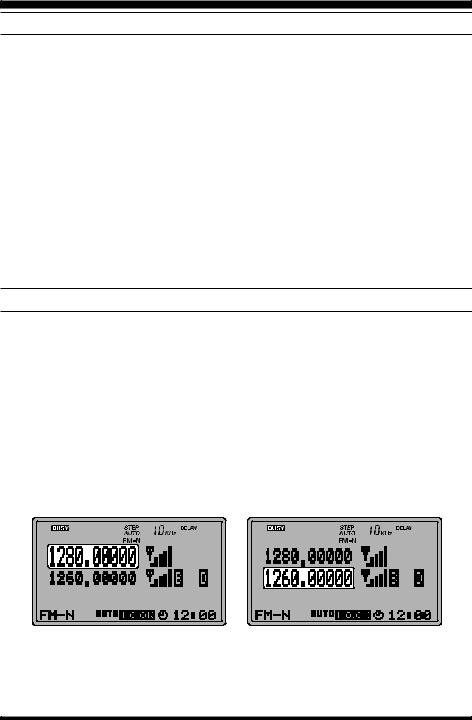
DUAL RECEIVE
The VR-5000 provides two VFOs (MAIN VFO and SUB VFO), which operate in a Dual Receive configuration (simultaneous reception using both VFOs). The SUB VFO frequency must be set within ±20 MHz of the MAIN VFO frequency (for example, if the MAIN VFO is set to 1280.000 MHz, the SUB VFO can be set to 1260.000 ~ 1300.000 MHz). Also, the SUB VFO may be set only AM or FM-N modes.
The MAIN VFO is the upper displayed frequency, while the SUB VFO is the lower displayed frequency. The relative size of the frequency displays indicates which VFO you currently are tuning on (the larger display size indicates the “active” VFO). Independent Volume controls are provided for each VFO; just turn the Volume down if you do not wish to listen to communications on a particular channel.
MAIN VFO |
SUB VFO |
16 |
VR-5000 OPERATING MANUAL |

Basic Operation
Here are some of the features available during Dual Receive operation:
Press the [M/S(SUB SET)] key momentarily to toggle the operating VFO between the MAIN VFO and SUB VFO.
When tuning on the MAIN VFO, the SUB VFO frequency will track the MAIN VFO (VFO Tracking feature).
To disable the VFO Tracking feature, press the [M/S(SUB SET)] key after the [F] key is pressed. Repeat the same procedure to re-enable the VFO Tracking feature again.
To disable the SUB VFO, and erase its contents, press the [CLR(PRI CLR)] key after the [F] key is pressed. Pressing the [M/S(SUB SET)] key will re-activate the SUB VFO. When the SUB VFO re-appears, it will have been reset to the MAIN VFO’s frequency.
Press the [COPY(REC)] key to copy the SUB VFO’s frequency data to the MAIN VFO.
SETTING THE CLOCK
1.Press the [F] key momentarily, then press the [ENT] key.
2.Rotate the DIAL knob to set the cursor to the “MISC” menu, then press the [ENT] key.
3.Rotate the DIAL knob to set the cursor to the “CLOCK” menu option, then press the [ENT] key.
4.Enter the present time via the keypad.
Example 1: Set to 9:38, Press [0] [9] [3] [8]. Example 2: Set to 13:20, Press [1] [3] [2] [0].
5.Rotate the DIAL knob to set the cursor to the “END” menu option, then press the [ENT(SET)] key.
6.Confirm that the cursor is on the “WRITE” menu option, then press the [ENT] key.
7.Press the [F] key momentarily, then press the press the [4(SPL)] key.
8.Rotate the DIAL knob to set the cursor to the “UTC set” menu option, then press the [ENT(SET)] key. The World Clock and its accompanying World Atlas will appear.
9.Rotate the DIAL knob to select the desired area.
10.Press the [F] key momentarily, then press the press the [9(TIMER)] key.
11.Press the [CLR(PRI CLR)] key then press the [ENT(SET)] key.
12.Setup of the clock is now complete.
VR-5000 OPERATING MANUAL |
17 |

Basic Operation
RECEIVING SHORT-WAVE BROADCAST STATIONS
A special bank of prominent Short-wave Broadcast stations has been pre-programmed at the factory, for quick tuning. Each station selection will have been programmed with four of its most-often used frequencies, representing both night-time frequencies (generally below 10 MHz) and day-time frequencies (generally above 10 MHz).
Of course, you are not “required” to listen just to these stations; many other stations will be found in the frequencies adjacent to those stored in the special Short-wave Broadcast Memory Bank. However, the pre-programmed stations will provide a “quick start” to your Short-wave listening enjoyment!
To utilize the pre-programmed Short-wave Broadcast Memory Bank:
1.Press the [F] key momentarily, then press the [6(S.CALL)] key to recall the special Short-Wave Broadcast Station Memory Bank.
2.Press the [ ( )/ ( )] keys to select the desired Broadcast Station.
3.Rotate the DIAL knob to select the Broadcast Station’s frequency from among the preprogrammed choices. At different times of the day, different frequencies will be optimum for each station.
4.To exit from the special Short-wave Broadcast Station Memory Bank, press the [CLR(PRI CLR)] key.
18 |
VR-5000 OPERATING MANUAL |
 Loading...