


G-800SA
G-800SA
G-1000SA
Antenna Rotator & Controller
User Manual
VERTEX STANDARD CO., LTD.
4-8-8 Nakameguro, Meguro-Ku, Tokyo 153-8644, Japan
VERTEX STANDARD
US Headquarters
10900 Walker Street, Cypress, CA 90630, U.S.A.
YAESU EUROPE B.V.
P.O. Box 75525, 1118 ZN Schiphol, The Netherlands
YAESU UK LTD.
Unit 12, Sun Valley Business Park, Winnall Close
Winchester, Hampshire, SO23 0LB, U.K.
VERTEX STANDARD HK LTD.
Unit 5, 20/F., Seaview Centre, 139-141 Hoi Bun Road,
Kwun Tong, Kowloon, Hong Kong

IMPORTANT !
The installation of a rotatable antenna on a tower system is a dangerous and potentially life-threatening task, if due care
is not taken.
A tower must never be installed in a position where it could fall across power distribution cables in the event of a
catastrophic tower failure during a windstorm or earthquake.
The control cable attached to this rotator could, in the event of a nearby or direct lightning strike, carry lethal voltages
down the cable and into your home. Yaesu strongly recommends the installation of suitable lightning arrestors on all
control cables and coaxial lead-in cables from your antenna installation. See your dealer for details of available lightning-protection devices.
If an electrical storm should be reported in your area, quickly unplug the control cable from the rear of the rotator’s
controller box, and disconnect the AC cable from the wall outlet. Disconnect the coaxial cable(s) from the antenna(s) as
well. Do this only if the lightning is not in your immediate area, as you could be killed instantly if lightning should
strike while you are holding a cable.
If you have any doubts about your ability to install this rotator safely, enlist the services of a professional antenna
installation company.
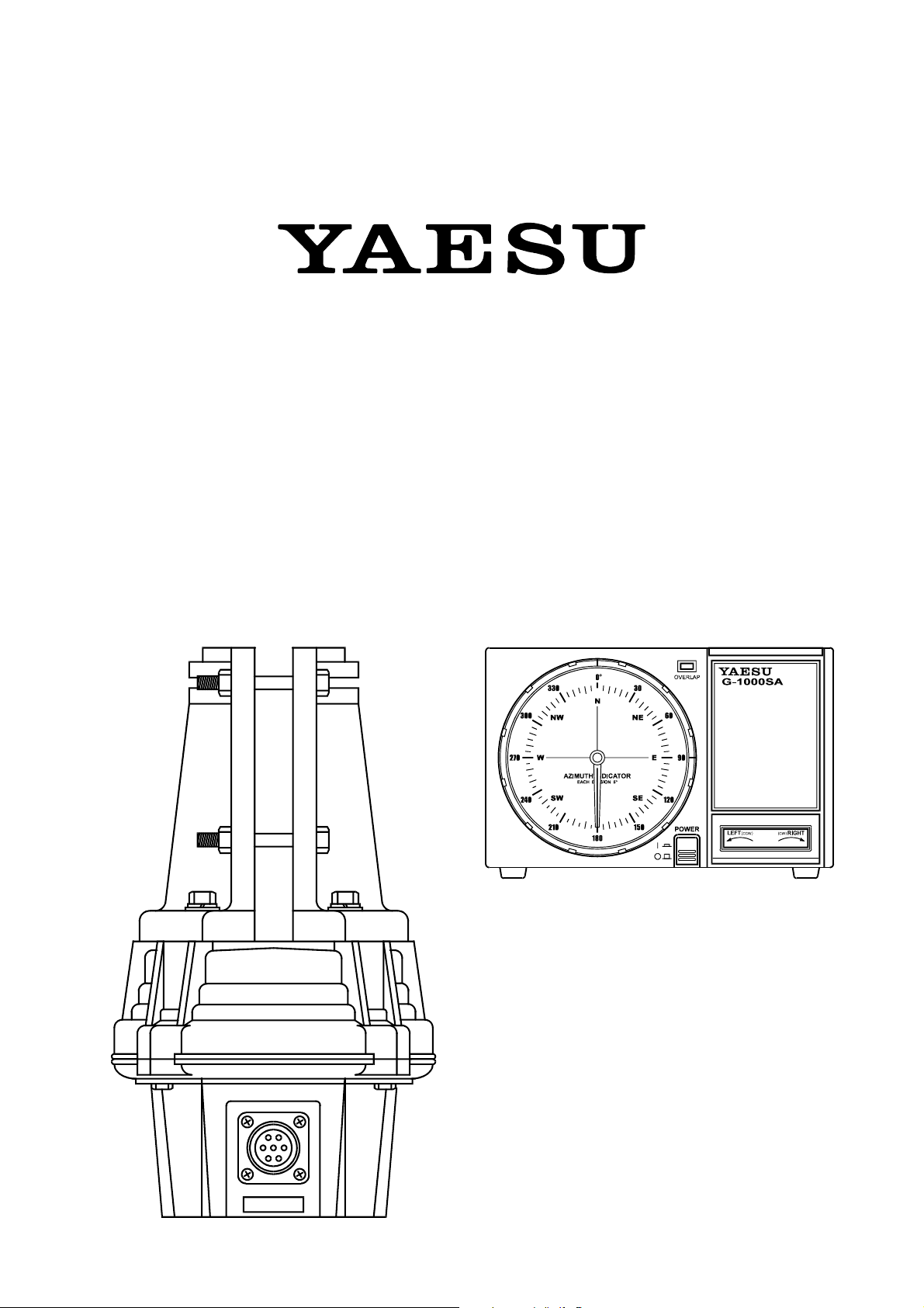
G-800SA
G-1000SA
Heavy-Duty Antenna Rotator & Controller
The Yaesu G-800SA and G-1000SA are designed to
rotate large tower-mounted amateur and professional antenna arrays under remote control from the station operating position. The clamshell rotator design utilizes 98
7/16-inch dual-stacked circumferential ball bearings to
distribute load over the full diameter of the housing. This
design minimizes stress and wear, and practically eliminates the possibility of destructive water entry: there is
no shaft hole in the top of the housing.
Instead of the usual AC motor drive used in older rotator
designs, the G-800SA and G-1000SA use a DC motor,
obviating the need for a large starting capacitor with its
potential for failure exposed to outside temperature variations. The factory-lubricated rotator unit is housed in
melamine resin-coated die-cast aluminum, intended to
provide maintenance-free operation under all climatic
conditions. A mast alignment gauge on the rotator housing simplifies accurate mechanical alignment during installation.
The handsome desktop controller matches the design of
modern transceivers, providing 360° radial indication of
actual antenna bearing azimuth.
The operator may select the stopper heading (the bearing through which the rotator cannot be turned) most
convenient for his location and operation, allowing full
rotation through north, south or both, if desired. In any
case, 90° overlapping rotation allows rotation through
the selected stopper heading (450° total rotation).
The rotator is intended for mounting inside a support
tower (not supplied), at least 1 meter from the top, with
an optional (Yaesu model GS-065 or GS-680U) thrust
bearing above.
The G-800SA and G-1000SA includes one mast clamp
and related hardware, plus plug connectors for both the
rotator and controller. A six conductor cable of the necessary length must be supplied by the owner.
Please read this manual through carefully before installing the rotator, to acquaint yourself with the procedures
that will be required, and to ensure that you have all necessary items for your installation.
G-800SA/G-1000SA User Manual Page 1
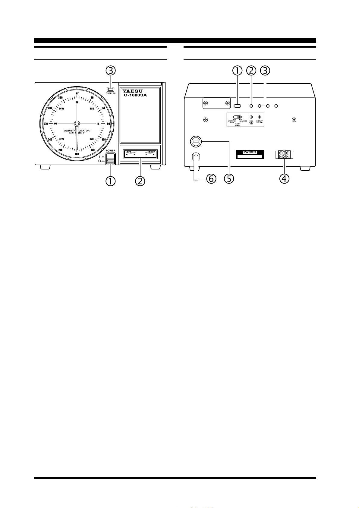
Controller Switches & Controls
FRONT PANEL REAR PANEL
POWER Switch
Press this switch to turn the controller on to rotate
the antenna. Turn it off when the rotator is not in
use.
LEFT/RIGHT Seesaw Switch
Press the LEFT side of this switch to rotate the antenna counter-clockwise (CCW). Press the RIGHT
side to rotate the antenna clockwise (CW).
OVERLAP Indicator
This red LED glows when the antenna is rotated
beyond about 180° (to 270°) from its original installation direction (180°). Check this indicator before rotating the antenna clockwise, and turn the
antenna counter-clockwise to the desired position if
the indicator is on.
SELECT SWITCH
Set this switch to the “ADJ. MODE” position while
calibrating the internal adjustments of the controller. During normal operation, however, set this switch
to the “OPERATION MODE” position.
FULL SCALE ADJ Potentiometer
This control calibrates the maximum rotation angle
(range) of the azimuth indicating needle to match
the maximum angle of the rotator.
OVERLAP LED ADJ Potentiometer
This control calibrates the OVERLAP Indicator to
match the azimuth indicating needle.
Rotator Control Cable Jack
The supplied control cable from the rotator connects
to this 6-pin jack.
FUSE Holder
This holder requires a 2-A fuse for 117V AC. If the
fuse is blown, replace only with a fuse of the same
rating.
AC Cable
Connect this cable to the 117V AC wall outlet.
G-800SA/G-1000SA User ManualPage 2
Antenna Considerations
The types of antennas that can be attached to this product differ widely, depending on the installation method, local
terrain, and the maximum expected wind speeds at your location.
The following pages described typical antennas which are acceptable for installation with the G-800SA or G-1000SA.
The discussion below assumes maximum wind speeds of 30 meters per second, and it is recommended that you include
a safety margin of at least 40% to account for higher wind gusts or other factors which might potentially cause
damage to your installation.
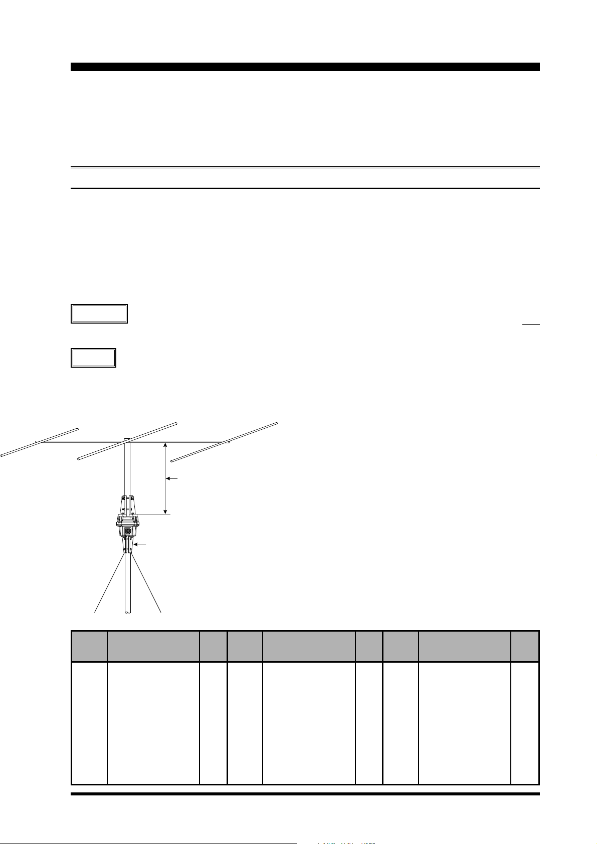
POLE-MOUNTED ANTENNAS
Mounting of the rotator on a pole or mast results in a significant de-rating of the size of the antenna which can be
mounted, due to the tremendous bending forces applied to the rotator’s clamps. For pole mounting, the product of
multiplying the [Antenna Wind Load Area (in m2)] by the [Height of the Antenna Mast (in m)] must be less than 0.45.
See below Table and Figure.
[
Antenna Wind Load Area
] x [
Height of Antenna Mast] = 0.45
Refer to the antenna manufacturer’s specification sheet for determining the weight and the surface area of the proposed
antenna.
Example
For a 14 MHz 3-element Yagi of Surface area of 0.7 m2 (see Table 1), the above specifications for pole
mounting will be met if the antenna is mounted on a mast not longer than 0.3 m (0.7 m2 x 0.3 m = 0.21
< 0.27 [0.45 x 40% safety margin].
Advice
We recommend that your antennas/mast should not exceed 60% of the maximum rating, to ensure a
safety margin.
Less than 0.3m
Optional Mast Clamp GC-038
Example of a 14 MHz Band, 3-Element Yagi Antenna
Wind Loading Areas for Common Antennas (Typical)
Band
(MHz)
7
7
7
7
14
14
14
21
21
21
21
21
Elements
2-element
1-element, w/loading coi ls
2-element, w/loading coi ls
3-element, w/loading coi ls
3-element
4-element
5-element
3-element
4-element
5-element
6-element
2-element, Swiss Quad
Area
(m
2.2
0.2
0.6
1.1
0.7
1.2
1.7
0.45
0.6
0.8
1.3
0.3
2
)
Band
(MHz)
28
28
28
28
7/14
7/14
14/21
14/21
21/28
21/28
14/21/28
14/21/28
Elements
3-element
4-element
5-element
2-element, Swiss Quad
3-element, trapped
4-element, trapped
3-element, trapped
4-element, trapped
3-element, trapped
4-element, trapped
3-element, trapped
4-element, trapped
Area
(m
0.3
0.42
0.6
0.3
0.5
0.8
0.4
0.5
0.3
0.4
0.4
0.5
2
)
Band
(MHz)
50
50
50
50
14 4
14 4
14 4
14 4
43 0
43 0
43 0
43 0
Elements
4-element
5-element
6-element
2-element, Swiss Quad
10 - ele me nt
10-elem en t, s tacked
10-element, x 4
10-element, x 4 x 2
12 - ele me nt
12-elem en t, s tacked
12-element, x 4
12-element, x 4 x 2
Area
(m
0.25
0.3
0.37
0.3
0.2
0.44
0.95
2.0
0.06
0.12
0.3
0.6
2
)
G-800SA/G-1000SA User Manual Page 3
 Loading...