

Page 1
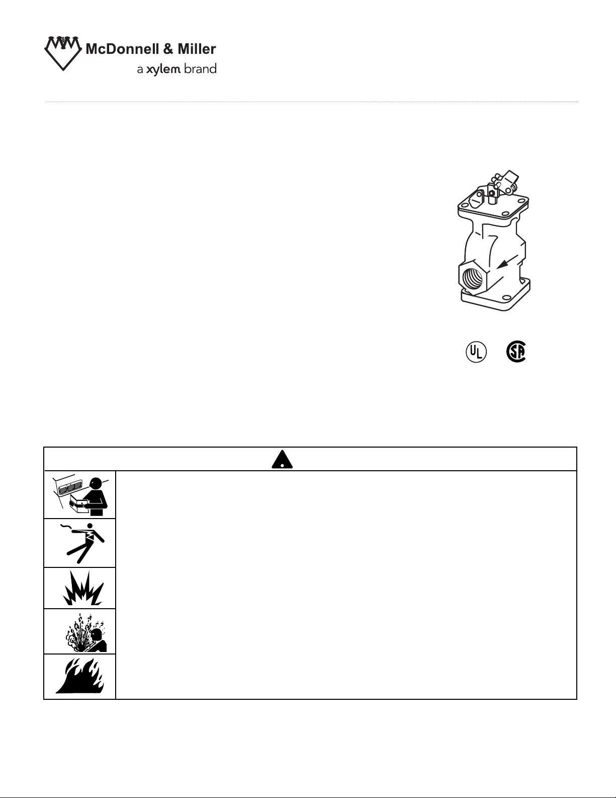
Valve, Cartridge and Strainer
!
Replacement Kit
Assembly Kit SA-47-101-102 for
Series 47, 247 and 847
Mechanical Water Feeders
Assembly Kit SA51-101-102 for
INSTRUCTION MANUAL
MM-305G
Series 51 and 851 Make-Up
Water Feeders
CAUTION
WARNING
• Before using this product read and understand instructions.
• Save these instructions for future reference.
• All work must be performed by qualified personnel trained in the proper application, installation, and maintenance of plumbing, steam, and electrical equipment and/or systems in
accordance with all applicable codes and ordinances.
• To prevent electrical shock, turn off the electrical power before working on the control.
• Relieve pressure and drain the water to a level below the control. Let boiler cool down to
80˚F (27˚C).
®
WARNING
Failure to follow this warning could cause property damage, personal injury or death.
Page 2
!
INSTALLATION
TOOLS NEEDED:
One (1) long nose pliers, one (1) flathead screwdriver, and one (1) Allen wrench.
STEP 1 - Preparation
WARNING
• To prevent electrical shock, turn off the electrical power before working on the control.
• Relieve the pressure and drain the boiler so that the water level is below the control. Allow the boiler to
cool to 80˚F (27˚C).
Failure to follow this warning could cause property damage, personal injury or death.
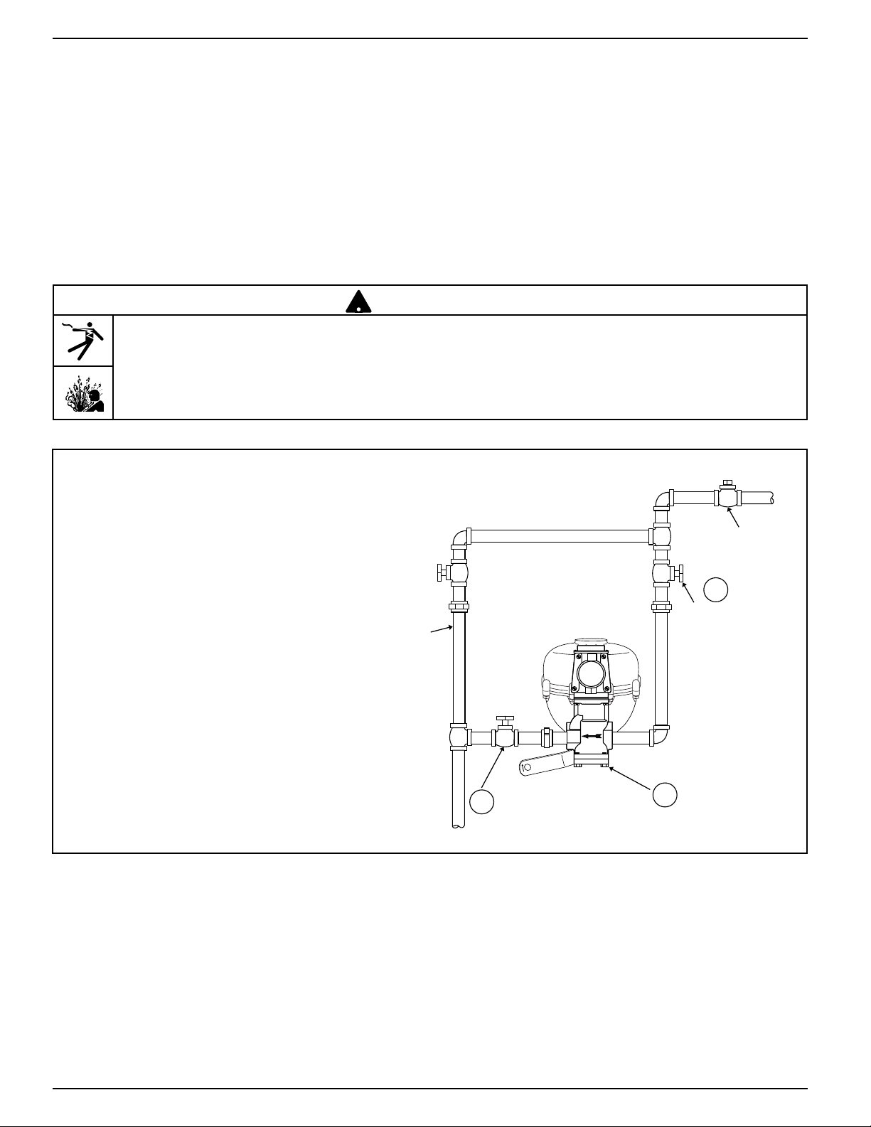
a. Close the water supply valve (A) and (B).
Remove the inlet and outlet piping from the
water feeder valve (C).
BY-PASS
B
OUT
VALVE
CITY WATER
SUPPLY
A
WATER
SUPPLY VALVE
IN
C
2
Page 3

STEP 2 - Remove the Original Valve, Cartridge and Strainer
a. Using long nose pliers, remove cotter pin (D)
and pivot pin (E) and discard. Remove four (4)
screws (F).
NOTE: Newer models have Allen screws.
D
E
F
STEP 3 - Install the New Valve, Cartridge and Strainer
1a. For one-piece and two-piece float arms: with the
valve linkage ears (H) straddling the float
arm (G), install the valve. Reinstall the four (4)
screws (F). Tighten to approximately 10 lb•ft
(13.6 N•m) of torque.
b. Align the float arm holes (G) with the valve
linkage and insert the pivot pin. Insert new cotter
pin (D) into new pivot pin (E) and bend the cotter
pin.
G
H
D
E
F
3
Page 4

2. Reinstall the inlet and outlet piping to
the water feeder valve (C). NOTE:
Model 47-C inlet and outlet are
reversed. Open supply valve (A).
Open supply valve (B). Following the
installation instructions that came with
the water feeder, check for proper
operation. Make sure there are no
leaks.
BY-PASS VALVE
(EXAMINE VALVE TO MAKE SURE
IT IS CLOSED TIGHTLY)
BY-PASS
OUT
CITY WATER
SUPPLY
A
WATER
SUPPLY VALVE
IN
INSTALLATION COMPLETE
MAINTENANCE
SCHEDULE:
• Disassemble and inspect the strainer annually.
Thoroughly clean the strainer screen or replace.
• Remove and inspect cartridge annually.
Thoroughly clean by rinsing with clear water
or replace.
VALVE
B
CONNECT TO RETURN HEADER
ON BOILER SIDE OF ALL VALVES
C
Xylem Inc.
8200 N. Austin Avenue
Morton Grove, Illinois 60053
Phone: (847) 966-3700
Fax: (847) 965-8379
www.xyleminc.com/brands/mcdonnellmiller
McDonnell & Miller is a trademark of Xylem Inc. or one of its subsidiaries.
© 2012 Xylem Inc. MM-305G April 2012 Part No. 246739
 Loading...