

Page 1

Series 1575
Low Water Cut-Off/Pump Controller
For Steam Boilers and Other Level Control Applications
FEATURES
Probe Chamber:
• Cast Iron Body
• Sight Glass Tappings
• Gage Cock Tappings
• Stainless Steel Probes
• NEMA 4X Electrical Enclosure
• 250 psi Maximum Working Pressure
INSTRUCTION MANUAL
MM-286B
Probe Chamber
MODEL 150E
LWCO & Pump
CONTROLLER
Electronic Control Unit
WARNING
• Before using this product read and understand instructions.
• Save these instructions for future reference.
• All work must be performed by qualified personnel trained in the proper application, installation, and maintenance of plumbing, steam, and electrical equipment and/or systems in
accordance with all applicable codes and ordinances.
• To prevent serious bu r n s , the boiler must be cooled to 80˚F (27˚C) and the pressure must be
0 psi (0 bar)
• To prevent electrical shock , turn off the electrical power before making electrical connections.
• This low water cut-off must be installed in series with all other limit and operating controls
installed on the boiler. After installation, check for proper operation of all of the limit and
operating controls, before leaving the site.
• We recommend that secondary (redundant) low water cut-off controls be installed on all
steam boilers with heat input greater than 400,000 BTU/hour or operating above 15 psi of
steam pressure. At least two controls should be connected in series with the burner control
circuit to provide safety redundancy protection should the boiler experience a low-water
condition. Moreover, at each annual outage, the low water cut-offs should be dismantled,
inspected, cleaned, and checked for proper calibration and performance.
• To prevent serious personal injury from steam bl ow dow n , connect a drain pipe to the contro l
opening to avoid exposure to steam discharge.
• To prevent a fire, do not use this low water cut-off to switch currents over 16A, 1 Hp at
120 VAC or 8A, 1 Hp at 240 VAC, unless a starter or relay is used in conjunction with it.
before
servicing
Page 2
California Proposition 65 warning! This product contains chemicals known to the
•
state of California to cause cancer and birth defects or other reproductive harm.
Previous controls should never be installed on a new system. Always install new
•
controls on a new boiler or system.
Failure to follow this warning could cause property damage, personal inj ury or death.
CAUTION:
•
A more frequent replacement interval may be necessary based on the condition of
the unit at time of inspection. McDonnell Miller s warranty is one (1) year from date
of installation or two (2) years from the date of manufacture.
Electronic Control Unit
!
&
'
Burner Relay Time Delay
The field-adjustable time delay (DOB) helps to
p r e vent nuisance bu r ner shut-dow n . The number
of seconds water needs to be off the longest probe
b e f ore the bu r ner will shut down can be set
b e t w een 0 and 60 seconds.
Redundant Low Water Cut-Off
When the boiler water drops below the middle
p r o b e , a 3 minute timing circuit will be activa t e d . I f
water does not return to the middle probe within
three minu t e s, the bu rner relay will shut dow n . T h e
Red LED will flash once eve r y second if this
condition occurs.
• Automatic Reset units will automatically reset
when the water level is restored to the middle probe.
N O T E : The timing circuit will automatically reset
if the water level returns to the middle probe within
3 minu t e s.
Redundant Pump Off
The pump relay will be activated, turning the pump
on after water drops below the middle probe. If the
water level is not restored to the top probe within 3
m i nutes the pump relay will be deactivated, shutting
off the pump
. After the pump relay is deactiva t e d ,
n o r mal operation is resumed. Water must again
drop off the middle probe to activate the pump
r e l a y. There is no LED signal for this occura n c e.
A d j u s t a ble Pump Diffe r e n t i a l s
The water level positions for turning the pump on
and off and obtaining the needed pump diffe r e n t i a l s
are changed by cutting the length of the middle and
s h o r test probes.
2
Page 3
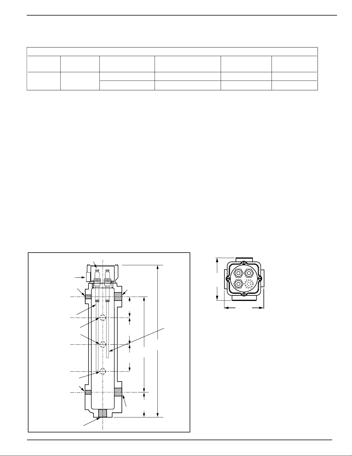
SPECIFICATIONS
4-3/16"
(106.4)
4-3/8"
(111)
A
B
C
D
2-1/2"
(63.5)
3-1/4"
(82.5)
3-1/4"
(82.5)
3-1/8"
(79.4)
1" NPT
11-1/2"
(292)
18-5/8"
(473)
1/2" NPT
1/2" NPT
1/2" NPT
CONDUIT
CONNECTION
1"
NPT
1" NPT
1/2" NPT
ELECTRODE
PRE-CUT
9" PROBE ROD
CUT AS
NEEDED
M a x i m um Pressure: 150 psi (10.5 kg/cm2)
ELECTRICAL RATINGS & SWITCH RATINGS
Supply Probe Full Load (Amps) Locked Rotor (Amps) Pilot Duty (VA) Motor (HP)
Voltage Voltage NO (NC), VAC NO (NC), VAC NO (NC), VAC NO (NC), VAC
120 VAC 5 VAC 16 (5.8), 120 96 (34.8), 120 470 (290), 120 1 (1/4), 120
50/60 HZ maximum 8 (2.9), 240 48 (17.4), 240 470 (290),240 1 (1/4), 240
Burner Delay (DOB): 0 to 60 seconds (Field Adjustabl e )
Ambient Te m p : 120˚F Max.
N O T E : The circuit board is protected with a sensor which will
shut down the unit if the temperature at the board ex c e e d s
176˚F (80˚C). The board will reset when the temperature at
the board drops below 167˚F (75˚C).
M a x i m um System Water Te m p e r a t u r e : 406˚F (208˚C)
M a x i m um System Water Pressure: 250 psi (17.6 kg/cm2)
M a x i m um System Steam Pressure: 250 psi (17.6 kg/cm
All probes in the Series 1575 units are sent from the factory pre-cut to
9" length (229mm). Any of the probes can be used as the low water
cut-off level probe. The 9" length positions the probe at the low water
cut-off cast-in line on the chamber body. The remaining probes can be
‘cut to length’ using a metal cutting saw to achieve desired pump control
(pump on/pump off) and pump differential levels. Approximately 1 inch
of the metal probe rod should be exposed below the PTFE
2
)
coating.
3
Page 4

SPECIFICATIONS (cont.)
SWITCH SETTINGS:
When the water level in the boiler drops below the
middle probe, the circuit is broken which will
a c t i v ate the pump relay, turning the pump on. W h e n
the water level rises above the shortest probe, the
circuit is made and the pump relay is deactiva t e d ,
t u r ning the pump off.
When the water level in the boiler drops below the
longest probe, the circuit is broken which will
d e a c t i v ate the bu rner relay, turning the bu rner off.
When the water level is restored to the middle
p r o b e , the bu r ner relay will be activated (bu rner on)
for auto reset controls only.
STEP 1 - Installation
TOOLS NEEDED:
One (1) pipe wrench, one (1) flathead screwdriver and/or 11/32" nut driver,
one (1) metal-cutting saw, one (1) 9/16" socket or wrench and pipe sealing compound.
• Mount C o n t r ol Box in a suitable location near
the boiler’s main electrical panel.
NOTE
Boiler sight glass must be visible from location of
Control Box and must be within 25 feet of Control
Box.
• Install electrical conduit between electrical
enclosure of the P robe Chamber and
C o n t r ol Box .
NOTE
Wire must be 18 AWG stranded with glass braided
silicone jacket (UL 3071) suitable for high temperature (200˚C) service.
NOTE
R e fer to and fo l l ow local codes and standard s
when selecting conduit and electrical fittings.
Wires from Electrical Enclosure of the Pro b e
Chamber to Control Box must be in their own
c o n d u i t . If they are run in conduit with other wires,
there may be interference that can affect the
performance of the control.
• Pull four (4) wires through conduit.
Chamber
If the control will be the primary low water fuel
cut-off, size the steam (top) and water (bottom)
equalizing pipe lengths to the chamber so that the
1
cut-off level mark is 1
boiler’s normal water level, but not lower than
the lowest safe permissible water level, as
determined by the boiler manufacturer.
OR
If the control will be the secondary low water
fuel cut-off, s i z e the steam (top) and water (bottom)
equalizing pipe lengths to the chamber so that the
cut-off level mark is at or abov e the lowest safe
p e r m i s s i b l e water level, as determined by the
boiler manufacturer.
/2" (38mm) below the
4
Page 5

Probes and Electrical Connections
• Each probe is made up of an electrode and a probe rod. Each
probe rod must be cut to an appropriate point of operation.
• A 9" rod will be positioned at the low water cut-off level.
Cut other rods for the pump operating probes to the desired
length.
• After cutting, secure the probe rod to the electrode and lock
the thread using the jamnut in the electrode sleeve. Insert the
probe into the chamber and tighten by hand. Then torque to
22-25 ft/lbs (30-34 N/m).
IMPORTANT: Do not use
PTFE
tape or hardening type
thread sealant. Use of pipe dope or hi-temp boiler grease
is recommended.
• Refer to and follow all local codes and standards.
• Secure the electrical enclosure to the chamber with gasket
between. Note that the electrical connection opening can be
orientated in any of 4 positions. Tighten screws to 30 - 35 in/lbs
(3.4-4.0 N/m).
Probe wire and conduit connections should be made fo l l o w i n g
•
accepted electrical practices.
NOTE
Wire must be 18 AWG stranded with glass braided silicone jacket
(UL 3071) suitable for high temperature (200˚C) service.
• Install electrical cover enclosure after making all connections
and after control has been tested for proper operation.
Tighten screws to 30 - 35 in/lbs (3.4-4.0 N/m).
Connect wires between C o n t rol Box and P r o b e s
as fo l l o w s.
P r o b e s C o n t r o l
S h o r t e s t / B l u e S h o r t e s t / B l u e
M i d d l e / Ye l l o w M i d d l e / Ye l l ow
L o n g e s t / R e d L o n g e s t / R e d
Chamber Ground Chassis Ground
(Attach to an electrical enclosure / m ounting screw)
NOTE
Wire connections at Probes (1/4" Ring Terminal) and
Control Panel (22-18 1/4" Female Spade) must be
made with connectors suitable for high temperature
(200˚C) service.
5
Page 6

STEP 2 - Electrical Wiring
K
L
BCOM
BNC
BNO
PCOM
PNC
PNO
N
H
BCOM
BNC
BNO
PCOM
PNC
PNO
N
H
60
30
Secs.
0 60
30
Secs.
0
BCOM
BNC
BNO
PCOM
PNC
PNO
N
H
0 60
30
Secs.
0
Probe Connections
Bottom
Red
Middle
Yellow
Top
Blue
0-60 Second Adjustable
Burner Off Delay
110 Volt Input
from Boiler
Circuit
Manual Reset
(If applicable)
Low Water
LED
Red
Powe r
LED
Green
Test
Switch
Burner
Te r minals
Pump
Te r minals
BCOM
BNC
BNO
PCOM
PNC
PNO
N
H
Probe LED's
WARNING
• To prevent electrical shock , turn off the electrical power before making electrical connections.
• This low water cut-off must be installed in series with all other limit and operating controls installed on the
boiler. After installation, check for proper operation of all of the limit and operating controls, before leaving
the site.
• Boiler manufacturer schematics should always be followed. In the event that the boiler manufacturer’s
schematic does not exist, or is not available from the boiler manufacturer, refer to the schematics provided
in this document.
Failure to follow this warning could cause electrical shock, an explosion and/or a fire, which could result in
property damage, personal injury or death.
C o ver Removal and Installation Pro c e d u r e
a . To remove cove r , use a flathead screw d ri ver to
loosen screws and remove the cover (K).
b . To reconnect cove r, slide over bra ckets and tighten
s c r e ws using a flathead screw d ri ve r .
c . Following the appropriate wiring diagram (refer to
page 7) based on your application requirements,
and using BX armored cable or Thinwall electrical
metal tubing connector fittings, make electrical
connections to the junction box (L).
I M P O R TA N T : There must be a minimum space
of 2 " (13mm) between connector fittings and
electrical live metal parts.
Circuit Board Layout
6
Page 7

WIRING DIAGRAMS
FROM BURNER OR ALARM
CONTROL CIRCUIT
TO ALARM
CONTROL CIRCUIT
TO BURNER
CONTROL CIRCUIT
FROM PUMP UP
CONTROL CIRCUIT
TO PUMP UP
CONTROL CIRCUIT
NEUTRAL
HOT
BCOM
BNC
BNO
PCOM
PNC
PNO
N
H
g
f
e
d
c
b
a
FROM PUMP #1
CONTROL CIRCUIT
FROM PUMP #2
CONTROL CIRCUIT
TO PUMP #2
CONTROL CIRCUIT
TO PUMP #1
CONTROL CIRCUIT
NEUTRAL
HOT
BCOM
BNC
BNO
PCOM
PNC
PNO
N
H
f
e
d
c
b
a
FROM VALVE
CONTROL CIRCUIT
TO VALVE
CONTROL CIRCUIT
NEUTRAL
HOT
BCOM
BNC
BNO
PCOM
PNC
PNO
N
H
d
c
b
a
FROM BURNER OR ALARM
CONTROL CIRCUIT
TO ALARM
CONTROL CIRCUIT
TO BURNER
CONTROL CIRCUIT
g
f
e
Low Water Cut-Off, Alarm and Pump Up Control
• Connect wire “ a ” from power supply to
t e rminal “ H ” .
• Connect wire “ b ” from neutral supply to
t e rminal “ N ” .
• Connect wire “ c ” from pump control circuit
to terminal “ P N O ” .
• Connect wire “ d ” from pump control circuit
to terminal “ P C O M ” .
• Connect wire “ e ” from bu rner control
circuit to terminal “ B N O ” .
• Connect wire “ f ” from alarm control circuit
to terminal “ B N C ” .
• Connect wire “ g ” from bu rner or alarm
control circuit to terminal “ B C O M ” .
Dual Pump Control
• Connect wire “ a ” from power supply to
t e rminal “ H ” .
• Connect wire “ b ” from neutral supply to
t e rminal “ N ” .
• Connect wire “ c ” from pump #1 control
circuit to terminal “ P N O ” .
• Connect wire “ d ” from pump #1 control
circuit to terminal “ P C O M ” .
• Connect wire “ e ” from pump #2 control
circuit to terminal “ B N C ” .
• Connect wire “ f ” from pump #2 control
circuit to terminal “ B C O M ” .
Motorized Valve and Low Water Cut-Off
• Connect wire “ a ” from power supply to
t e r minal “ H ” .
• Connect wire “ b ” from neutral supply to
t e r minal “ N ” .
• Connect wire “ c ” from va l ve control circuit
to terminal “ P N O ” .
• Connect wire “ d ” from va l ve control circuit
to terminal “ P C O M ” .
• Connect wire “ e ” from bu rner control
circuit to terminal “ B N O ” .
• Connect wire “ f ” from alarm control circuit
to terminal “ B N C ” .
• Connect wire “ g ” from bu rner or alarm
control circuit to terminal “ B C O M ” .
7
Page 8

STEP 3 - Testing
OFF
ON
I M P O R TA N T : Follow the boiler manufacturer’s start-up and operating instructions along with all applicable
codes and ordinances.
Exterior Lights
• Green light on: Unit has power
• Red light on: Boiler water dropped below the longest probe for longer than the adjustable time delay
setting. The burner has shut down.
• Red light flashing every second: Boiler water was below the middle probe for more than three
minutes and the burner has shut down.
• Auto reset units will automatically reset when the boiler water returns to the middle probe.
• Red light and green light flashing alternately every 1/2 second. Probes are out of sequence.
Unit has shut down. Unit will automatically reset when condition has cleared or been corrected.
• Red light and green light flashing simultaneously every 1/2 second: The PCB is too hot and the unit
has shut down. The unit will automatically restart when the PCB has cooled sufficiently.
• When using the “TEST” button, the green light will flash once per second during the time delay interval.
The time delay setting can be determined by counting the number of flashes.
Interior Lights
Green Light – Shows status of shortest probe
Yellow Light – Shows status of middle probe
Red Light – Shows status of longest probe
• If the light is on, the probe is in water and probe resistance is well below the threshold.
• If the light is flashing every 1/2 second, the probe is in water, but probe resistance is near (just below)
the threshold.
• If the light is flashing every 2 seconds, the probe is out of water, but probe resistance is near (just
the threshold.
• If the light is off, the probe is out of water and probe resistance is well above the threshold.
Procedure
Turn on power to the boiler and pump circuits. With the boiler empty,
the control will be activated (Green LED On) and the pump should turn
on. The burner should stay off (Red LED On).
NOTE: If Green and Red LED’s flash alternately, the probes are out of
sequence, indicating they are not working correctly. Turn off power and
check probe wires for proper connection.
above)
WARNING
If the burner comes on, i m m e d i a t e ly turn the boiler off and make the
n e c e s s a r y corrections.
Failure to follow this warning could cause an explosion or fire and
result in property damage, personal injury or death.
8
Page 9

The boiler should begin to fill with wa t e r.
BCOM
BNC
BNO
PCOM
PNC
PNO
N
H
BCOM
BNC
BNO
PCOM
PNC
PNO
N
H
60
30
Secs.
0 60
30
Secs.
0
BCOM
BNC
BNO
PCOM
PNC
PNO
N
H
0 60
30
Secs.
0
Probe Connections
Bottom
Red
Middle
Yellow
Top
Blue
0-60 Second Adjustable
Burner Off Delay
110 Volt Input
from Boiler
Circuit
Manual Reset
(If applicable)
Low Water
LED
Red
Powe r
LED
Green
Test
Switch
Burner
Te r minals
Pump
Te r minals
BCOM
BNC
BNO
PCOM
PNC
PNO
N
H
Probe LED's
N O T E : If water does not start filling the boiler,
immediately turn off the the boiler and make
the necessary corrections.
For Automatic Reset Models:
When the water level reaches the level of the
middle probe, the burner circuit should be activated and the Red LED should turn off. (Pump
#2 should turn off with Dual Pump Applications).
When the water level rises to the level of the top
p r o b e , the pump relay will be de-activa t e d .
Depending on the application, this will either turn
off the pump or close a va l v e.
Adjusting Burner Delay (DOB)
The number of seconds that water must be off the
s h o r test probe before the bu rner will turn off is
a d j u s t a b le from 0 to 60 seconds. The unit is fa c t o r y
set at 0 seconds. To adjust, turn the adjusting screw
c l o c kwise using a small flatblade screw d r i ver to the
d e l a y time desired.
NOTE
If the time delay on the primary control set is too long,
the manual reset secondary LWCO may turn off the
boiler before the primary control turns off the boiler.
If this occurs, shorten the time delay by turning the
adjustment screw counter- c l o c kwise from the new setting.
Fo l l ow the bl ow down procedure found on page 11
to ve r ify opera t i o n .
I N S TA L L ATION COMPLETE
9
Page 10

Troubleshooting
Green LED does not turn on.
• There may be no power to the unit. Check wiring
connected to ‘H’ and ‘N’ terminals on circuit board.
Verify that the control is being powered when the
boiler power is turned on.
Red & Green LEDs flash alternately every
1/2 second.
• The probes are out of sequence. Check probe
wires and connections.
Red & Green LEDs flash simultaneously every
1/2 second.
• The temperature at the circuit board is higher than
170˚F. Removing the control box cover may cool
the control enough for it to operate. If the control
works with the cover removed, the control box
should then be mounted remotely.
Pump does not turn off when water level is above
shortest probe.
• The probes may be fouled with dirt, scale or rust.
Remove head assembly to inspect probes.
• The wiring connections for the pump may not be
connected properly. Check wiring at terminals.
Pump does not turn on when water level is below
the middle probe.
• The probes may be fouled with dirt, scale or rust.
Remove and inspect probes.
• The wiring connections for the pump may not be
connected properly. Check wiring at terminals.
Burner does not turn off when water level is
below longest probe.
• The probes may be fouled with dirt, scale or rust.
Remove and inspect probes.
• The wiring connections for the burner may not be
connected properly. Check wiring at terminals.
• Make sure the time delay is not causing delay of
burner off.
The 1575 control does not turn off the burner
before the secondary (manual reset LWCO) turns
off the burner.
• The burner off time delay (DOB) may be set for too
long of a dela
During operation, the burner does not turn off
when the water level is below the longest probe.
• The burner off time delay (DOB) may be set for too
long of a delay.
• The boiler water may be priming or foaming. Clean
boiler water and/or consult with chemical treatment
specialist.
During operation, the burner turns off even when
the pump has turned on or the motorized valve
has opened.
• Pump capacity may not be sufficient or there may
be restrictions in the feedwater piping. Check pump
capacity and piping.
• The motorized valve stroke-to-open time may be
too long. Check valve motor timing.
y.
10
Page 11

MAINTENANCE
BLOW DOWN PROCEDURE:
SCHEDULE:
Blow down control as follows when boiler is in
operation.
• Daily if operating pressure is above 15 psi.
• Weekly if operating pressure is below 15 psi.
NOTE
More frequent blow-down may be necessary due to
dirty boiler water and/or local codes.
Disassemble and inspect annually.
Inspect the probe chamber and equalizing
•
piping annu a l l y.
debris from chamber and/or equalizing piping.
• Inspect and clean probes. Use a non-abrasive
cloth to clean probes. Replace probes if
probes are worn, corroded or have excessive
coating of scale or rust that can not be easily
cleaned off.
The probes may need to be inspected and cleaned more
f r e q u e n t l y on systems where there is the potential of
coating build-up on the pro b e s . This includes systems:
• With high raw water make-up
• With no condensate return
• With untreated boiler water
• Where significant ch a n g es have been made to the
b o i l e r -water chemical treatment pro c e s s
• With oil in the boiler water
Replace probes every 5 years.
More frequent replacement may be required when
s e vere conditions exist such as rapid sw i t c h
cycling, surging water levels and use of water
treatment chemicals.
Replacement parts are available from your
local authorized McDonnell & Miller
Distributor. The use of parts or components other
than those manufactured by McDonnell & Miller
will void all warranties and may affect the units
compliance with listing or regulating agencies.
Remove all sediment and
NOTE
CAUTION
To prevent serious personal injury from steam
pipe blow down, connect a drain pipe to the
control opening to avoid exposure to steam
discharge.
Failure to follow this caution could cause
personal injury.
When bl o wing down a control at pressure, the bl o w
d o wn va l ves should be opened slow l y .The piping needs
to be wa rmed up and stagant water in the drain piping
needs to be pushed out. Suddenly opening a bl o w dow n
va l v e causes steam to condense, which may create
water hammer. Damage to components can occur when
water hammer occurs due to improper bl o w down piping.
For these reasons, McDonnell & Miller recommends a
dual va l v e bl ow - d o wn system for each control.
B l o w down the low water cut-off when the wat
at its normal level (pump/va l v e off) and the bu rner is on.
• Open the upper “ Po s i t i v e Shut-off Ball Va l ve ” ( # 1 ) .
• S l o wly open lower “Throttling Gate Va l v e ” ( # 2 ) .
• With both va l v es open, the water level will drop in
the sight glass.
• When the water falls below the level of the middle
p r o b e , the pump or va l v e should turn O N.
• When the water falls below the level of the longest
p r o b e , the bu rner should turn O F F. N O T E : The
Red LED will turn O N to indicate low water condition.
• S l o wly close the lower “Throttling Gate Va l v e ” ( # 2 ) .
• The water lev
el should begin to rise and the bu r ner
should turn O N (Red LED turns off) when the level
is at the middle probe.The pump or va l ve should
t u rn O F F when the water level rises above the
s h o r test probe postion.
NOTE
If this sequ ence of act ions does not occur, a s
described, immediately close all valves, turn off the
boiler and correct the problem. To correct the problem,
inspection/cleaning of all probes may be required.
• Close the upper va l v e “ P o s i t i v e Shut-off Ball Va l v e ” ( # 1 ) .
• O b s e rve that the water level returns to its normal level
b e f ore leaving the site.
er level is
11
Page 12

Xylem, Inc.
8200 N. Austin Avenue
Morton Grove, Illinois 60053
Phone: (847) 966-3700
Fax: (847) 965-8379
www.xyleminc.com/brands/mcdonnellmiller
McDonnell & Miller is a trademark of Xylem Inc. or one of its subsidiaries.
© 2013 Xylem Inc. MM-286B July 2013 Part No. 212634
 Loading...