

Page 1
D
• Before using this product read and understand instructions.
• Save these instructions for future reference.
• All work must be performed by qualified personnel trained in the proper application, installation, and maintenance of plumbing, steam, and electrical equipment and/or systems in
accordance with all applicable codes and ordinances.
• Boiler manufacturer schematics should always be followed. In the event that the boiler
manufacturer's schematic does not exist, or is not available from the boiler manufacturer,
refer to the schematics provided in this document.
•
To prevent serious burns, allow the control and surrounding equipment to cool to 80˚F (27˚C)
and allow pressure to release to 0 psi (0 bar) before servicing.
• To prevent electrical fire or equipment damage, electrical wiring insulation must have a rating
of 167°F (75°C) if the liquid’s temperature exceeds 180°F (82°C).
• This low water cut-off must be installed in series with all other limit and operating controls
installed on the boiler. After installation, check for proper operation of all of the limit and
operating controls, before leaving the site.
•
Wh en using mix ed v oltag es, d o not j umper from terminal 1 to terminal 3 .
• To prevent electrocution, when the electrical power is connected to the control, do not
touch the terminals,or electrical wires.
•
To prevent electrical shock, turn off the electrical power before making electrical
connections.
California Proposition 65 warning! This product contains chemicals known to the
•
state of California to cause cancer and birth defects or other reproductive harm.
Previous controls should never be installed on a new system. Always install new
•
controls on a new boiler or system.
Failure to follow this warning could cause property damage, personal inj ury or death.
CAUTION:
•
A more frequent replacement interval may be necessary based on the condition of
the unit at time of inspection. McDonnell Miller s warranty is one (1) year from date
of installation or two (2) years from the date of manufacture.
!
&
'
Page 2
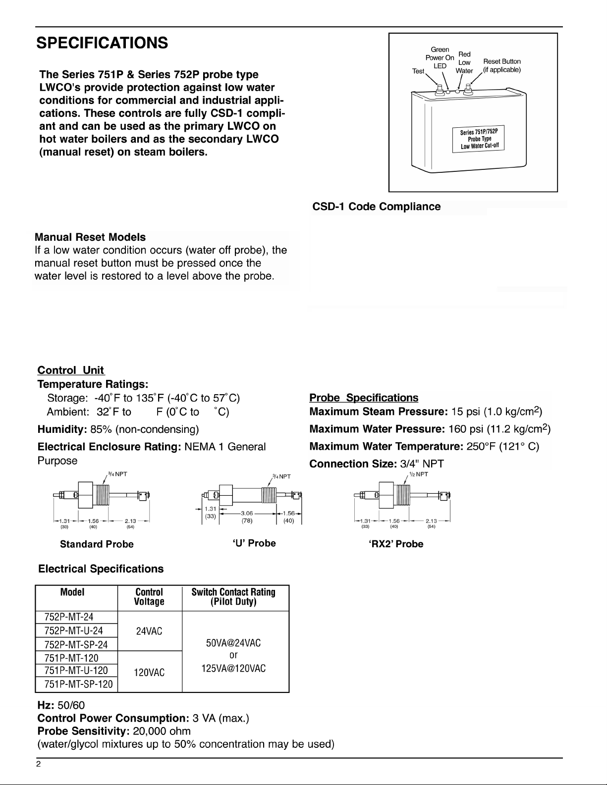
Manual Reset units follow CSD-1 Code Compliance.
120°
120°
49
49
On Manual Reset Units, if the control is in low water
On Manual Reset Units, if the control is in low water
condition (water is off the probe) and there is a sudden
condition (water is off the probe) and there is a sudden
power interruption, the control will remain in low water
power interruption, the control will remain in low water
condition (Burner Off) even if the power is restored. The
condition (Burner Off) even if the power is restored. The
Reset Button must be depressed to make the control
Reset Button must be depressed to make the control
back to function, after the water level is re-established
back to function, after the water level is re-established
to the probe.
to the probe.
Lock Out DelayLock Out Delay
When a low water condition occurs the burners turns off
When a low water condition occurs the burners turns off
and Red LED begins to blink. When the water level is
and Red LED begins to blink. When the water level is
restored to a level above the probe within 30 sec, the
restored to a level above the probe within 30 sec, the
boiler will return to the normal operation. If the water
boiler will return to the normal operation. If the water
level remains in low condition, control will go to a low
level remains in low condition, control will go to a low
water condition and Red LED will be solid Red.
water condition and Red LED will be solid Red.
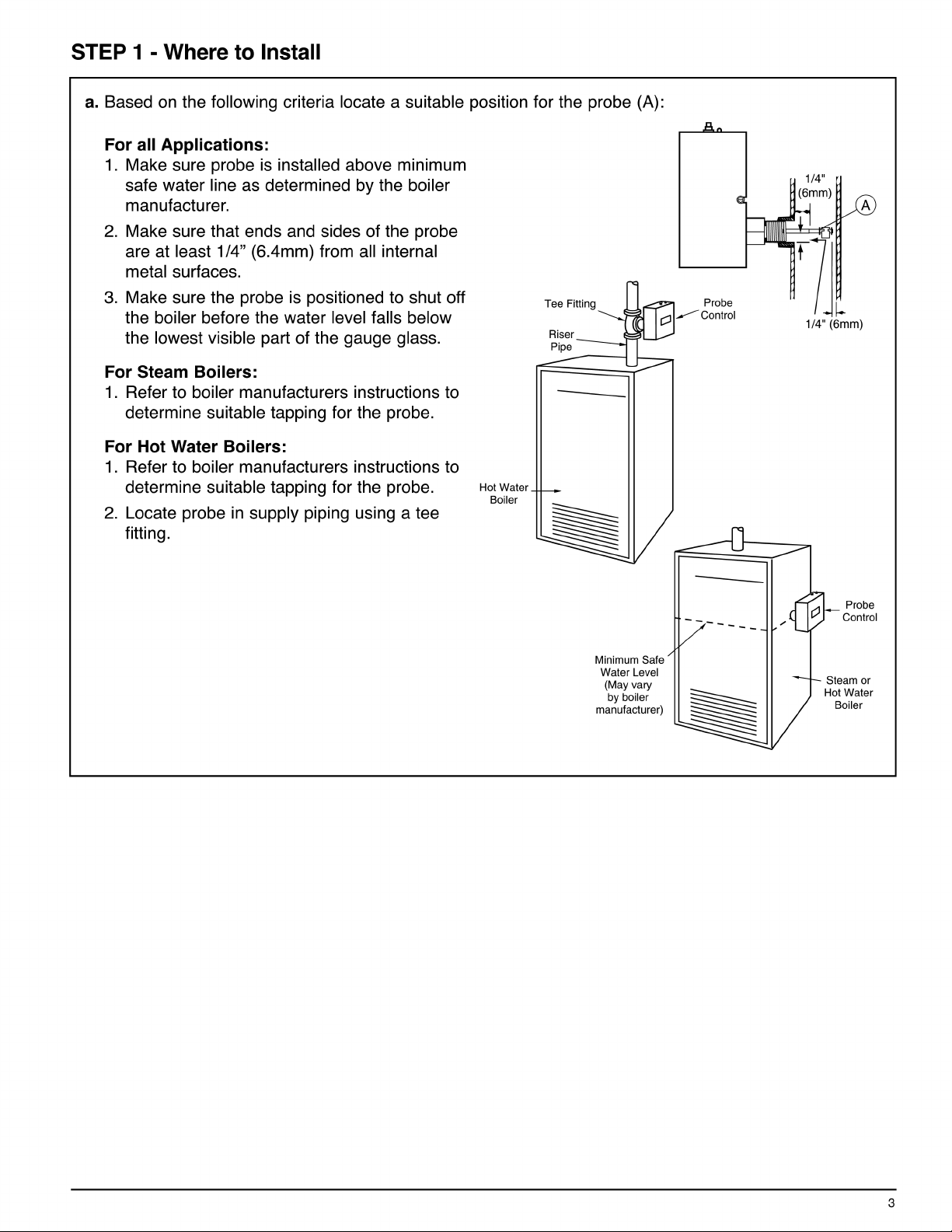
Page 3
Page 4

Page 5

Ground WireGround Wire
GND
PROBE
Page 6

Connect a wire from Terminal 5 to the next safety
Connect a wire from Terminal 5 to the next safety
device of the Burner's safety circuit, such as
device of the Burner's safety circuit, such as
thermostat, gas valve, limits, etc.
thermostat, gas valve, limits, etc.
Connect wire from end of Burner circuit to Terminal 2.Connect wire from end of Burner circuit to Terminal 2.
Connect hot wire from the separate power supply to Terminal 3.Connect hot wire from the separate power supply to Terminal 3.
Connect a wire from Terminal 5 to the next safetyConnect a wire from Terminal 5 to the next safety
device in the circuit.device in the circuit.
•
•
Connect probe wire from probe to
Connect probe wire from probe to
"probe connection on PCB"
"probe connection on PCB"
•
•
Connect ground wire from "GND" connection
Connect ground wire from "GND" connection
on PCB to chasis green screw
on PCB to chasis green screw
HOT
HOT
NEUTRAL
NEUTRAL
ALARM
LIMIT
CIRCUIT
Page 7

STEP 6 - Testing and Diagnostic Procedures
Series 750 LWCO with Green Power On LED and Red Low Water LED
Start-Up
a. Before filling the system,
1. Upon initial power up, the Green and Red lights will flash
simultaneously 4 times.
2. The Green light will turn "ON".
3. Red LED will be flashing for 30 sec. and turn solid on afterward.
4. The burner will never turn "ON" during power up, if water is off
the probe.
b. Now fill the boiler with water.
(When water returns to the probe, nothing will happen until the manual reset button is depressed.)
1. After depressing manual reset button, the Green and Red lights will flash simultaneously 4 times.
2. Then the Green light will turn "ON" and the Red light will turn "OFF".
3. The burner will be "ON" as long as there is water on the probe.
Manually Testing Control
c. Slowly drain the boiler of water.
1. When the water drops off the probe, the Green light remains "ON".
2. The Red light starts flashing and the burner will turn "OFF", if water is off the probe.
Red LED will turn "OFF" and burner turns "ON" if water returns to probe during 30 sec.
Red LED will turn "ON" burner turns "OFF" if water below probe.
Testing Control Using "Test Button"
d. Depressing the test button with "water on probe." :
(Must depress and hold test button for 30 sec. to activate test cycle, Red LED will flash and Green is "ON".)
turn on the electric power to the boiler.
1.B oth Red and Green LEDs stay "ON" after test cycle is activated.
2. The burner will turn "OFF".
(Release test button. You must depress the manual reset button to unlock the low water cut-off.)
3. Then the Green light will turn "ON" and the Red light will turn "OFF", after Red and Green lights flash
simultaneously 4 times.
4. The burner will turn "ON" as long as there is water on the probe.
CSD-1 Compliance
On Manual Reset Units, if the control is in low water condition (water is off the probe) and there is a sudden
power interruption, the control will remain in low water condition (B urner Off) even if the power is restored.
The Reset B utton must be depressed to mak e the control back to function, after the water level is re-established
to the probe.
7
Page 8

base of the electrodebase of the electrode
© 2013 Xylem Inc. MM-283D December 2013 Part No. 210995
 Loading...