

Page 1
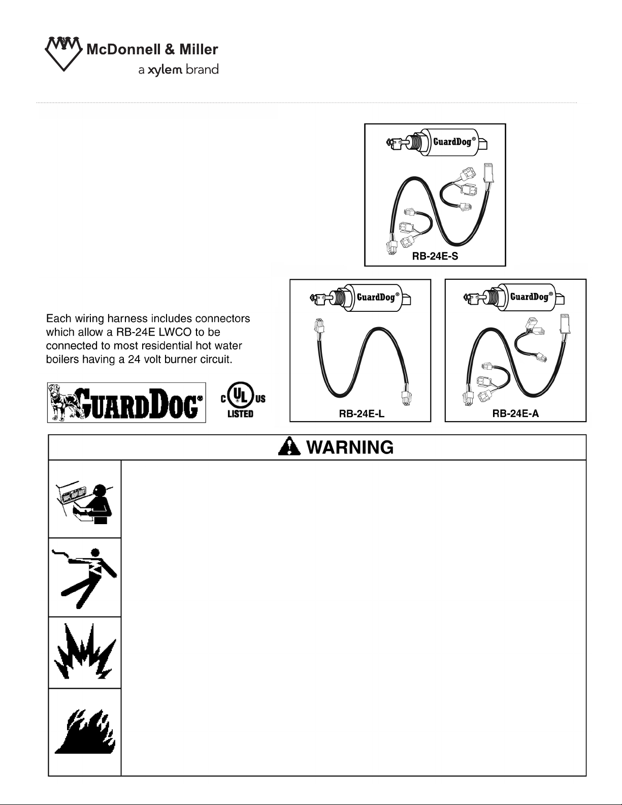
Model RB-24E-S
Model RB-24E-A
Model RB-24E-L
Conductance Type
Low Water Cut-Off
with Universal Wiring Harness
For Residential
24 VAC Hot Water Boilers
INSTRUCTION MANUAL
MM-277G
• Before using this product read and understand instructions.
• Save these instructions for future reference.
• All work must be performed by qualified personnel trained in the proper application, installation, and maintenance of plumbing, steam,hot water and electrical equipment and/or
systems in accordance with all applicable codes and ordinances.
• To prevent electrical shock, turn off the electrical power before making electrical connections.
• This low water cut-off must be installed in series with all other limit and operating controls
installed on the boiler. After installation, check for proper operation of all of the operating
controls, before leaving the site.
• We recommend that secondary (redundant) Low Water Cut-Off controls be installed on all
steam boilers with heat input greater than 400,000 BTU/hour.At least two controls should
be connected in series with the burner
should the boiler experience a
low water cut-offs should be
calibration and performance.
California Proposition 65 warning! This product contains chemicals known to the
•
state of California to cause cancer and birth defects or other reproductive harm.
Previous controls should never be installed on a new system. Always install new
•
controls on a new boiler or system.
Failure to follow this warning could cause property damage, personal inj ury or death.
CAUTION:
•
A more frequent replacement interval may be necessary based on the condition of
the unit at time of inspection. McDonnell & Miller s warranty is one (1) year from date
of installation or two (2) years from the date of manufacture.
low-water condition. Moreover, at each annual outage, the
dismantled, inspected, cleaned, and checked for proper
!
control circuit to provide safety redundancy protection
&
'
Page 2
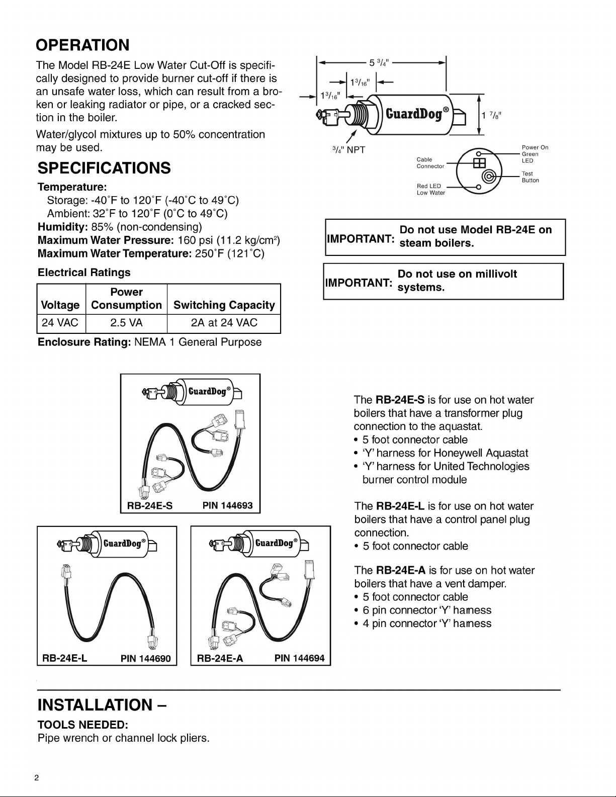
OPERATION
The Model RB-24E Low Water Cut-Off is specifically designed to provide burner cut-off if there is
an unsafe water
or
ken
tion
Water/glycol
may be used.
leaking radiator or pipe, or a cracked sec-
in
the boiler.
loss, which can result from a bro-
mixtures up to 50% concentration
SPECIFICATIONS
Temperature:
Storage: -40'F to 120'F (-40'C to 49'
Ambient: 32'F to 120'F (O'C to 49'C)
Humidity:
Maximum Water Pressure:
Maximum Water Temperature:
85% (non-condensing)
160 psi (11.2 kg/cm2)
250' F
C)
(121 'C)
3//
NPT
IMPORTANT: steam boilers.
Cable LED
Connector
=e;;=
R
ed
LED
Low Water
Do not use Model RB-24E on
On
~
~:ee
~
Test
Button
Electrical Ratings
Power
Voltage Consumption Switching Capacity
24VAC
Enclosure Rating:
2.5
VA
NEMA 1 General Purpose
RB-24E-S
2A at 24 VAC
PIN 144693
Do not use on
IMPORTANT:
The
boilers that have a transformer plug
connection to the aquastat.
• 5 foot connector cable
•
'V' harness for Honeywell Aquastat
• 'V' harness for United Technologies
burner control module
The
boilers that have a control panel plug
connection.
• 5 foot connector cable
systems.
RB-24E-S
RB-24E-L
is
for use on hot water
is
for use on hot water
millivolt
RB-24E-L
PIN 144690
INSTALLATION -
TOOLS NEEDED:
Pipe wrench or channel lock pliers.
2
RB-24E-A
PIN 144694
is
RB-24E-A
The
boilers that have a vent damper.
• 5 foot connector cable
•
6 pin connector 'V' hamess
• 4 pin connector 'V' hamess
for use on hot water
Page 3
STEP 1 - Electrical Wiring Options
A
'"'
.
~
",
~
To
prevent electrical shock,
•
This
low
the
water
boiler.
leaving
to
follow
After
•
on
before
Failure
cut-off
installation,
the
site.
this
warning
must
turn
be
could
off
the
installed
check
for
cause
electrical
a
WARNING
power
in
series
proper
property
with
operation
damage,
before making electrical
all
other
limit
and
of
all
of
personal
the
injury
operating
limit
connections.
controls
and
operating
or
death.
installed
controls,
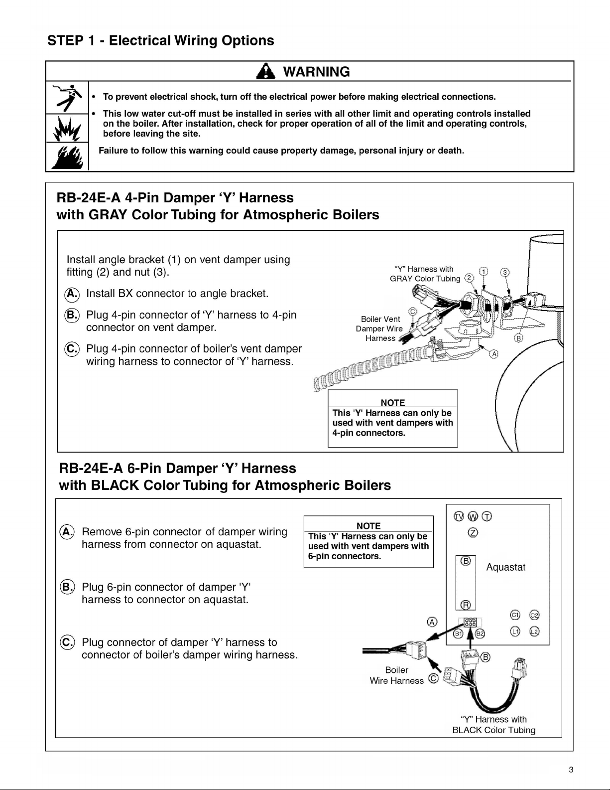
RB-24E-A 4-Pin Damper
with GRAY
Install angle bracket (1)
Color Tubing for Atmospheric Boilers
on
vent damper using
Harness
'Y'
fitting (2) and nut (3).
®
Install BX connector to angle bracket.
®
Plug 4-pin connector of 'Y' harness to 4-pin
connector
@
Plug 4-pin connector of boiler's vent damper
on
vent damper.
Boiler Vent
Damper Wire
Harness ·
wiring harness to connector of 'Y' harness.
NOTE
This
'Y' Harness can
with
vent
RB-24E-A 6-Pin Damper
Harness
'Y'
used
4-pin connectors.
with BLACK Color Tubing for Atmospheric Boilers
"Y" Harness with -
GRAY Color Tubing
..
~
only
dampers
~
with
be
.
~~I
~
..
If
Remove 6-pin connector of damper wiring
®
harness from connector
®
Plug 6-pin connector of damper 'Y'
harness to connector
©
Plug connector of damper 'Y' harness to
connector of
boiler's damper wiring harness.
on
on
aquastat.
aquastat.
NOTE
'Y'
This
used
6-pin connectors.
Harness can
with
vent
dampers
only
be
with
Aquastat
"Y" Harness
BLACK
Ceilor
with
Tubing
3
Page 4

STEP 1 - Electrical Wiring Options (continued)
RB-24E-S Transformer ‘Y’ Harness
with BLUE Color Tubing
A. Remove connector of boiler wiring
harness from boiler control transformer
connector.
B. Plug connector of boiler wiring harness to
connector of ‘Y’ harness with BLUE color
tubing.
C. Plug connector of ‘Y’ harness with BLUE
color tubing to boiler control transformer
connector.
Burner will not operate and
RB-24E red LED will blink if
wrong ‘Y’ harness is used.
NOTE
RB-24E-S Transformer ‘Y’ Harness
with GREEN Color Tubing
A. Remove connector of boiler wiring
harness from Aquastat transformer
connector.
B. Plug connector of boiler wiring
harness to connector of ‘Y’ harness with
GREEN color tubing.
C. Plug connector of ‘Y’ harness with GREEN
color tubing to Aquastat transformer
connector.
NOTE
Burner will not operate and
RB-24E red LED will blink if
wrong “Y” harness is used.
Page 5

RB-24E-L Connector
with Gray
a. Remove jumper plug from plug-in connector
on
control panel.
b. Plug connector of wiring harness into plug-in Connector
on
control panel.
Color Tubing for Control Panel Connection
o
locilinvar Knight
Control
Pane
So
l
o
il@r
5
Page 6

STEP 2 - Installing the Low Water Cut-Off
Determine where
If tappings are provided
1.
control must
minimum safe water
boiler manufacturer. If
safe water level
to
install the probe control based
on
the boiler, the probe
be
installed
in
a tapping above the probe control can
level, as specified
no
specified minimum Typical Installation Diagrams below.
is
designated, contact the
by
boiler manufacturer.
For all Application:
1. Make sure probe is installed above minimum
safe water line as determined by the boiler
TYPICAL INSTALLATIONS
manufacturer.
On
the
Boiler
2. Make sure that ends and side of the probe
(RECOMMENDED)
are at least 1/4 (6.4mm) from all internal
metal surfaces.
314
' (2
Omm) NP
Tappi
ng
~
Model RB -24 E
Low Water
Gul-oH
T
. _
.,
I
"
m
~
----
~~-
Hot Water
Minimum
Safe
Waler Level
(as
determined
by
OOilill'
the
manufacturer)
Boil
er
on
the following requirements:
2.
If
no
tapping
is
provided
be
on
installed
the boiler, the
in
a header or
the riser pipe above the boiler. Refer to the
NOTE
Make
sure
RB-24E
than
4 ft.)
to
be
connected.
In a Pipe Tee
Above
the
Optional
Isolation
Val\l~
(MUSIOO
inslaUed
above too)
A
1/4"
E
(6mm)
burner
Boiler
-
is
located
control
--I-+-H--I
To
close
so
the
System
t
,
C0
enough
harness
Circulating
/
Pump
314'
/
P1peToo
......
Hot
(no
can
(2
Omm)
NPT
RB
I>Jl<xlel
Low
Wate
Cut-off
Mjnirn~lm
Wat€rLevei
(as
by the bolter
mamlfacturer)
WalQf
r
Safe
determined
BolIQf
more
-24E
STEP 3 - Installing the Low Water Cut-Off
a.
Sparingly, apply pipe sealant to the external threads
of the probe(A}.
IMPORTANT:
Do
not use PTFE tape. Only use pipe sealant.
1
(D)
1/4"
(6mm)
Page 7

STEP 4 - Testing
a.
Before filling the system, turn
boiler. The low water cut-off's green "Power On" LED
should
"heat:' confirm that the burner
water
should
NOTE:
and then shut off to verify proper operation.
be
illuminated. With the room thermostat set
in
the system. The low water cut-off's
be
illuminated.
The burner will come
on
the electric power to the
will
not
operate without
red
on
briefly
(1
second or less)
on
LED
Fill the system with water. When water
b.
probe, the
low water cut-off's
red
LED
should turn
is
just above the
c. Check and confirm that the boiler's thermostat, burner and
safety
before
Check the threaded connection of the low water cut-off for
d.
limits are operating properly after filling system and
leaving the site.
leakage. Tighten, if necessary.
Testing Control Using "Test
Pressing the "Test
a.
Press and hold "test button" while burner
b. The burner
c. Release the test button and the
provided that the boiler water
Button"
interrupts
should turn OFF and
Button"
the probe
red
red
light should turn off and the boiler should turn
in
contact with the probe.
circuit
is
running.
light turn
ON
INSTALLATION COMPLETE
off.
which
if burner
Cable
Connector
Red LED
Low Water
simulates water
is
wired correctly.
o-....."",.~--
__
~I-+-
off
the probe.
on
Power
Green
LED
Test
Button
On
Page 8

TROUBLESHOOTING:
If
control
1. Check to
2. Re-check all wiring to ensure proper connections as specified
wiring diagrams.
3. Check to ensure that tape has not been used
the boiler.
4. Check the quality of the boiler water to ensure adequate conductance.
fails
to
operate, perform the
be
sure that the water level
following
in
the boiler is at or above the level of the probe.
diagnostic
on
the threaded connection of the probe to
checks.
in
boiler manufacturers
Boiler
• Turn off boiler and check boiler wiring connections.
• Turn off boiler, drain boiler and remove control to check if the tip of the probe
Boiler
• Make sure water is above the level of the probe.
• Make sure probe is installed
• Check boiler wiring connections.
Boiler
• Problem is wrong transformer 'V' harness.
• Turn off boiler and install correct transformer 'V' harness .
Does Not Turn
a metal surface.
Does Not Turn
Does Not Turn
Off
(when water
is
ON
in
a location where
ON
and RB-24E Red LED
below probe)
an
blinking
air pocket cannot develop.
MAINTENANCE
SCHEDULE:
• Test the
• Remove and
• Replace the
low
water
inspect
low
water
cut-off
annually
or
more frequently.
the self-cleaning probe every 5 years.
cut-off
every 15 years.
is
touching
NOTE
Clean probe by wiping with non-abrasive cloth and rinsing with clean water.
use sharp instruments
Replace Probe if:
PTFE
•
• Probe is loose.
Failure
insulator is cracked or worn.
to
foII owthis caution could cause
xylem
Let's Solve
to
Water
remove any accumulations
A
CAUTION
prope
Xylem Inc.
8200 N. Austin Avenue
Morton Grove, Illinois 60053
Phone: (847) 966-3700
Fax: (847) 965-8379
www.xyleminc.com/brands/mcdonnellmiller
McDonnell & Miller is a trademark of Xylem Inc. or one of its subsidiaries.
© 2013 Xylem Inc. MM-277G July 2013 Part No. 210589
of
rust or scale.
damage, personal injury
rty
DO
or
NOT
death.
 Loading...