

Page 1
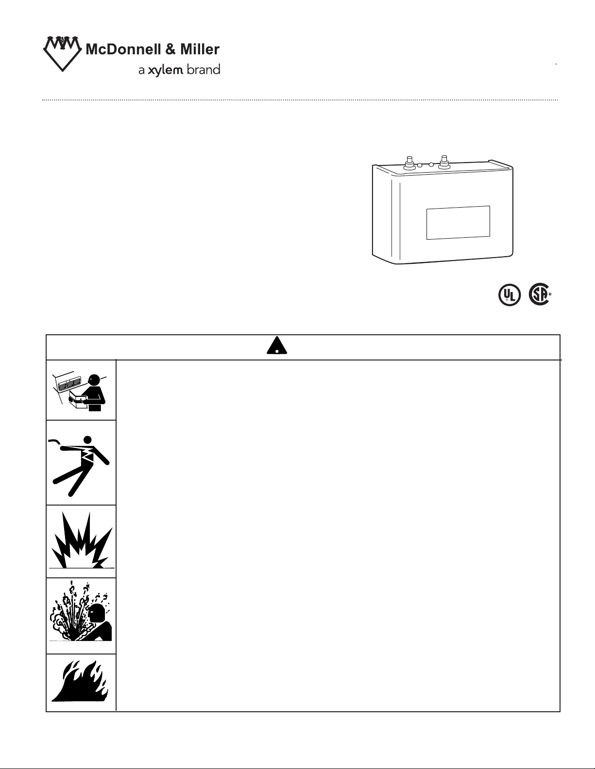
Model 750-HW-MT-120
5-1/2"
M
odel
7
5
0
-
HW
-MT
-
12
0
P
r
ob
e
T
y
pe
H
i
gh
W
a
t
er
Con
t
r
o
l
Uni
t
Probe Type High Water
Manual Reset Control Unit
Applications:
Conductance type control for steam boilers
when a manual reset high water alarm or
cut-off is required.
INSTRUCTION MANUAL
MM-273E
Model 750-HW-MT-120
Control Unit
!
WARNING
• Before using product, read and understand instructions.
N
O
I
T
U
CA
G
IN
N
R
WA
• Save these instructions for future reference.
• All work must be performed by qualified personnel trained in the proper application, installation,
and maintenance of plumbing and electrical equipment and/or systems in accordance with all
applicable codes and ordinances.
• Boiler manufacturer schematics should always be followed. In the event that the boiler
manufacturer’s schematic does not exist, or is not available from the boiler manufacturer,
refer to the schematics provided in this document.
• To prevent serious burns, allow the control and surrounding equipment to cool to 80˚F (27˚C)
and allow pressure to release to 0 psi (0 bar) before servicing.
• To prevent an electrical fire or equipment damage, electrical wiring insulation must have a
rating of 167˚F (75˚C) if the liquid's temperature exceeds 180˚F (82˚C).
• This control can be installed in series with all other limit and operating controls installed
on the boiler. After installation, check for proper operation of all the limit and operating
controls, before leaving the site.
• When using mixed voltages, do not jumper from terminal 1 to terminal 3.
• To prevent electrocution, when the electrical power is connected to the control, do not touch
the terminals, or electrical wires.
• To prevent electrical shock, turn off the electrical power before making electrical connections.
•
California Proposition 65 warning! This product contains chemicals known to the
state of California to cause cancer and birth defects or other reproductive harm.
Previous controls should never be installed on a new system. Always install new
•
controls on a new boiler or system.
Failure to fo
llow this warning could cause property damage, personal injury or death.
CAUTION:
A more frequent replacement interval may be necessary based on the condition of
•
the unit at time of inspection. McDonnell & Miller's warranty is one (1) year from date
of installation or two (2) years from the date of manufacture.
Page 2
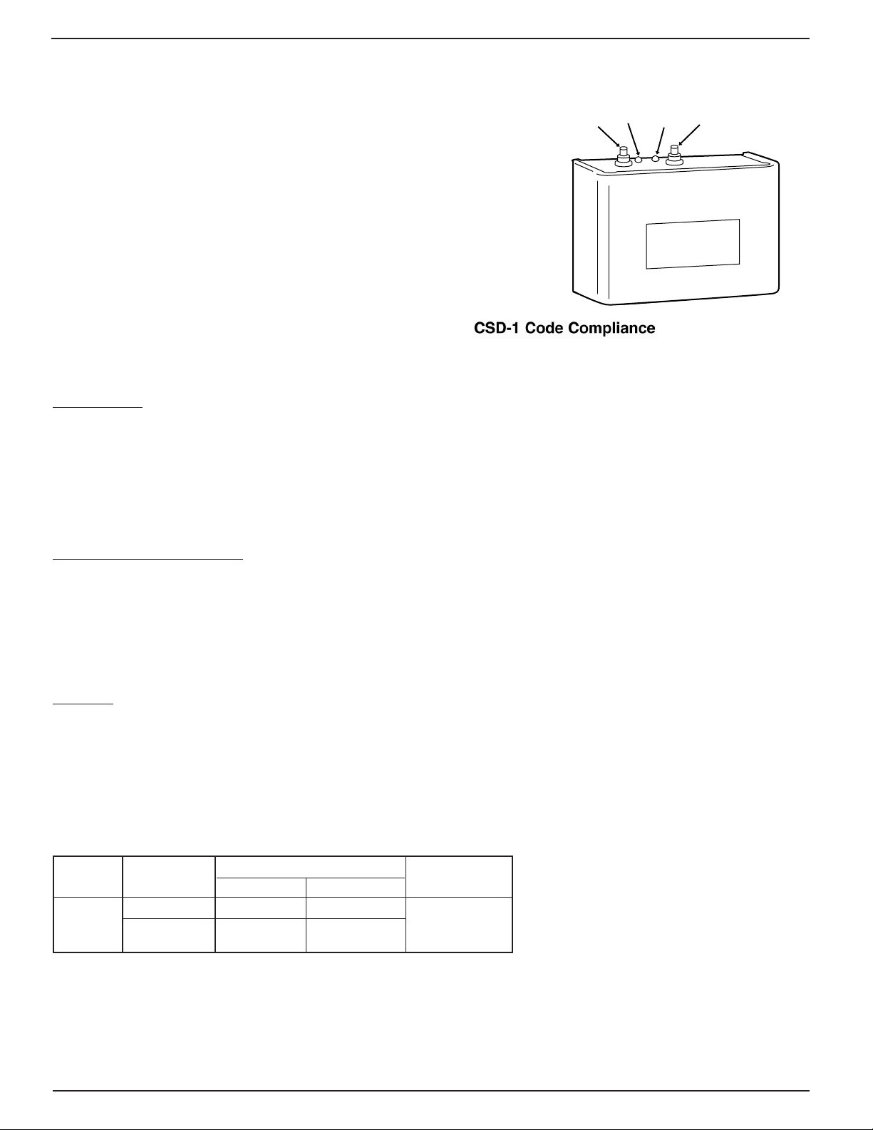
SPECIFICATIONS
The Model 750-HW-MT-120 control provides continuous protection
against a high water condition in steam boilers. It can be used to
interrupt the burner circuit to turn off the burner, interrupt the
feedwater pump circuit to turn off the pump, or both. The control
can also be used to provide an alarm (light, horn or both) when a
high water condition occurs. The manual reset function will require
that the unit be reset after water has dropped below the level of
the probe.
Manual Reset
If a high water condition occurs (water is on the probe),
the Burner will turn Off. The Manual Reset button must
be pressed to make the control back to function after the
water level drops below the probe.
Control Unit
Temperature Ratings:
Storage: -40˚F to 135˚F (-40˚C to 57˚C)
Ambient: 32˚F to 120˚F (0˚C to 49˚C)
On Manual Reset Units, if the control is in high water
condition (water reaches the probe) and there is an
interruption of electric power, the Burner will remain off
even if power is restored. The Reset button must be
depressed to make the control back to function after
the water level drops below the probe.
T
est
Green
Power On
R
ed
High
Water
75
Model
Type
robe
P
5-1/2"
ontr
C
Reset Button
-
T
HW-M
0-
Water
igh
H
l Unit
o
120
Humidity: 85% (non-condensing)
Electrical Enclosure Rating: NEMA 1 General Purpose
RS-1-BR1 Remote Sensor
Maximum Steam Pressure: 250 psi (17.6 kg/cm2)
Maximum Water Pressure: 250 psi (17.6 kg/cm
2
)
Maximum Water Temperature: 406˚F (208˚C)
Electrical Enclosure Rating: NEMA 4X Watertight,
Corrosion Resistant
Connection Size: 1” NPT
RS-1-LP
Maximum Steam Pressure: 15 psi (1.0 kg/cm2)
2
Maximum Water Pressure: 160 psi (11.2 kg/cm
)
Maximum Water Temperature: 250˚F (121˚C)
Electrical Enclosure Rating: NEMA 1 General Purpose
Connection Size: 3/4” NPT
Electrical Specifications
Motor Switch Rating (Amperes)
Model Voltage Full Load Locked Rotor Pilot Duty
120 VAC
120 VAC 7.2 43.2
240 VAC 3.6 21.6
125 VA at
120 or 240 VAC
50 or 60 Hz
Control Voltage: 120 VAC
Hz: 50/60
Control Power Consumption: 3 VA (max.)
Probe Sensitivity: 20,000 ohm
2
Page 3
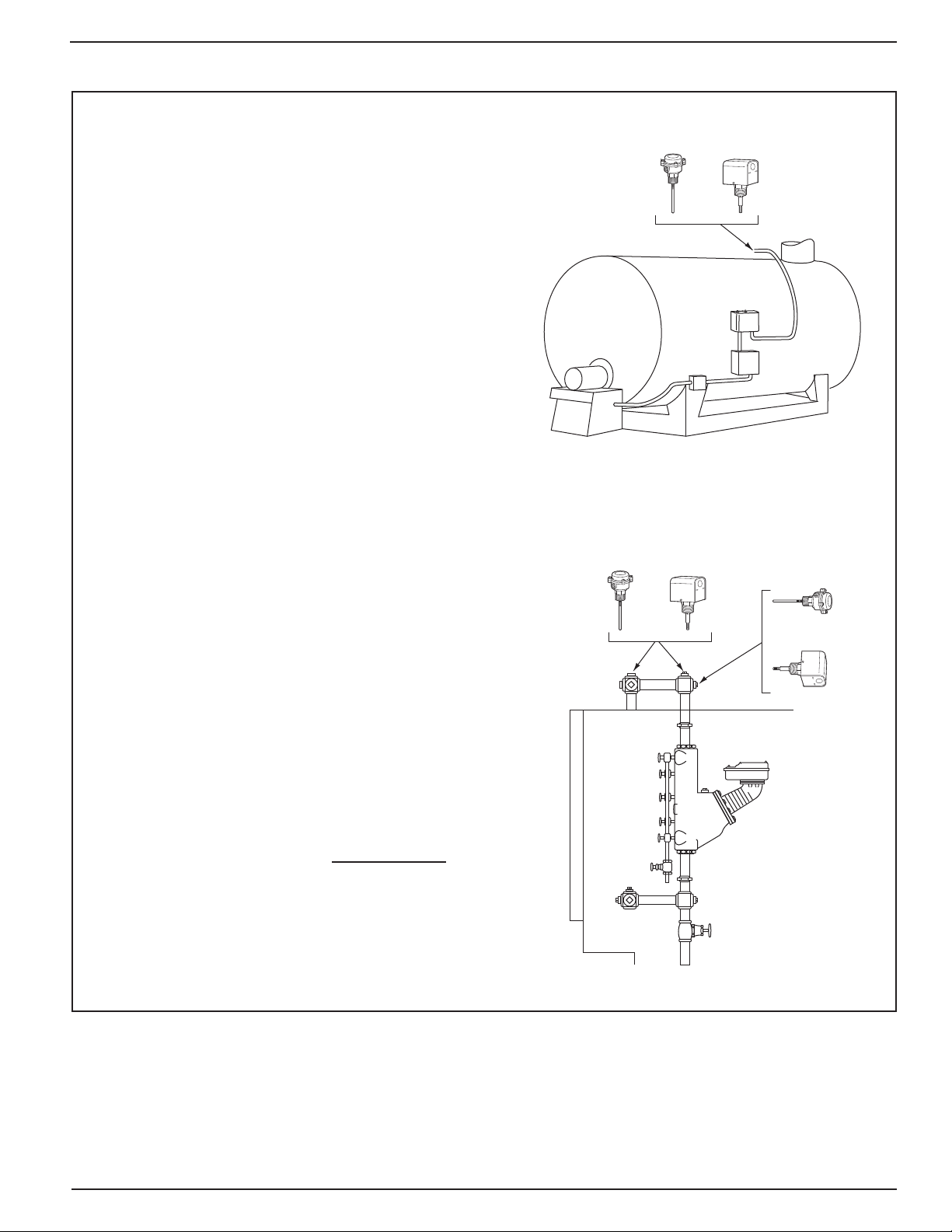
STEP 1 - Where to Install the Remote Sensors
o
r
or
or
Upright or Vertical
Position
Sideways or Horziontal
Position
Determine where to install the remote sensor (sold separately) based on the following requirements:
Option A
a. The Remote Sensor can be installed directly in a 1"
or larger tapping in the top of the boiler.
b. The probe of the RS-1-BR-1 Remote Sensor will
need to be cut to appropriate length based upon the
level where high water cutoff/alarm is desired.
c. The probe of the RS-1-LP Remote Sensor is
approximately 2" long therefore high water
cutoff/alarm will occur at that level.
d. There must be a minimum 1/4" (6.4mm) clearance
between the probe and any grounding surface inside
the boiler or pipe.
Option B
a. The Remote Sensor can be installed directly into the
1" fittings of the boiler’s equalizing piping.
b. If installed in the upright or vertical position:
• The probe of the RS-1-BR-1 Remote Sensor will
need to be cut to appropriate length based upon
the level where high water cutoff/alarm is desired.
• The probe of the RS-1-LP Remote Sensor is
approximately 2" long therefore high water
cutoff/alarm will occur at that level.
c. If installed in the sideways or horizontal position:
• The probe of the RS-1-BR-1 Remote Sensor
cannot exceed 4" in length.
NOTE: The Remote Sensors SHOULD NOT be
installed in equalizing piping that is smaller than
1" NPT.
d. There must be a minimum 1/4" (6.4mm) clearance
between the probe and any grounding surface
inside the boiler or pipe.
3
Page 4

STEP 2 - Installing the Remote Sensor
For the Model RS-1-BR-1 sensors, only:
a. Cut the probe (purchased separately) to desired length.
Screw, clockwise, the threaded stainless steel probe
extension (A) into the remote sensor (B). Carefully tighten
the locking nut to approximately 1 ft•lb (1.7 N•m). Do not
cut the clear plastic protective tube.
For All Remote Sensors
b. Apply a small amount of pipe dope to the first
threads (L) of the remote sensor.
B
A
IMPORTANT: Do not use PTFE tape or thread
sealant.
c. Insert the remote sensor (B) into the boiler
tapping (M) as determined in Step 1.
d. Using a wrench (N), tighten the brass hex
adapter (P) on the remote sensor (B) to
approximately 63 ft•lb (85 N•m). DO NOT
TIGHTEN BY TURNING THE SENSOR
HOUSING.
B
B
1/4" MIN. (6.4 mm)
P
OR
L
L
M
1/4" MIN. (6.4 mm)
N
4
Page 5

STEP 3 - Installing the Control Box
a. Using the flatblade screwdriver or nut driver (C),
loosen the two (2) screws (D) and remove
cover (E).
IMPORTANT: To protect control from damage
caused by liquid or debris, mount as shown with
buttons on top.
D
x2)
(
M
od
e
l 7
5
0
-
HW-
MT
-1
2
0
Pr
o
be
T
yp
Co
ntr
e
Hig
h
Wa
te
r
o
l Un
it
E
C
b. Using the four (4) 3/16" (4.8mm) mounting
holes (F), attach the control (G) to the boiler
jacket, entry plate, or other suitable location.
NOTE: Mounting hardware is not included.
STEP 4 - Electrical Wiring
IMPORTANT
!
Boiler manufacturer schematics should always be
followed. In the event that the boiler manufacturer’s
schematic does not exist, or is not available from
the boiler manufacturer, refer to the schematics
provided in this document.
• Mount Control Box in a suitable location near
the boiler’s main electrical panel.
NOTE
Boiler sight glass must be visible from location of
Control Box and must be within 25 feet of Control
Body.
GND
F
(x4)
WARNING
!
To prevent an electrical fire or equipment damage,
electrical wiring must have a rating of 167˚F (75˚C) if the
liquid's temperature exceeds 180˚F (82˚C).
Failure to follow this warning could cause property
damage, personal injury or death.
PROBE
RS1-BR-1
SENSOR
G
a. Remove the sensor housing cover (Q).
1. For Model RS-1-BR-1, using a flathead
screwdriver (R), remove the four (4) screws
and separate the housing cover (Q) from the
sensor (B).
2. For Model RS-1-LP, using a flathead screw-
driver or nut driver (R), loosen the two (2)
screws and separate the housing cover (Q)
from the sensor (B).
R
Q
B
Model RS-1-BR-1
OR
Q
B
R
Model RS-1-LP
5
Page 6

• Install electrical conduit between Probe
Housing and Control Box.
NOTE
Wire must be 18 AWG stranded with glass braided
silicone jacket (UL 3071) suitable for high
temperature (200˚C) service.
NOTE
Refer to and follow local codes and standards
when selecting conduit and electrical fittings.
Wires from Probe Housing and Control Box must
be in their own conduit. If they are run in conduit
with other wires, there may be interference that
an affect the performance of the control.
c
b. For all wire connections to the terminal block (M).
1. Strip about 1/3" (8.5 mm) of insulation from
the wire.
2. Loosen the terminal screw (N), DO NOT
REMOVE, and move the wire clamping plate
(P) back until the plate touches the back side
of the screw head.
3. Insert the stripped end of the wire under the
wire clamping plate (P) and securely tighten
the terminal screw (N).
RS1-BR-1
SENSOR
N
P
M
Wiring Diagram Legends
1. Bold lines indicate action to be taken in Step shown.
2. Dotted black lines indicate internal wiring.
Remote Sensor Wiring:
• Connect wire from probe end to Terminal
• Connect wire from remote sensor green ground
screw to
Terminal connection "GND" on PCB.
Control Wiring:
• Connect 120V hot wire to terminal 1
• Connect 120V neutral wire to terminal 2
• Connect jumper wire from Terminal 1 to
Terminal 3
• Connect wire from beginning of limit circuit
(thermostat, gas valve, limits, etc.) to terminal 5
• Connect wire from end of limit circuit to terminal 2
connection "PROBE" on PCB.
GND
WHITE
PROBE
1
HOT
2
NEUTRAL
3 4 5
ALARM
Note:
Contact positions shown
with water off probe
Limit Circuit
6
Page 7

c. Secure the sensor housing cover (Q).
1. For model RS-1-BR-1, using the flatblade screw-
driver (R), tighten the four (4) screws into the
housing (Q) to approximately 3 ft•lb (4 N•m).
2. For model RS-1-LP, using the flatblade screw-
driver or nut driver (R), tighten the two (2) screws
into the
housing (Q) to approximately 2 ft•lb (2.6 N•m).
d. Secure the control housing cover by using the
flatblade screwdriver or nut driver (R) to tighten the
two (2) screws (D) to approximately 2 ft•lb (2.6 N•m).
R
Q
R
Q
OR
Model RS-1-BR-1 Model RS-1-LP
D
(x2)
Mo
d
el
7
5
0
-H
W
-M
T
-
1
20
Pro
b
e
T
y
p
e
H
i
g
h
W
a
t
e
r
C
on
trol Uni
t
R
STEP 5 -Testing and Diagnostic Procedures
Start-Up
a. Before filling the system, turn on the electric power to the boiler.
1.
Upon initial power up, the Green and Red lights will flash simultaneously
4 times.
2. The Green light will turn "ON".
3. The Red light will turn "OFF" and the burner will turn “ON” as long
as there is water off the probe.
Test
Green
Power On
Manually Testing Control
b. Slowly fill the boiler with water.
1. When water touches the probe, the Green light will remain "ON".
2. The Red light will turn “ON” and the burner will turn “OFF”, when
water touches the probe.
Testing Control Using "Test Button"
c. Depressing test button with "water off probe”
(Must depress and hold test button to activate test cycle.)
1. When test cycle is activated the Red and Green lights will flash simultaneously
2. The Red light will turn "ON".
3. Burner will turn "OFF".
4. The Green light while the test button is depressed.
(Release test button. You must depress the manual reset button to unlock the high water cut-off.)
5. After depressing manual reset button, the Green and Red lights will flash simultaneously 4 times.
6. Then the Green light will turn "ON" and the Red light will turn "OFF".
7. The burner will turn "ON" if
stays "ON"
the water is off the probe.
twice.
Red
High
Water
el
d
Mo
be Type High
o
Pr
5-1/2"
50-HW-MT-1
7
ntrol U
o
C
Reset Button
0
2
r
e
t
a
W
it
n
7
Page 8

McDonnell & Miller
Troubleshooting
If control fails to operate as required, perform the following diagnostic checks:
1. Check to be sure that the water level in the boiler is below the probe.
2. Re-check all wiring to ensure proper connections as specified in boiler manufacturer’s wiring diagrams
or these instructions.
3. Check to ensure that PTFE tape has not been used on the threaded base of the remote sensor
the boiler.
4. Re-check the electrical ground connection for the remote sensor and control unit.
to
MAINTENANCE
SCHEDULE:
• Inspect probe annually or more frequently for scale build-up and clean or replace if necessary.
Make certain there is no scale or build-up on the probe or its white PTFE insulator. Be careful not to damage
the PTFE insulator.
CAUTION
!
Replace Probe if:
• PTFE insulator is cracked or worn.
• Probe is loose.
Failure to follow this caution could cause property damage, personal injury or death.
• Replace probe every 10 years. More frequent replacement of the probe is required if it is used in locales
where significant water treatment is required, or in applications with high make-up water requirements.
• Replace the control unit every 15 years.
NOTE
Clean probe by wiping with non-abrasive cloth and rinsing with clean water. DO NOT
use sharp instruments to remove any accumulations of rust or scale.
Xylem Inc.
8200 N. Austin Avenue
Morton Grove, Illinois 60053
Phone: (847) 966-3700
Fax: (847) 965-8379
www.mcdonnellmiller.com
McDonnell & Miller is a trademark of Xylem Inc. or one of its subsidiaries.
© 2013 Xylem Inc. MM-273 2013
E
December
Part No.
210564
 Loading...