

Page 1
Replacement Snap Switch Assembly
!
SWA-42S
For Series 42S Low Water Cut-Off/
Pump Controllers (All Models)
INSTRUCTION MANUAL
MM-244B
Replacement Switch Assembly
WARNING
TION
AU
C
G
NIN
R
A
W
• Before using this product read and understand instructions.
• Save these instructions for future reference.
• All work must be performed by qualified personnel trained in the proper application, installation, and maintenance of plumbing, steam, and electrical equipment and/or systems in
accordance with all applicable codes and ordinances.
• To prevent serious burns, the boiler must be cooled to 80˚F (27˚C) and the pressure must be
0 psi (0 bar) before servicing.
• To prevent electrical shock, turn off all sources of electrical power before servicing unit.
• This low water cut-off must be installed in series with all other limit and operating controls
installed on the boiler. After servicing unit, check for proper operation of all of the limit and
operating controls before leaving the site.
• To prevent a fire, do not use this low water cut-off to switch currents over 7.4A, 1/3 Hp at
120 VAC or 3.7A, 1/3 Hp at 240 VAC, unless a starter or relay is used in conjunction with it.
Failure to follow this warning could cause property damage, personal injury or death.
Page 2

Verify that you have the Correct Replacement Switch Assembly Model
IMPORTANT:
• Installation of an incorrect switch-assembly could cause damage to the boiler and/or boiler system.
• Modification of the switch assembly before or after installation could cause damage to the boiler
and/or boiler system.
• Series 42S Replacement Snap Switch Assemblies are not interchangeable with Series 42 Mercury Switch
Replacement Assemblies.
• Series 42S Replacement Snap Switch Assemblies are not interchangeable with Series 150S Snap Switch Replacement
Assemblies, nor with Series 150 Mercury Switch Replacement Assemblies.
For Model Repl. Switch
Model No. Description
42S
42S-A SWA-42S Snap-action
42S-N switch assembly
42S-HD
Model SWA-42S
P/N 310488
2
Page 3
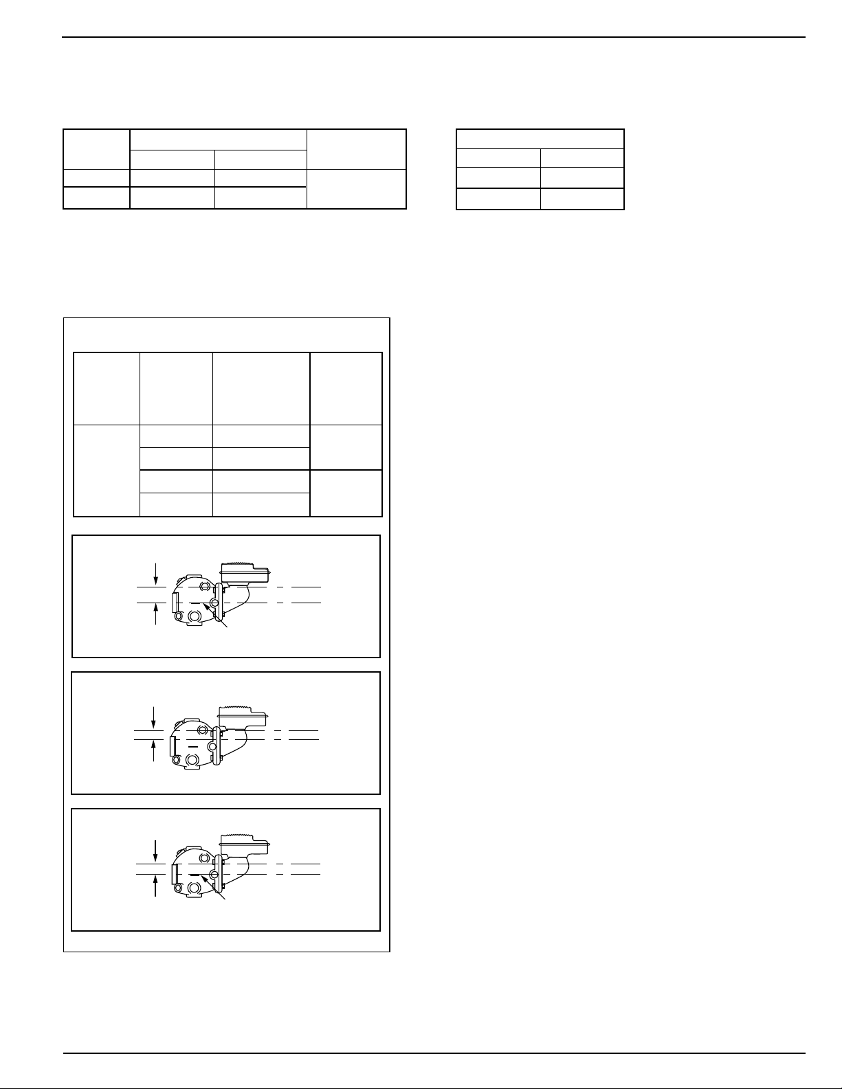
BURNER
ON
BURNER
OFF
NORMAL BOILER
WATER LINE
BURNER
CUT-OFF LEVEL
AT CAST LINE
7/8
" (22mm)
PUMP
OFF
BURNER
OFF
NORMAL BOILER
WATER LINE
BURNER
CUT-OFF LEVEL
AT CAST LINE
1 3/8
" (35mm)
PUMP
OFF
PUMP
ON
NORMAL BOILER
WATER LINE
3/4
" (19mm)
OPERATION
Maximum Pressure: 50 psi (3.5 kg/cm2)
Electrical Ratings
Pump Circuit Rating (Amperes)
Voltage Full Load Locked Rotor Pilot Duty
120 VAC 7.4 44.4
240 VAC 3.7 22.2
345 VA at
120 or 240 VAC
Settings and Differential Pressures
Values are ±1/8” (3.2mm).
Series 42S
Approximate
Distance Above
Cast Line Differential
Pressure
50 psi
(3.5 kg/
cm2)
Setting In. (mm) In. (mm)
Pump Off 1
Pump On
Burner On
3
/8 (35)
5
/8 (16)
7
/8 (22)
3
/4 (19)
7
/8 (22)
Burner Off 0 (0)
Motor Horsepower
Voltage Hp
120 VAC
1/3
240 VAC 1/3
3
Page 4
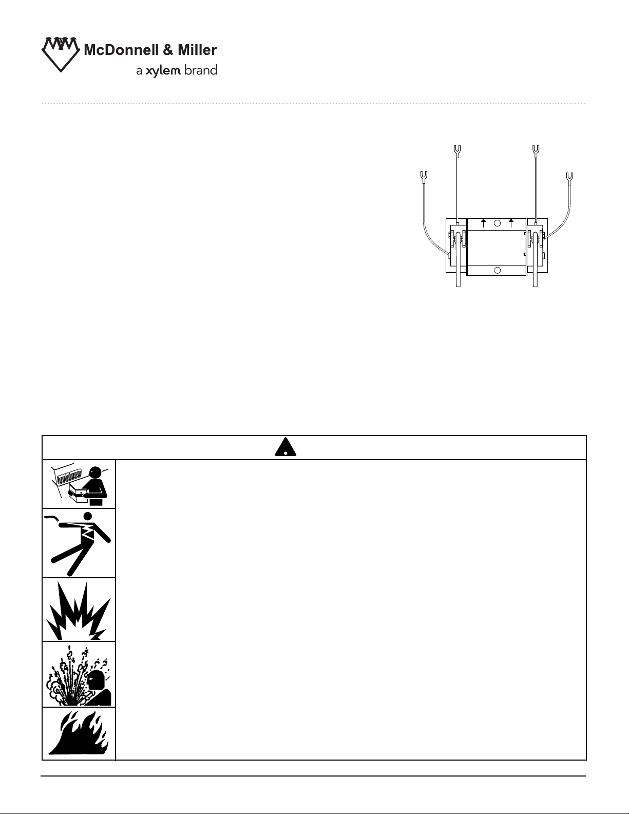
LOW WATER
CUT-OFF
TERMINALS
BURNER
SWITCH
PUMP
SWITCH
PUMP CIRCUIT
TERMINALS
OFF
ON
A
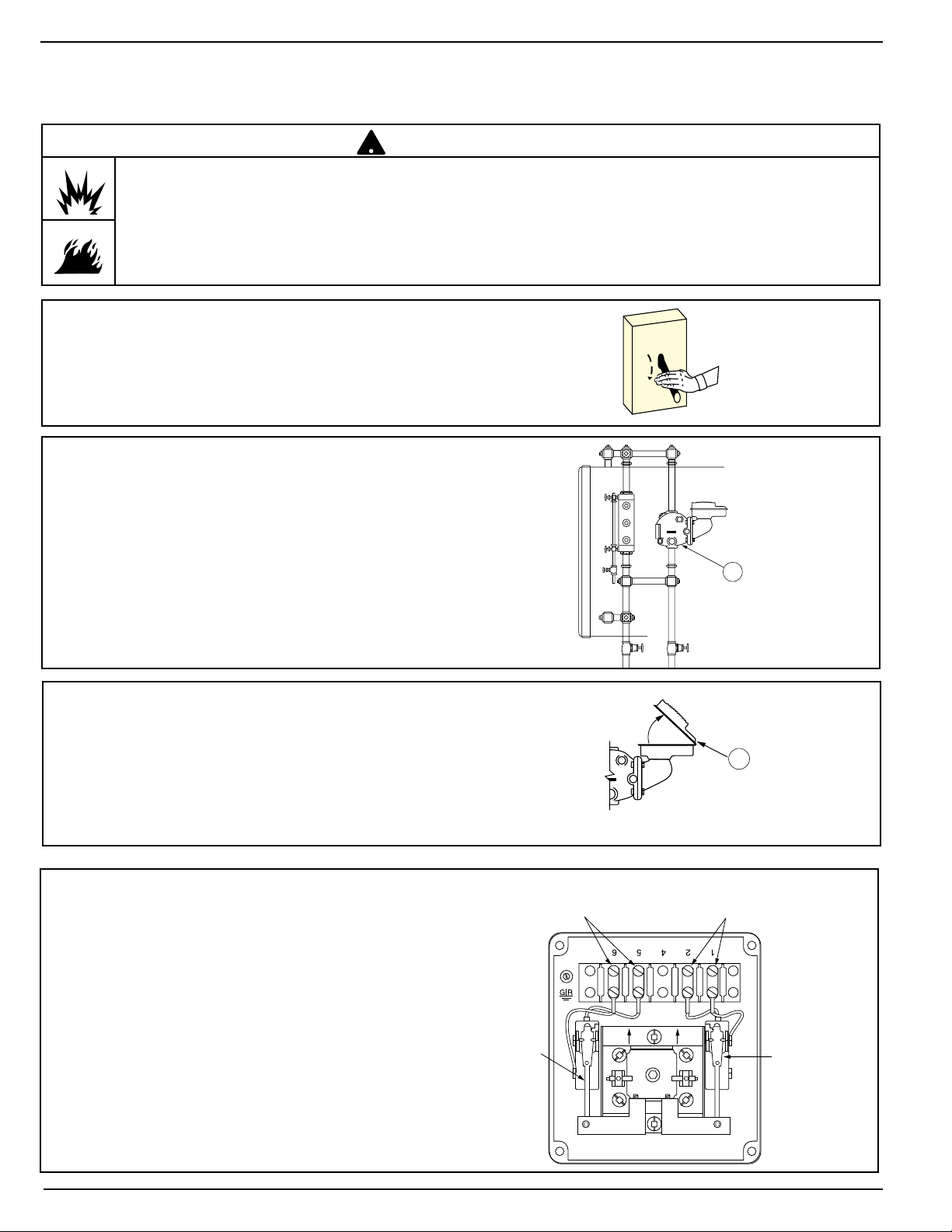
INSTALLATION –
!
SECTION 1 - Switch Bracket Replacement
WARNING
• To prevent electrical shock, turn off the electrical power before making electrical connections.
• This low water cut-off must be installed in series with all other limit and operating controls installed on the
boiler. After installation, check for proper operation of all of the limit and operating controls, before leaving
the site.
Failure to follow this warning could cause electrical shock, an explosion and/or a fire, which could result in
property damage, personal injury or death.
1. Turn the boiler off.
2. Allow the boiler to cool to 80˚F (27˚C) and
release the boiler pressure to 0 psi (0 bar).
Drain water in the boiler to a level which is
below the float chamber (A).
3. Remove the cover (B).
4. Mark and remove the pump switch
and burner/alarm switch wires from
terminal block.
B
4
Page 5

B
A
C
C
Terminal Connection Reference Chart
Product Switch 1 2 4 5 6
2 Wire Blue Orange
42S Pump
2 Wire White Red
Burner
5a. Locate the actuator assembly (A) and the
two fillister head screws (B) which secure
it to the bearing of the control.
b. Clean the inspection lacquer out of the
screw slots in the two fillister head
screws.
c. Remove the two screws holding the actu-
ator assembly in place using a flat head
screwdriver. Remove actuator assembly
and place aside for reinstallation.
Terminal Connection
6. Remove the two Torx®screws (C) holding
the switch bracket assembly in place using
®
a flat head screwdriver or a Torx
T30
wrench.
7. Take the new switch bracket assembly
out of the package and place the bagged
supplies to one side while discarding the
insert.
5
Page 6

C
C
8a. Install the new switch bracket assembly
B
A
LOW WATER
CUT-OFF
TERMINALS
PUMP
SWITCH
BURNER
SWITCH
PUMP
CIRCUIT
TERMINALS
into the junction box in the same orientation as the old switch bracket assembly
(i.e. with arrows on the bracket pointing
toward the terminal block).
b. Secure the new assembly with Torx
®
screws (C) and torque to 80 - 140 in. lb.
(92 - 161 cm. kg.).
9a. Reaffix the actuator assembly using the
two fillister head screws (B) and torque to
30 - 40 in. lb. (34.5 - 46 cm. kg.).
b. Apply a drop of the supplied adhesive to
the threads of each fillister head screw.
10. Reconnect the pump switch and burner/
alarm switch wires to terminal block as
noted when disconnected and torque to
13 - 17 in. lb. ( 15 - 19.5 cm. kg.) (Refer
to "Terminal Connection Chart" on page
5 if unsure of proper switch to terminal
block wire connections).
11. Reattach the cover (B).
B
Proceed with normal operational checks of controls as described in Section 2; “Checking Switch Settings and
Adjusting Switch Setpoints at Operating Pressure”; or Section 3; “Checking Switch Settings at "0" Pressure”.
The pump or burner switch operating points should be within +/- 1/4" of those specified for your control.
6
Page 7

SECTION 2 - Checking Switch Settings and Adjusting Switch Setpoints at
D
3"
(76.2mm)
2"
(50.8mm)
1"
(25.4mm)
Casting
Cut-Off
Line
1"
(25.4mm)
TOP
RULER
LEVEL
Operating Pressure
IMPORTANT: All switches have fixed differentials.
Adjustment of switches referred to in Section 2 and
3 are all based upon Pump Off and Burner Off setpoints. The Pump On and Burner On setpoints are
not adjustable.
1. Cut out the "Switching Level Ruler" (page 11)
along the indicated lines.
We strongly recommend that you check the control at both the operating pressure and at 0 pressure. All boilers start at 0 psi regardless of the oper-
ating pressure.
The operating points will spread out as the pressure
goes up and shrink as the pressure goes down.
3"
(76.2mm)
2"
(50.8mm)
1"
(25.4mm)
Casting
Cut-Off
Line
1"
(25.4mm)
2a. Hold the ruler against the side of the
gauge glass in a position so the “Cast
Line” mark is on the same level as the
Cast Line on the float chamber of the
control (D) (a carpenter's level should be
used to insure the cast line on the float
chamber is at the same level as the one
on the ruler).
b. Once the ruler is properly positioned,
tape it to the gauge glass.
3a. Bring boiler up to normal operating pressure
and turn the pump off.
b. Remove the cover (B).
(Not to Scale. Template
located on page 11).
B
7
Page 8

F
ADD ADHESIVE HERE
BURNER
SET SCREW
BURNER
SWITCH
E
PUMP OFF
PUMP ON
BURNER
CUT-OFF LEVEL
AT CAST LINE
4 - Setting the Operating Points of the Burner Switch
4a. Slowly bring the boiler water level down to
the point at which the burner cuts off. If the
burner does not shut off automatically by the
time the water level reaches 3/8" (9.5mm)
below the cast line on the unit body, shut the
burner off manually.
4b. If the cut-off point does not match the one
shown in chart for the control (page 3) as
measured on the "Switch Level Ruler," using
an awl, dig the inspection lacquer out of the
socket in the set screw (E) above the burner
switch in the actuator assembly.
c. Using an Allen wrench with a 5/64" hex, turn
the screw 1/4 turn:
- clockwise when viewed from top (if the
“Burner Off” point is too high)
- counterclockwise when viewed from top
(if the “Burner Off” point is too low )
4d. Turn the pump back on, allowing the boiler
to fill with water.
4f. Repeat steps a. through d. as necessary to
match the Burner Off point specification for
your model.
8
Page 9

PUMP
ON
PUMP
OFF
BURNER
CUT-OFF LEVEL
AT CAST LINE
H
ADD ADHESIVE HERE
G
PUMP SET SCREW
PUMP SWITCH
PUMP
OFF
PUMP
ON
NORMAL BOILER
WATER LINE
3/4
" (19mm)
5 - Setting the Operating Points of the Pump Switch
5a. Slowly drain the water in the boiler until the
pump turns on. Allow pump to fill the boiler
and observe the point on the ruler where the
water level shuts off.
5b. If the Pump Off point does not match the
one shown in chart for the control (page 3)
and as measured on the "Switching Level
Ruler", dig the inspection lacquer out of the
socket in the set screw (G) above the pump
switch in the actuator assembly using an
awl.
c. Using an Allen wrench with a 5/64" hex, turn
the screw 1/4 turn:
- clockwise (if the “Pump Off” point is too
high when viewed from top)
- counterclockwise (if the “Pump Off” point
is too low when viewed from top)
5d. Slowly drain the water in the boiler until the
pump turns on. Allow pump to fill the boiler
and observe the point on the ruler where
the water level shuts off.
5e. Repeat steps 5a. through d. as necessary
to match the specified Pump Off point specification.
f. Apply one drop of adhesive (furnished) to
the set screw threads (H) above the pump
switch in the actuator assembly.
9
Page 10

RULER
CAST
LINE
LEVEL
3"
(76.2mm)
2"
(50.8mm)
1"
(25.4mm)
Casting
Cut-Off
Line
1"
(25.4mm)
TOP
SECTION 3 - Checking Switch Settings at 0 Pressure
PUMP OFF
PUMP ON
BURNER
CUT-OFF LEVEL
AT CAST LINE
BURNER
ON
BURNER
OFF
NORMAL BOILER
WATER LINE
BURNER
CUT-OFF LEVEL
AT CAST LINE
7/8
" (22mm)
IMPORTANT: All switches have fixed differentials. Adjustment of switches referred to in Sections 2 and 3 are
all based upon Pump Off and Burner Off setpoints. The Pump On and Burner On setpoints are not adjustable.
1. Find the "Switching Level Ruler" on page 11,
and cut it out along the indicated lines.
2. Hold the ruler against the side of the gauge glass
in a position so the Cast Line mark is on the same
level as the cast line on the float chamber of the
control (a carpenter's level should be used to
insure the cast line on the float chamber is on the
same plane as the one on the marker).
3"
(76.2mm)
2"
(50.8mm)
1"
(25.4mm)
Casting
Cut-Off
Line
1"
(25.4mm)
(Not to Scale. Template
located on page 11).
3. Once the marker is properly positioned, tape it to
the gauge glass.
4a. Drain the water level in the boiler until the pump
turns on. Note the level at which the pump turns on
and then turns off. Verify that pump settings are
acceptable.
b. Turn the pump off.
5a. Drain the water level in the boiler until the burner turns
off. Observe the burner off point.
b. Turn the pump back on and observe the Burner On
point as the boiler fills with water. In the case of manual
reset models, try resetting the burner switch as close as
possible to the Burner On point as shown in chart for
the control and as measured on the switch level ruler.
Verify that burner settings are acceptable.
10
Page 11

B
6. Reattach the cover (B).
7. Turn the boiler on.
TOP
3"
(76.2mm)
2"
(50.8mm)
1"
(25.4mm)
Casting
Cut-Off
Line
ON
OFF
CUT HERE
1"
(25.4mm)
Switch Level Ruler
Cut to actual size and attach to piece of
cardboard.
11
Page 12

1) The tissue in plants that brings water upward from the roots;
2) a leading global water technology company.
We’re 12,500 people unified in a common purpose: creating innovative solutions
to meet our world’s water needs. Developing new technologies that will improve
the way water is used, conserved, and re-used in the future is central to our work.
We move, treat, analyze, and return water to the environment, and we help people
use water efficiently, in their homes, buildings, factories and farms. In more than
150 countries, we have strong, long-standing relationships with customers who
know us for our powerful combination of leading product brands and applications
expertise, backed by a legacy of innovation.
Xylem
For more information on how Xylem can help you, go to www.xyleminc.com
Xylem Inc.
8200 N. Austin Avenue
Morton Grove, Illinois 60053
Phone: (847) 966-3700
Fax: (847) 965-8379
www.xyleminc.com/brands/mcdonnellmiller
McDonnell & Miller is a trademark of Xylem Inc. or one of its subsidiaries.
© 2012 Xylem Inc. MM-244B August 2012 Part No. 210527
 Loading...