

Page 1
WARNING
CAUTION
!
Replacement Head Mechanism
42S-HD
(Snap Switch)
Replacement head mechanisms can be installed without
disturbing existing equalizing connections or disassembly
of components, making repairs simple and easy.
INSTRUCTION MANUAL
MM-243D
Replacement Head Mechanism
WARNING
• Before using this product read and understand instructions.
• Save these instructions for future reference.
• All work must be performed by qualified personnel trained in the proper application, installation, and maintenance of plumbing, steam, and electrical equipment and/or systems in
accordance with all applicable codes and ordinances.
• To prevent serious burns, the boiler must be cooled to 80˚F (27˚C) and the pressure must be
0 psi (0 bar) before servicing.
• To prevent electrical shock, turn off the electrical power before making electrical connections.
• This low water cut-off must be installed in series with all other limit and operating controls
installed on the boiler. After installation, check for proper operation of all of the limit and
operating controls, before leaving the site.
• To prevent serious personal injury from steam blow down, connect a drain pipe to the
control opening to avoid exposure to steam discharge.
• To prevent a fire, do not use this low water cut-off to switch currents over 7.4A, 1/3 Hp at
120 VAC or 3.7A, 1/3 Hp at 240 VAC, unless a starter or relay is used in conjunction with it.
Failure to follow this warning could cause property damage, personal injury or death.
Page 2
NORMAL BOILER
WATER LINE
PUMP
OFF
BURNER
OFF
BURNER
“CUT-OFF LEVEL”
AT CAST LINE
1 3/8" (35mm)
CUT-OFF
LEVEL
NORMAL BOILER
WATER LINE
C
UT-OFF
LEVEL
PUMP OFF
PUMP ON
3/4" (19mm)
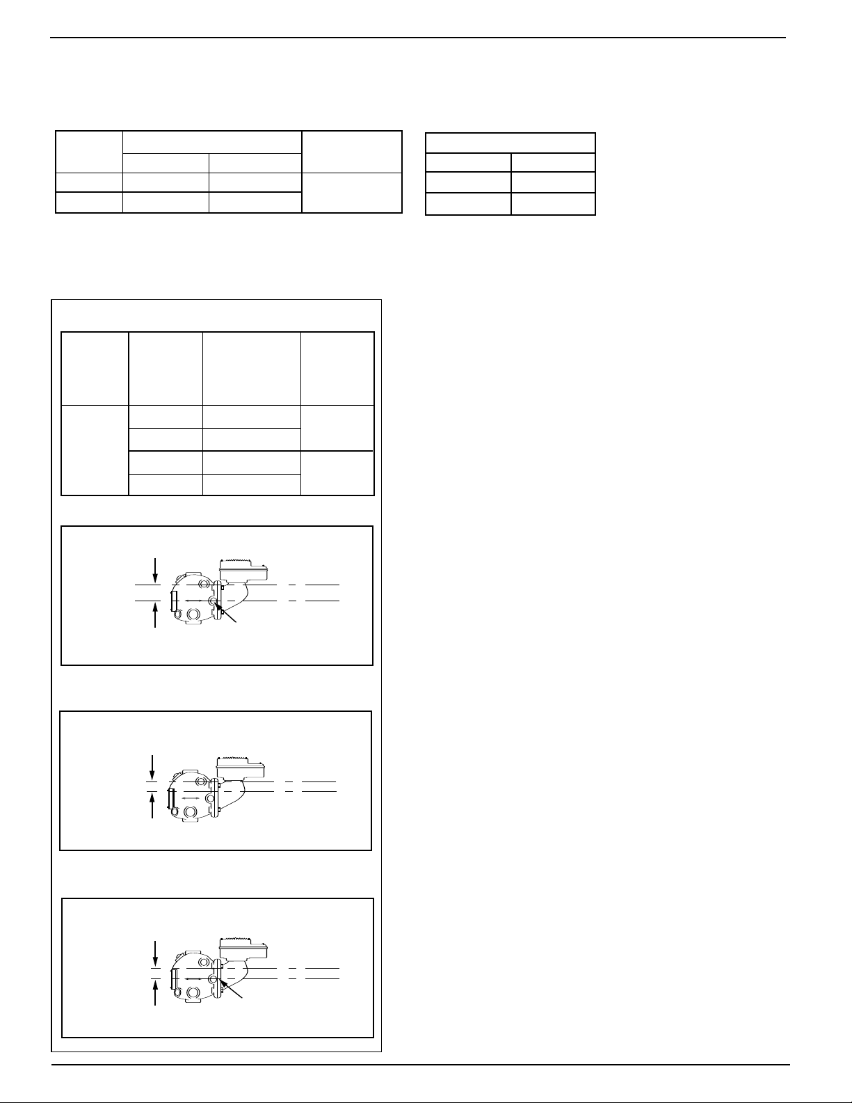
OPERATION
NORMAL BOILER
WATER LINE
BURNER
CUT-OFF LEVEL
AT CAST LINE
7/8" (22 mm)
BURNER ON
BURNER OFF
CUT-OFF
LEVEL
W
ARNI
NG
CAUTI
ON
!
Approved
®
Maximum Pressure: 50 psi (3.5 kg/cm2)
Electrical Ratings
Pump Circuit Rating (Amperes)
Voltage Full Load Locked Rotor Pilot Duty
120 VAC 7.4 44.4
240 VAC 3.7 22.2
45 VA at
3
120 or 240 VAC
Settings and Differential Pressures
Values are ± 8” (3.2mm).
Series 42S
Approximate
Distance Above
Cast Line Differential
Pressure
50 psi
(3.5 kg/
cm2)
Setting In. (mm) In. (mm)
Pump Off 13/8 (35)
Pump On
Burner On
5
/8 (16)
7
/8 (22)
3
/4 (19)
7
/8 (22)
Burner Off 0 (0)
otor Horsepower
M
Voltage Hp
20 VAC
1
1
240 VAC 1/3
/3
2
Page 3
A
B
C
D
F
E
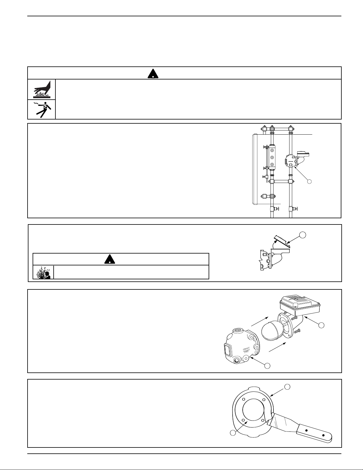
INSTALLATION –
!
!
TOOLS NEEDED:
O
ne (1) pipe wrench, one (1) flathead screwdriver, one (1) scraper, and one (1) 9/16" socket or wrench.
STEP 1 - Preparation
WARNING
• To prevent serious burns, the boiler must be cooled to 80˚F (27˚C) and the pressure must be 0 psi (0 bar)
before servicing.
• To prevent electrical shock, turn off the electrical power before disconnecting or making electrical connections.
Failure to follow this warning could cause property damage, personal injury or death.
a. Drain water in the boiler to a level which is
below the float chamber (A). Allow the boiler
to cool to 80˚F (27˚C) and release the boiler
pressure to 0 psi (0 bar).
b. Using a flathead screwdriver, remove the junction
ver (B). Disconnect, mar
x co
bo
supply wires and conduit connections
k, and remove the
.
CAUTION
There may be more than one source of power to the boiler.
e the existing head mechanism (C)
c. Remo
d. Using a scr
v
from the body (D).
aper, remove the old gasket (E).
Clean all debr
is from the float chamber
. The
gasket sealing surface (F) must be smooth
and clean.
3
Page 4

G
F
H
J
D
STEP 2 - Installing the Replacement Head Mechanism
A
B
C
D
F
E
!
!
a. Carefully remove the new replacement head
mechanism from the carton. Handle it carefully
to prevent damage to the float rod (G).
b. Align the bolt holes of the new head gasket
(H) on the sealing surface (F) of the control
body.
c. Install the ne
w replacement head (J) on the
body (D) by guiding the float into the control
body and aligning the bolt holes.
d. Using a wrench, insert the four (4) bolts and
tighten them to approximately 14-20 ft•lb
(19-27 N•m) in an alter
nating star pattern.
4
Page 5

B
STEP 3 - Electrical Wiring
!
K
1 2 5 6
Boiler feed pump off-
burner on.
1 2 5 6
Boiler feed pump on-
burner on.
1 2 5 6
Boiler feed pump on-
burner off.
• To prevent electrical shock, turn off the electrical power before making electrical connections.
• This low water cut-off must be installed in series with all other limit and operating controls installed on the
boiler. After installation, check for proper operation of all of the limit and operating controls, before leaving
the site.
Failure to follow this warning could cause electrical shock, an explosion and/or a fire, which could result in
property damage, personal injury or death.
Switch Operation
WARNING
Boiler feed pump off,
burner on.
Boiler feed pump on,
burner on.
1 2 5 6 1 2 5 6
a. Using a flathead screwdriver, remove the
junction box cover (B).
Boiler feed pump on,
burner off.
1 2 5 6
b. Following the appropriate wiring
diagram, (refer to page 6)
based on your application
requirements, and using BX
armored cable or Thinwall electrical metal tubing connector fittings, make electrical connections to the junction box (K).
Note: Follow local codes and standards when selecting the types of
electrical fittings and conduit to
connect to control.
IMPORTANT: There must be a
minimum space of 1/2” (13mm)
between connector fittings and
electrical live metal parts.
Snap Switches
(Series 42S)
5
Page 6

WIRING DIAGRAMS
LINE LOAD
12 56
12 56
LOAD
LINE
12 56
LOAD
LINE
12 56
SEE PUMP
CONTROL
CIRCUIT
TO BURNER CONTROL CIRCUIT
HOT
12 56
LOAD
LINE
SEE PUMP
CONTROL
CIRCUIT
B
B
!
K
1 2 5 6
Boiler feed pump off-
burner on.
1 2 5 6
Boiler feed pump on-
burner on.
1 2 5 6
Boiler feed pump on-
burner off.
Low Water Cut-Off Only
1. Main Line Switch - For burner circuits within the
switch’s electrical rating.
Pump Control Only
1. Install a starter or relay in pump control circuit,
as shown, to prevent damage to snap switch
and help insure proper switch/control operation.
Failure to do so ma
y shorten the life of the s
witch
when actual amperage exceeds switch rating.
2.
Connect wires from holding coil of pump starter
or relay to terminals 1 and 2 as shown.
2. Pilot Switch - To holding coil of a starter when
the burner circuit exceeds the switch’s electrical
rating.
OR
NOTE: To help insure most effective operation,
balance boiler feed pump(s) to deliver required water
feed rate to match boiler steaming requirements.
Combination Pump Control, Low Water Cut-Off and Alarm
1. Main Line Switch - For burner circuits within
s electrical rating.
witch’
the s
2. Pilot Switch - To holding coil of a starter when
rating.
OR
c. Re-attach the junction box cover (B).
the b
ner circuit exceeds the switch’s electrical
ur
6
Page 7

STEP 4 - Testing
OFF
ON
!
L
(22mm)
7
/8"
M
C
UT-OFF
LEVEL
C
UT-OFF
L
EVEL
13/8"
(35 mm)
L
M
This control is factory calibrated for specific applications. The following testing procedure is only meant
to serve as a verification of proper operating
Dimensions provided are typical for a boiler not being
fired and/or not at pressure. Actual operating ranges
are shown on page 2 in the "Operation" section.
sequence.
IMPORTANT: Follow the boiler manufacturer’s start-up and operating instructions along with all applicable
codes and ordinances.
a. Turn on the electric power to the boiler. With the boiler empty
the pump should go on and the burner must remain off.
WARNING
If the burner comes on, immediately turn the boiler off and make the
necessary corrections.
Failure to follow this warning could cause an explosion or fire and
result in property damage, personal injury or death.
b. The boiler should begin to fill with water.
Watch the gauge glass (L) until it reaches
approximately
tal cast line (M) on the low water cut-off
d” (22mm) above the horizon-
.
When the water level reaches approximately
d” (22mm) the burner should come on.
IMPORTANT: If water does not start filling the
boiler, immediately turn off the the boiler and
make the necessary corrections.
c. Continue watching the gauge glass (L) to
see that the water continues to rise to
appro
ximately 1
(35mm) abo
a”
ve the
horizontal cast line (M). The pump should
shut off.
7
Page 8

MAINTENANCE
!
Valve #2
Valve #1
OFF
ON
!
L
(22mm)
7
/8"
M
CUT-OFF
LEVEL
CUT-OFF
LEVEL
13/8"
(35 mm)
L
M
BLOW DOWN PROCEDURE:
SCHEDULE:
Blow down control as follows when boiler is
in operation.
• Daily if operating pressure is above 15 psi.
• Weekly if operating pressure is below 15 psi.
NOTE
More frequent blow-down may be necessary
due to dirty boiler water and/or local codes.
• Remove head assembly and inspect water
side components annually. Replace head
assembly if any of the internal components are
worn, corroded or damaged or if control no longer
operates properly.
• Inspect the float chamber and equalizing piping
annually. Remove all sediment and debris.
NOTE
The control may need to be inspected and
cleaned more frequently on systems where there
is the potential of excessive scale or sludge
build-up. This includes systems:
• With high raw water make-up
• With no condensate return
• With untreated boiler water
• Where significant changes have been
made to the boiler-water chemical
treatment process
• With oil in the boiler water
CAUTION
To prevent serious personal injury from steam
pipe blow down, connect a drain pipe to the
control opening to avoid exposure to steam
discharge.
Failure to follow this caution could cause
personal injury.
When blowing down a control at pressure, the blow
down valves should be opened slowly.The piping
needs to be warmed up and stagnant water in the
drain piping needs to be pushed out. Suddenly
opening a blow down valve causes steam to
condense, which can create water hammer.
Damage to components can occur when water
hammer occurs due to improper blow down piping.
For these reasons, McDonnell & Miller recommends
a dual valve blow-down system for each control.
Blow down the control when the water in the boiler
is at its normal level and the burner is on.
NOTE: Refer to page 2 for switch operating points.
• Open upper valve (#1)
• Slowly open the lower valve (#2)
• Water in the sight glass should lower.
• As the water in the sight glass lowers, the
pump should turn on.
• As the water continues to lower in the sight
glass, the burner should turn off.
• Slowly close the lower valve (#2).
• Close the upper valve (#1)
• The water level in the sight glass should rise, first
turning on the burner and then turning off the pump.
NOTE: On manual reset models, the reset button
will need to be pressed after the water level has
been restored before the burner will operate.
Replace head mechanism every 5 years.
More frequent replacement may be required when
severe conditions exist.
Replacement parts are available from your local
authorized McDonnell & Miller Distributor.
The use of parts or components other than those
manufactured by McDonnell & Miller will void all
warranties and may affect the units compliance with
listings or regulating agencies.
Xylem Inc.
8200 N. Austin Avenue
Morton Grove, Illinois 60053
Phone: (847) 966-3700
Fax: (847) 965-8379
www.xyleminc.com/brands/mcdonnellmiller
McDonnell & Miller is a trademark of Xylem Inc. or one of its subsidiaries.
© 2012 Xylem Inc. MM-243D December 2012 Part No. 210428
NOTE
If this sequence of operation does not occur as
described, immediately close all the valves, turn off the
boiler and correct the problem. Inspection/cleaning of
the float mechanism may be required to determine why
the control was not working properly. Retest the control
after the problem has been identified and corrected.
 Loading...