

Page 1
Series 69
Low Water Cut-Offs
For Steam Boilers
Applications:
For residential and commercial boilers of any
steaming capacity.
INSTRUCTION MANUAL
MM-226C
Series 69
WARNING
!
CAUTION
WARNING
• Before using this product read and understand instructions.
• Save these instructions for future reference.
• All work must be performed by qualified personnel trained in the proper application, installation, and maintenance of plumbing, steam, and electrical equipment and/or systems in
accordance with all applicable codes and ordinances.
• To prevent serious burns, the boiler must be cooled to 80˚F (27˚C) and the pressure must be
0 psi (0 bar) before servicing.
• To prevent electrical shock, turn off the electrical power before making electrical connections.
• This low water cut-off must be installed in series with all other limit and operating controls
installed on the boiler. After installation, check for proper operation of all of the limit and
operating controls, before leaving the site.
• We recommend that secondary (redundant) Low Water Cut-Off controls be installed on all
steam boilers with heat input greater than 400,000 BTU/hour or operating above 15 psi of
steam pressure. At least two controls should be connected in series with the burner
control circuit to provide safety redundancy protection should the boiler experience a
low-water condition. Moreover, at each annual outage, the low water cutoffs should be
dismantled, inspected, cleaned, and checked for proper calibration and performance.
• To prevent serious personal injury from steam blow down, connect a drain pipe to the control
opening to avoid exposure to steam discharge.
• To prevent a fire, do not use this low water cut-off to switch currents over 7.2A, 1/3 Hp at
120 VAC or 3.6A, 1/3 Hp at 240 VAC, unless a starter or relay is used in conjunction with it.
•
California Proposition 65 warning! This product contains chemicals known to the
state of California to cause cancer and birth defects or other reproductive harm.
•
Previous controls should never be installed on a new system. Always install new
controls on a new boiler or system.
Failure to follow this warning could cause property damage, personal inj ury or death.
CAUTION:
•
A more frequent replacement interval may be necessary based on the condition of
the unit at time of inspection. McDonnell Miller s warranty is one (1) year from date
of installation or two (2) years from the date of manufacture.
!
&
'
Page 2
2
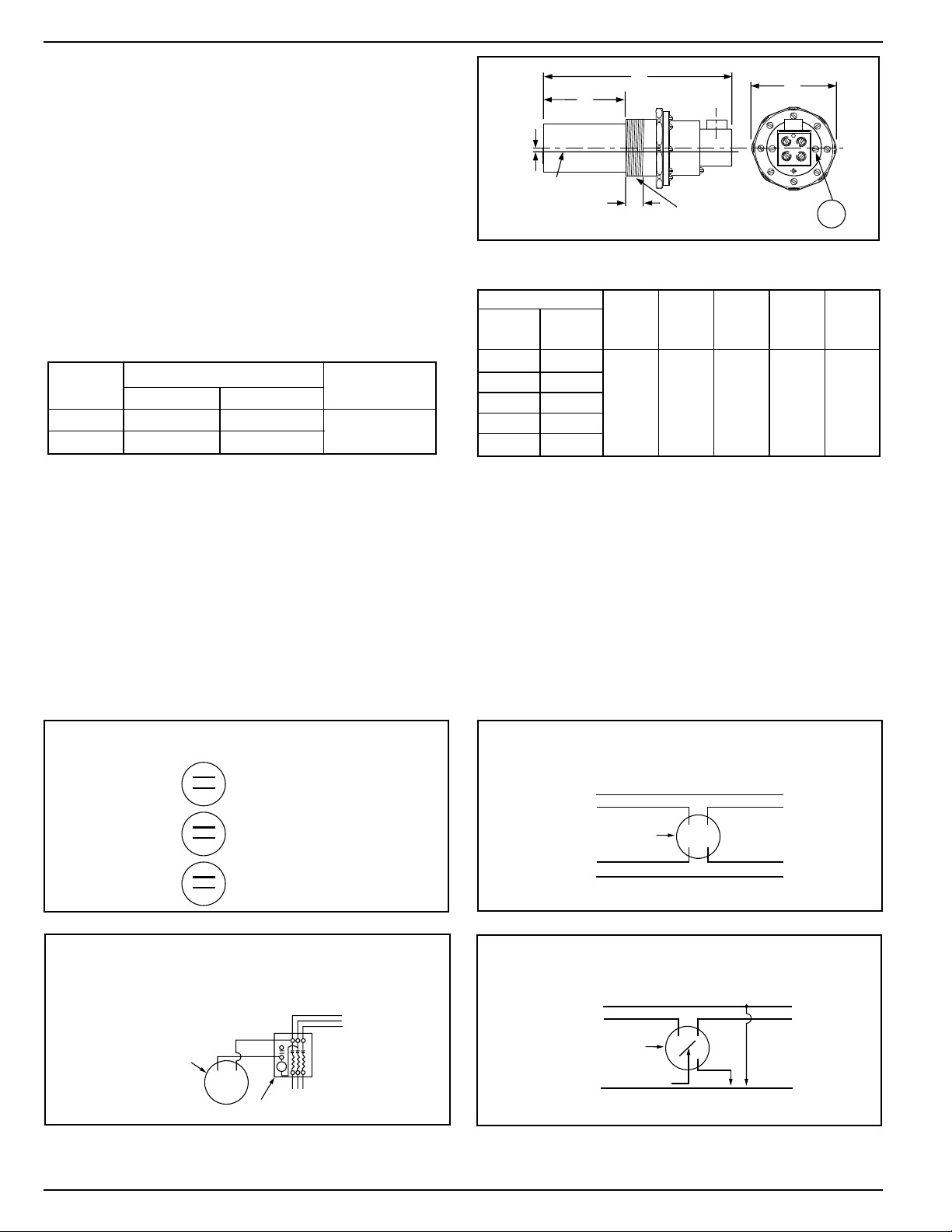
The 69 Series Built-in Low Water Cut-Off is furnished
with a threaded barrel casting which fits right into a
2 1/2" tapping provided by some boiler manufacturers
in the side of the boiler. Selection of the particular
model depends upon the insertion length into the
boiler (see chart). Order the built-in which provides
maximum insertion within the boiler.
0
2
0
4
1
0
3
0
0
2
0
4
1
0
3
0
0
2
0
4
1
0
3
0
SCHEMATIC OF TWIN SWITCH
INTERNAL OPERATION
NORMAL WATER LEVEL
FEEDER OR ALARM
OPERATING LEVEL
LOW WATER CUT-OFF
OPERATING LEVEL
NEUTRAL WIRE
NEUTRAL WIRE
HOT WIRE
HOT WIRE
TO BURNER
TO ALARM
SAFETY
SWITCH
0
2
0
4
1
0
3
0
USED AS MAIN LINE SWITCH
Diagram 1
Diagram 2
TO LINE
TO BURNER
STARTER
SAFETY
SWITCH
L1
L2
L3
0
2
0
4
1
0
3
0
USED AS PILOT SWITCH IN SERIES WITH
HOLDING COIL OF AUTOMATIC STARTER
NEUTRAL WIRE
TO
TWO WIRES OF 101A
OR TO ALARM CIRCUIT
HOT WIRE
TO BURNER
JUMPER
SAFETY
SWITCH
0
2
0
4
1
0
3
0
USED WITH MODEL 101 ELECTRIC
WATER VALVE OR IN ALARM CIRCUIT
Diagram 3 Diagram 4
IMPORTANT: Low water cut-off circuit of the 69 series must be electrically wired in series with all other boiler
limit operating controls.
Based on desired usage, connect wires from low water cut-off to appropriate control/alarm.
OPERATION
Maximum Steam Pressure: 20 psi (1.4 kg/cm2)
Electrical Ratings
Motor Switch Rating (Amperes)
Voltage Full Load Locked Rotor Pilot Duty
125 VA at
120 or 240 VAC
ABCDEF
Insertion
Model Length NPT
69 4
1
⁄8
(105)
169 3
1
⁄
8
(79)
269 2
1
⁄
4
(57) 1 (25) 4
1
⁄
8
(105)
1
⁄
8
(3) 2
1
⁄
2
9
1
⁄
2
(241)
369 1
3
⁄
4
(45)
469, 569 1
3
⁄
16
(30)
Dimensions, in. (mm)
NOTE: MV models are rated at 24 VA @ 24 VAC to 120 VAC
A
F
C
120 VAC
240 VAC
7.4 44.4
3.7
22.2
D
CUT-OFF
LEVEL
B
E
12
34
AA
Page 3
OFF
ON
• Turn the boiler off.
• Drain the water in the boiler to a level which is below the
tapping on the boiler. Allow the boiler to cool to 80˚F (27˚C)
and allow the pressure to release to 0 psi (0 bar).
• Determine where to install the control. The low water cut-off
must be positioned at or above the boiler manufacturer’s
minimum safe water level.
• Separate the mounting barrel from the control slightly by
loosening the eight (8) slotted screws on the clamping ring.
This allows the barrel to be turned into the tapping in the
boiler without rotating the whole control. (The barrel may
also be completely removed to install easily).
• Apply a small amount of pipe dope or thread sealant to the
2 1/2 NPT and hand screw the barrel into the boiler without
rotating the rest of the control. Tighten the barrel securely
using a pipe wrench to about 150 ft-lbs. (200 N•m) torque.
• Rotate the control in the barrel to the finished position using
a level to set the two (2) conduit housing screws (AA) in a
horizontal position. Complete the installation by securing the
control onto the barrel by tightening the eight (8) clamping
ring screws to 5 ft-lbs (7 N•m) torque. "TOP" on the switch
terminal panel MUST be in the up position.
INSTALLATION –
TOOLS NEEDED:
One (1) flathead screwdriver, one (1) level indicator
and one (1) pipe wrench.
3
Installation of the Low Water Cut-Off
The center line on the casting of the Series 69 must be installed above the lowest permissible water level
determined by the boiler manufacturer.
Whether the gauge glass is mounted directly into the boiler or on an independent water column, the cut-off line on
the 69 control should be mounted 1/2” (15mm) above the lowest visible point of the gauge glass.
IMPORTANT: Follow the boiler manufacturer's
instructions along with all applicable codes and
ordinances for piping, blow down valve and water
gauge glass requirements.
NOTE: To connect wires to the terminals on
the water feeder, burner, or low water cut-off,
place the bare end of the wire under the terminal screw and tighten the screw with a flathead
screwdriver.
Cover
Using a flathead screwdriver, remove the one (1)
screw that secures the switch cover.
minimum safe
water level
Cut-off
level
Clamping ring
and 8 screws
AA
Page 4

Wiring Instructions
• To prevent electrical shock, turn off the electrical power before making electrical connections.
• This low water cut-off must be installed in series with all other limit and operating controls installed on the
boiler. After installation, check for proper operation of all of the limit and operating controls before leaving
the site.
Failure to follow this warning could cause electrical shock, an explosion and/or a fire, which could result in
property damage, personal injury or death.
!
WARNING
TOP LEFT BOTTOM RIGHT
TOP12
34
Electrical connector is movable into any one of four positions illustrated, by simply removing two black headed screws and rotating
housing.
NOTE: This control should be wired with materials suitable for use
at 75˚C.
Switch Operation
The No. 11 switch can be identified by a black terminal panel. The
switch contains two (2) single pole single throw switches to control
the water feeder and the low water cut-off. The low water cut-off
switch is between terminals marked “1” and “2”. A second switch is
located between terminals marked “3” and “4”. This can be used to
operate a low water alarm or a McDonnell & Miller electric water
feeder.
Wiring Diagrams:
Series 69 Low Water Cutoff with M&M Model 101-A Electronic Water Feeders
120V Burner and 120V Feeder
BURNER
120 VAC
SUPPLY
12
34
N
H
101A
69
Using a wire nut, connect a wire from the neutral side of the power supply to one of the wires inside the feeder's junction box. (Does not make
a difference which one). Connect a wire from the "hot" side of the power
supply to terminal 2 of the Series 69 junction box. Connect the neutral
side of the power supply to the burner.
Connect the wire from the burner to terminal 1 of the low water cut-off.
Connect a "jumper" from terminal 2 to terminal 3 of the low water cut-off.
Connect a wire from terminal 4 of the low water cut-off to the remaining
wire in the 101-A water feeder.
24V Burner and 24V Feeder
BURNER
101A-24
120 VAC
SUPPLY
24V TRANSFORMER
(101-24V-48)
12
34
N
H
24V
69
Connect the "hot" wire from the boiler transformer to terminal 2 of the low
water cut-off. Connect the "hot" side of the water feeder transformer to
terminal 3 of the low water cut-off. Connect the neutral side of the boiler
transformer to the burner. Using a wire nut, connect the neutral side of the
water feeder transformer to the water feeder.
Connect the wire from the burner to terminal 1 of the low water cut-off.
Connect a wire from terminal 4 of the low water cut-off to the remaining
wire in the water feeder.
4
To prevent damage to the water feeder, a McDonnell
& Miller transformer Model 101-24V-48 must be used.
!
IMPORTANT
Page 5

BURNER
101A
120 VAC
SUPPLY
N
H
24V
12
34
69
Wiring Alternatives - Controls of Different Voltages
For 120V Burner/24V Feeder setups For 24V Burner/120V Feeder setups
BURNER
101A-24
120 VAC
SUPPLY
24V TRANSFORMER
(101-24V-48)
TO AVOID DAMAGE TO 101A
SOLENOID COIL, TRANSFORMER
101-24V-48 MUST BE USED.
N
H
12
34
69
Wire only terminals 1 and 2 into the millivolt circuit. Do not
attach any other wiring to terminals 1 and 2.
Install wire (A) from water feeder to 120 volt Neutral wire.
Install wire (B) from water feeder to terminal 4 of the low
water cut-off.
Install wire (C) from terminal 3 of the low water cut-off to 120
volt Hot wire.
MILLIVOLT
BURNER
CIRCUIT
12
34
101A
FEEDER
A
B
C
120 VAC
SUPPLY
HOT
NEUTRAL
WIRE
NUTS
Models 69-MV-P and 369-MV Millivolt Burner Circuit Controls with Water Feeder
Millivolt Burner Control and Model 101-A 120V Water Feeder
24V TRANSFORMER
(101-24V-48)
12
34
101A-24
A
C
D
B
E
120 VAC
SUPPLY
WIRE
NUTS
MILLIVOLT
BURNER
CIRCUIT
Wire only terminals 1 and 2 into the millivolt circuit.
Do not attach any other wiring to terminals 1 and 2.
Install wire (A) from 120 volt circuit Neutral wire
to the transformer input Neutral terminal.
Install wire (B) from burner circuit Hot wire to the
transformer input Hot terminal.
Install wire (C) from transformer output Neutral
terminal to the water feeder.
Install wire (D) from the water feeder to terminal 4
on the low water cut-off.
Install wire (E) from terminal 3 on the low water
cut-off to the transformer output Hot terminal.
Millivolt Burner Control and Model 101-A 24V Water Feeder
To prevent damage to the water feeder, a McDonnell
& Miller transformer Model 101-24V-48 must be used.
!
IMPORTANT
To prevent damage to the water feeder, a McDonnell
& Miller transformer Model 101-24V-48 must be used.
!
IMPORTANT
5
Page 6

24V Burner/120V Feeder
120V Burner/120V Feeder
or
24V Burner/24V Feeder
Connect a wire from the "Hot" side of the power supply to the
water feeder terminal 3, and low water cut-off terminal 2.
Connect a wire from the neutral side of the power supply to the
water feeder terminal 2, and to the neutral side of the burner.
Connect the wire from the burner to terminal 1 of the low water
cut-off. Connect a jumper from terminal 2 to terminal 3 of the
low water cut-off. Connect a wire from terminal 4 of the low
water cut-off to terminal 1 of the water feeder.
120V Burner/24V Feeder
Switch Initial Initial Dwell/Feed
Position Dwell Feed Cycles
M&M 60 60 Repeats until LWCO
seconds seconds reactivates the
burner circuit
2 90 90 One
seconds seconds
3 100 100 One
seconds seconds
Wiring Diagrams (continued):
Series 69 Low Water Cut-off with M&M Model WF-2-U Electronic Water Feeders
The Uni-Match®water feeders have a three-position
slide
switch which initiates a dwell period specific to the position of
the switch. If the system condensate raises the boiler water
level above the cut-off level during the dwell period, no additional water will be added to the boiler. Once the dwell period
has passed, the feeder will be activated and water will be
added to the boiler. The feeder will be deactivated when the
LWCO reactivates the burner circuit.
The position of the slide switch also sets the length of the
dwell period, the length of time valve is open and the number
of dwell/feed cycles. The control is set with the slide switch in
position 3 and can be changed in the field after installation.
The chart on the right indicates the cycles and length of
dwell/feed cycles for each position.
6
WIRING ALTERNATIVES
WHEN USING MIXED VOLTAGES
M&M
2
3
&M
M
2
3
BURNER
69
WF2-U-120 or
WF2-U-24
12
3 4
W
or
1
N
Supply Voltage
SAME as Feeder
H
N
H
or
or
2
3
24V
TRANSFORMER
BURNER
69
12
3 4
W
N
WF2-U-120
H
or
or
or
1
2
3
BURNER
69
12
3 4
W
N
WF2-U-24V
H
or
or
or
1
2
3
N
120 VAC
SUPPLY
H
N
120 VAC
H
SUPPLY
24V
TRANSFORMER
Page 7

TESTING
• Manually fill boiler until water level in the sight
glass is above the control.
• Turn on the power to the boiler and water feeder.
Activate the burner by raising the thermostat set
point.
• Using the sight glass as a reference, slowly
drain water from boiler by opening the blow
down valve or the boiler drain until the low water
cut-off activates the water feeder.
IMPORTANT: If the water feeder does not
activate before the water level reaches the
bottom of the sight glass, immediately close
any open drain or blow down valve and check
controls and piping for proper installation.
Correct any problems.
• Continue to drain the boiler slowly. If the burner
does not turn off before the water level reaches the
bottom of the sight glass, immediately close any
open drain or blow down valve. Check control for
proper installation. Correct any problems.
• Once the burner turns off on low water, close all
boiler drains or blow down valves.
• Using the sight glass as a reference, see that
the water feeder activates and fills to approximately 1/2” to 1” (13 - 25mm) above the
burner cut-off level of the low water cut-off.
IMPORTANT: If the water feeder does not
turn off once the water level has surpassed
the halfway point of the sight glass, immediately turn off the power to the boiler and water
feeder and check control for proper installation.
Correct any problems.
• Repeat test 2 or 3 times. Restore boiler and
controls to normal settings.
INSTALLATION COMPLETE
LWCO
Level
Cover
Switch
Housing
Replace the cover on the switch housing and,
using a flathead screwdriver, tighten the one (1)
screw to approximately 2 ft•lb (2.6 N•m).
7
Page 8

TROUBLESHOOTING
Problem:
1. Burner does not shut off on low water.
a. Cause: Float shield is loaded with mud or sedi-
ment. Shield may be out of position or
damaged; bellows folds obstructed.
Test: With water level below the control check if
terminals 1 and 2 are open. If not, remove
switch and manually test if terminals 1 and
2 can be opened.
Solution: Remove the control and clean. At this time,
check for a build-up of scale or sediment
between corrugations of the bellows.
b. Cause: Contacts are fused together.
Test: Remove switch and operate manually to ver-
ify proper switch operation.
Solution: Replace switch. Check electrical load and
make sure it is within the ratings of the
switch.
MAINTENANCE
SCHEDULE:
• Blow down weekly (at least once) when the
boiler is in operation.
• Disassemble and inspect annually. Replace
the low water cut-off if it is worn, corroded,
or if components no longer operate properly.
• Inspect the shield, float and bellows annually.
Remove all sediment and debris.
• We recommend replacement when the switch no
longer operates properly.
If you choose to replace the switch, order the
McDonnell & Miller replacement switch and follow the
Repair Procedure provided.
• Replace the low water cut-off every 10 years.
More frequent replacement may be required when
severe conditions exist such as rapid switch cycling,
surging water levels, and use of water treatment
chemicals.
2. Electric water feeder does not shut off.
a. Cause: Float obstructed or damaged. Build-up of
scale or sediment between corrugations of
the bellows. Shield may be out of position.
Test: With water level above the control, check if
terminals 3 and 4 are open. If not, remove
switch and manually test to verify terminals 3 and 4 can be opened.
Solution: Check the clearance of the shield; replace
or clean the bellows.
b. Cause: Contacts are fused together.
Test: Remove switch and operate manually to
verify proper switch operation.
Solution: Replace switch. Check electrical load and
make sure it is within the ratings of the
switch.
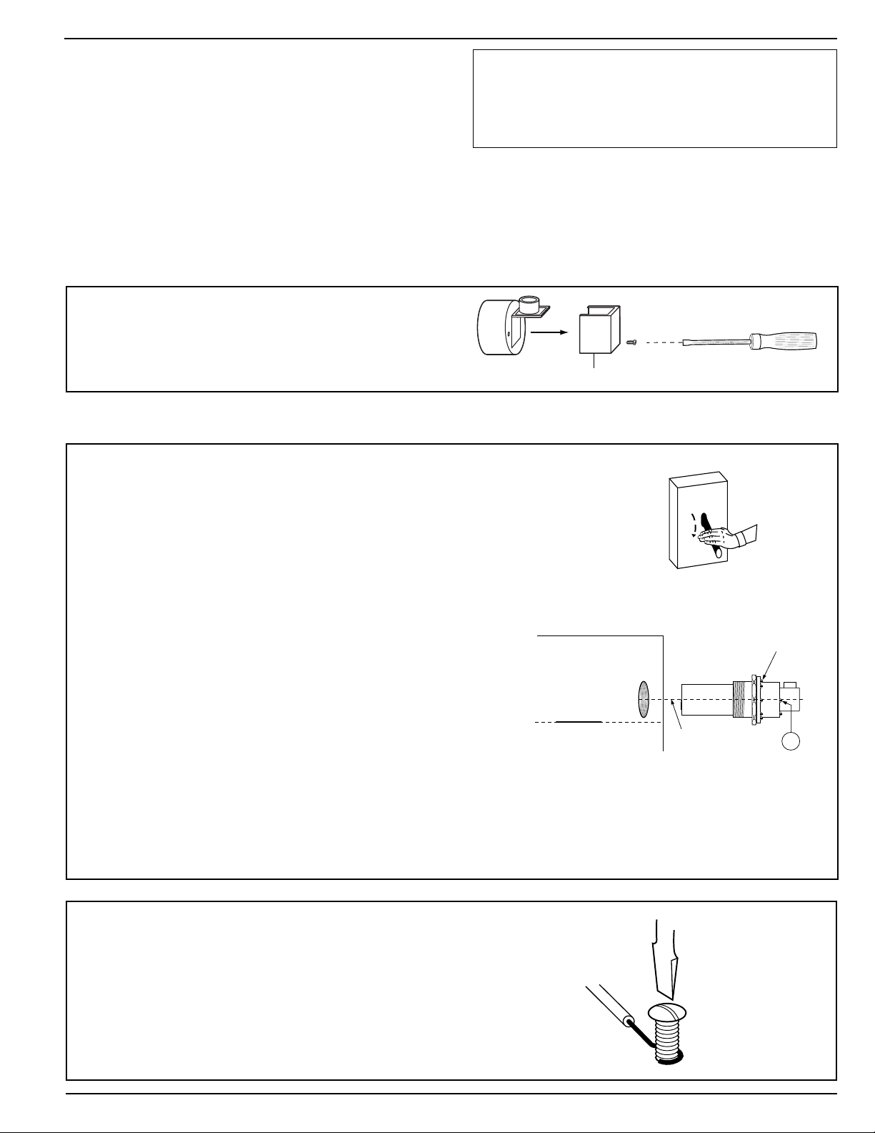
PROCEDURE:
CAUTION
!
To prevent serious personal injury from steam pipe
blow down, connect a drain pipe to avoid exposure to
steam discharge.
Failure to follow this caution could cause personal
injury.
Test the low water cut-off when the water level is at its
normal level and the burner is on. Slowly open the
boiler drain valve and observe the water level fall in
the gauge glass. Close the valve after verifying that
the alarm/feeder contacts have closed and the burner
shuts off. If this does not happen, immediately shut off
the boiler and correct the problem.
Xylem Inc.
8200 N. Austin Avenue
Morton Grove, Illinois 60053
Phone: (847) 966-3700
Fax: (847) 965-8379
www.xyleminc.com/brands/mcdonnellmiller
McDonnell & Miller is a trademark of Xylem Inc. or one of its subsidiaries.
© 2013 Xylem Inc. MM-226C July 2013 Part No. 246753
 Loading...