

Page 1
INSTRUCTION MANUAL
IM213R04
™
Aquavar SPD
Variable Speed Pump Control
INSTALLATION, OPERATION AND MAINTENANCE INSTRUCTIONS
Page 2

INDEX
Important Safety Instructions ...........................................................................................................................3
System Components ......................................................................................................................................... 4
System Design ...................................................................................................................................................5
Piping .................................................................................................................................................................. 7
Mounting the Controller ................................................................................................................................... 8
Power Supply and Wiring ................................................................................................................................. 9
Starting the System (Input/Output Connections, Switch Settings, Motor Rotation) ................................14
Input and Output Functions (Control Terminals) ......................................................................................... 19
Troubleshooting ..............................................................................................................................................20
Controller Dimensions ....................................................................................................................................25
Appendix (Input Wire Sizing Chart) ...............................................................................................................26
Appendix (Output Wire Sizing Chart) ...........................................................................................................27
Limited Warranty ..............................................................................................................................................28
NOTE:
• Use Copper wire only.
• Suitable for use in a pollution degree 2 micro-environment.
• Motor overload protection provided at 100% of full load current.
• In order to maintain the environmental rating integrity of the enclosure, all openings must be closed
by equipment rated 3, 3R, 3S, 4, 4X, 6 or 6P.
• Maximum Ambient temperature range -22º F to 122º F.
• Maximum Humidity: 95% at 104º F non-condensing.
• Controller is rated TYPE 3R (Raintight) so it may be located outdoors
Page 2
Page 3
DANGER
Hazardous
voltage
DANGER
Hazardous
Pressure
CAUTION
SAFETY INSTRUCTIONS
WARNING
CAUTION
CAUTION
Section 1
Important: Read all safety information prior to installation of the Controller.
NOTE
This is a SAFETY ALERT SYMBOL. When you see this symbol on the controller, pump or in this
manual, look for one of the following signal words and be alert to the potential for personal
injury or property damage. Obey all messages that follow this symbol to avoid injury or death.
Indicates an imminently hazardous situation which, if not avoided, will result in death or
serious injury.
Indicates a potentially hazardous situation which, if not avoided, could result in death or
serious injury.
Indicates a potentially hazardous situation which, if not avoided, may result in minor or
moderate injury.
Used without a safety alert symbol indicates a potentially hazardous situation which, if
not avoided, could result in property damage.
NOTE Indicates special instructions which are very important and must be followed.
NOTE
All operating instructions must be read, understood, and followed by the operating personnel. CentriPro
accepts no liability for damages or operating disorders which are the result of non-compliance with the
operating instructions.
1. This manual is intended to assist in the installation, operation and repair of the system and must be kept with
the system.
2. Installation and maintenance MUST be performed by properly trained and qualied personnel.
3. Review all instructions and warnings prior to performing any work on the system.
4. Any safety decals MUST be left on the controller and/or pump system.
5. The system MUST be disconnected from the main power supply before attempting any operation
or maintenance on the electrical or mechanical part of the system. Failure to disconnect electrical
power before attempting any operation or maintenance can result in electrical shock, burns or
death.
6. When in operation, the motor and pump could start unexpectedly and cause serious injury.
Page 3
Page 4

WARNING
Hazardous
voltage
Hazardous
Pressure
CAUTION
SYSTEM COMPONENTS
Section 2
Please review the SPD components and insure that you have all the parts and are familiar with their names. Be
sure to inspect all components CentriPro supplies for shipping damage.
SPD Variable Speed Controller:
1. SPD Controller
2. Pressure Transducer with Cable
3. Conduit Plate Caps
WARNING
DO NOT power the unit or run the pump until all electrical and plumbing connections,
especially the pressure sensor connection, are completed. The pump should not be run dry.
All electrical work must be performed by a qualied technician. Always follow the National
Electrical Code (NEC), or the Canadian Electrical Code (CEC) as well as all local, state and
provincial codes. Code questions should be directed to your local electrical inspector or code
enforcement agency. Failure to follow electrical codes and OSHA safety standards
may result in personal injury or equipment damage. Failure to follow manufacturer's installation instructions
may result in electrical shock, re hazard, personal injury, death, damage to equipment, unsatisfactory
performance and may void manufacturer's warranty.
Controller Product Code Information
SPD Y XXXX F
F = with Output Filter for Submersible Pump Applications
BLANK = without Filter for Above Ground/Centrifugal Pump Applications.
4 Digits for HP
5 HP = 0050
7.5 HP = 0075
10 HP = 0100
15 HP = 0150
20 HP = 0200
25 HP = 0250
30 HP = 0300
1 Digit for Input Voltage
230 volt = 2
460 volt = 4
575 volt = 5
SERIES
Page 4
Page 5
SYSTEM DESIGN
Section 3
NOTE
Systems MUST be designed by qualied technicians only and meet all applicable state and local code
requirements.
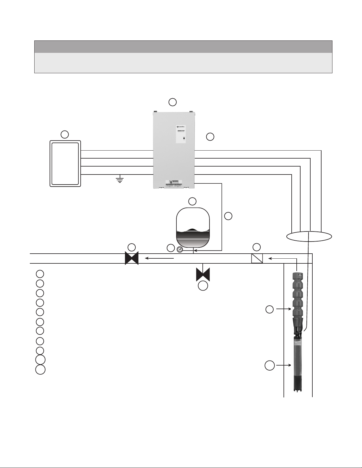
The following diagrams show a typical system using the SPD_ _ F with Filter, Constant Pressure Controller.
Diagram #1 shows a typical set up for a submersible system.
1
2
SUPPLY POWER
L1
L2
L3
GND
6
T1
T2
T3
GND
4
5
8
3
FLOW
7
1 SPD_F CONTROLLER
2 FUSIBLE DISCONNECT
11
3 PRESSURE GAUGE
4 AIR DIAPHRAGM TANK
5 PRESSURE TRANSDUCER
6 3 PHASE OUTPUT (ALWAYS)
7 DISCHARGE CHECK VALVE
8 GATE VALVE (HIGHLY RECOMMENDED)
9 SUBMERSIBLE PUMP END
10 SUBMERSIBLE MOTOR (3 PHASE)
11 PRESSURE RELIEF VALVE
NOTE: FOR SINGLE PHASE INPUT, CONNECT L1 AND L3, THEN SET MOTOR
OVERLOAD SWITCHES TO 50% OF CONTROLLER RATING OR LOWER.
9
10
Page 5
Page 6
SYSTEM DESIGN
Section 3 (continued)
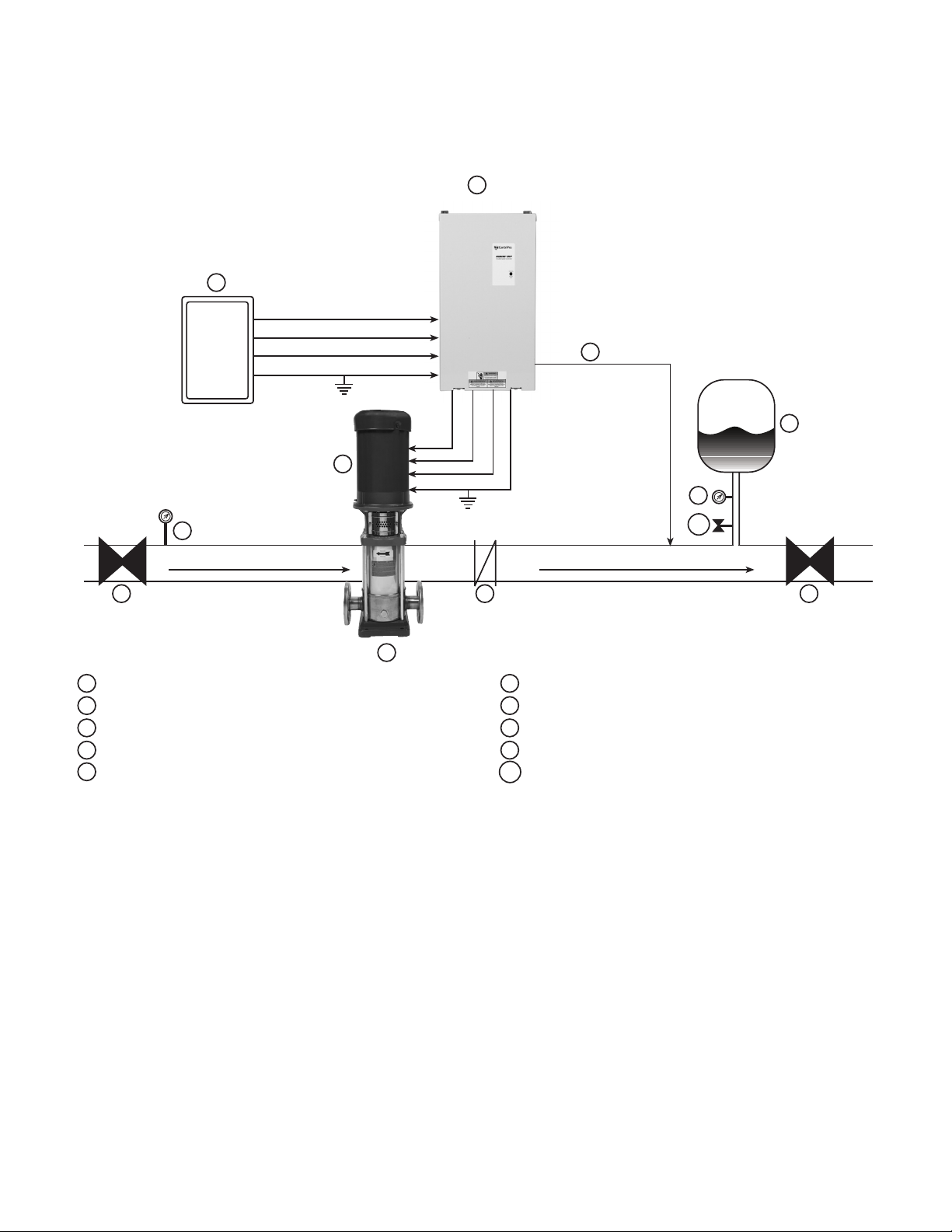
Diagram #2 shows a set-up for municipal water connection.
1
2
9
SUCTION
8
SUPPLY POWER
L1
L2
L3
GND
7
T1
T2
T3
3 PHASE OUTPUT
GND
TO MOTOR
4
5
9
10
FLOW
3
1 SPD CONTROLLER 6 AIR DIAPHRAGM TANK
2 FUSIBLE DISCONNECT 7 3 PHASE MOTOR
3 CENTRIFUGAL PUMP 8 GATE VALVE (BALL VALVE)
4 CHECK VALVE 9 PRESSURE GAUGE
5 PRESSURE TRANSDUCER (CABLE ASSEMBLY) 10 PRESSURE RELIEF VALVE
AIR
6
8
NOTES: For single phase input power, use L1 and L3 terminals and adjust motor overload switches
to 50% of controller rating or lower.
Page 6
Page 7
Hazardous
Pressure
CAUTION
Hazardous
Pressure
CAUTION
PIPING
Section 4
General
NOTE
All plumbing work must be performed by a qualied technician. Always follow all local, state and provincial
codes.
A proper installation requires a pressure relief valve, a ¼" female N.P.T. threaded tting for the pressure sensor,
and properly sized pipe. Piping should be no smaller than the pump discharge and/or suction connections.
Piping should be kept as short as possible. Avoid the use of unnecessary ttings to minimize friction losses.
Some pump and motor combinations supplied with this system can create dangerous pressure.
Select pipe and ttings accordingly per your pipe suppliers’ recommendation. Consult local codes
for piping requirements in your area.
All joints must be airtight. Use Teon tape or another type of pipe sealant to seal threaded connections. Please
be careful when using thread sealant as any excess that gets inside the pipe may plug the pressure sensor.
Galvanized ttings or pipe should never be connected directly to the stainless steel discharge head or casing as
galvanic corrosion may occur. Barb type connectors should always be double clamped.
Pressure Tank, Pressure Relief Valve and Discharge Piping
Use only “pre-charged” tanks on this system. Do not use galvanized tanks. Select an area that is always above
34º F (1.1º C) in which to install the tank, pressure sensor and pressure relief valve. If this is an area where a water
leak or pressure relief valve blow-off may damage property, connect a drain line to the pressure relief valve. Run
the drain line from the pressure relief valve to a suitable drain or to an area where water will not damage
property.
Pressure Tank, System Pressure
Sizing – A diaphragm tank (not included) is used to cushion the pressure system during start-up and shut-down.
It should be sized to at least 20% of the total capacity of your pump. Example: If your pump is sized for 100 GPM
then size your tank for at least 20 gal. total volume, not draw down. Pre-charge your bladder tank to 10-15 PSI
below your system pressure. The controller is pre-set for 50 PSI at the factory. Therefore a 35-40 PSI pre-charge in
your tank would be required. Use the higher tank pre-charge setting if the system drifts over 5 PSI at a constant
ow rate. NOTE: Pre-charge your tank before lling with water!
CAUTION
Maximum working pressure of HydroPro diaphragm tank is 125 psi.
Installing the Pressure Sensor
The pressure sensor requires a ¼" FNPT tting for installation. Install the pressure sensor with the electrical
connector pointing up to avoid clogging the pressure port with debris. Install the pressure sensor in a straight
run of pipe away from elbows or turbulence. For optimum pressure control install the pressure sensor in the
same straight run of pipe as the pressure tank. Ensure the pressure sensor is within 10ft of the pressure tank.
Installing the pressure sensor far away from the pressure tank may result in pressure oscillations. Do not install
the pressure sensor in a location where freezing can occur. A frozen pipe can cause damage to the pressure
sensor.
Page 7
Page 8

WARNING
Hazardous
voltage
PIPING
Section 4 (continued)
The pressure sensor cable is prewired to the controller. The cable can be shortened for a cleaner installation.
Longer cable lengths are available, consult factory. Maximum recommended pressure sensor cable length is
300ft. Avoid leaving a coil of pressure sensor cable as this can induce unwanted transient voltages and noise into
the system. Do not run the pressure sensor cable alongside the input or output wiring. Maintain a distance of at
least 8” between the pressure sensor cable and input or output wiring.
Ensure the pressure sensor cable is connected as follows: Brown to terminal 7 (24VDC SUPPLY), White to
terminal 6 (TRANSDUCER INPUT), Drain to chassis. Connecting the Drain wire to the chassis electrically
connects the sensor case to the chassis of the controller. In some cases this drain wire must be disconnected
from the controller chassis. In cases where the there is grounded metal piping which is continuous between the
transducer and the motor or the transducer is installed in grounded metal piping, a ground loop can result so
the drain wire must be disconnected from the chassis. In cases where there are sections of nonmetallic piping
between the transducer and motor or the transducer is installed in ungrounded piping this drain wire should be
connected to the controller chassis.
MOUNTING THE CONTROLLER
Section 5
General
Mount the controller in a well ventilated, shaded area using 4 screws. The controller must be mounted vertically.
Be sure to leave 8 inches of free air space on every side of the unit. The controller must be in an area with an
ambient between -22º F and 122º F. If installation is above 3300 feet above sea level, ambient temperatures
are derated 1% per 330 feet above 3300 feet. The altitude limit for this controller is 6500 ft. Do not install above
6500 ft.
NOTE
Do not block the heat sink (ns) or fans and do not set anything on the units.
WARNING
The controller access cover should always be securely fastened to the control box due to the
dangerous voltage/shock hazard inside the unit. A lock can be used to prevent unwanted entry.
Page 8
Page 9
WARNING
Hazardous
voltage
POWER SUPPLY AND WIRING
Section 6
Power Supply
NOTE
Installation and maintenance MUST be performed by properly trained and qualied personnel. Always follow
the National Electrical Code (NEC) or Canadian Electric Code (CEC), as well as all state, local and provincial
codes when wiring the system.
The type of transformer and the connection conguration feeding a drive plays an important role in its
performance and safety. The following is a brief description of some of the more common congurations and a
discussion of their virtues and shortcomings. Always ask what type of power system the site has before sizing the
drive.
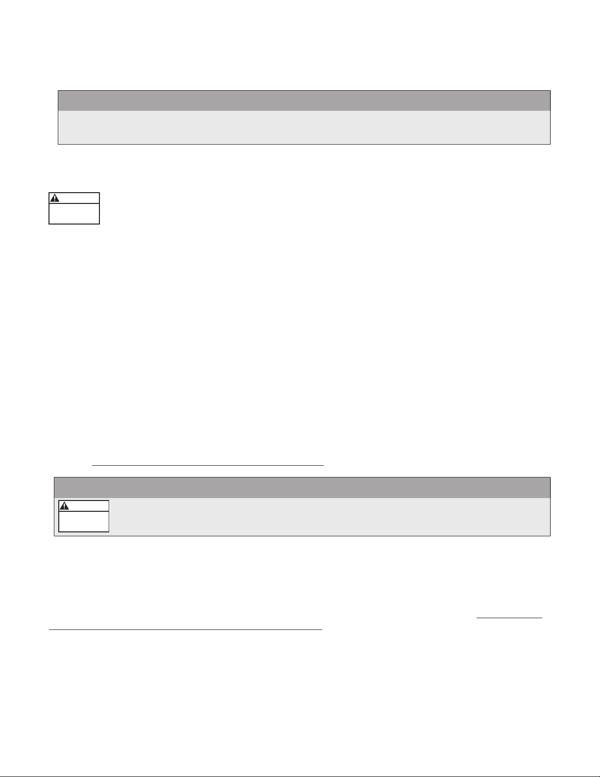
Delta/Wye with grounded Wye neutral
This conguration is one of if not the most common. It provides rebalancing of unbalanced voltage with a 30
degree phase shift. Depending on the output connections from the drive to motor, the grounded neutral may be
a path for common mode current caused by the drive output.
Delta/Delta with grounded leg
Another common conguration providing voltage rebalancing with no phase shift between input and output.
Again, depending on the output connections from the drive to motor, the grounded neutral may be a path for
common mode current caused by the drive output.
In this case the line to ground voltage on the phases that are not grounded will be equal to the phase to phase
voltage. This voltage can exceed the voltage ratings of the EMC lter and input MOV protection devices. This can
cause catastrophic controller failure if the line to ground EMC lter and input MOV protection devices are not
disconnected. Refer to Disconnecting EMC Filter and MOVs for details on line to ground voltage limitations and
disconnecting these devices.
WARNING
If the secondary of the transformer is a delta with a grounded leg (corner grounded delta), the
line to ground EMC lter components and line to ground MOV protection must be disconnected
or damage to the controller can result.
Page 9
Page 10

WARNING
Hazardous
voltage
POWER SUPPLY AND WIRING
Section 6 (continued)
Ungrounded secondary
Grounding of the transformer secondary is essential to the safety of personnel as well as the safe operation of
the drive. Leaving the secondary oating can permit dangerously high voltages between the chassis of the drive
and the internal power structure components. In many cases this voltage could exceed the rating of the EMC
lter and input MOV protection devices of the drive causing a catastrophic failure. In all cases, the input power to
the drive should be referenced to ground. If the transformer can not be grounded, then an isolation transformer
must be installed with the secondary of the transformer grounded.
In this conguration the line to ground voltage from the incoming power supply may exceed the voltage rating
of the line to ground EMC lter components and line to ground MOV protection. This can cause catastrophic
controller failure if the line to ground EMC lter and input MOV protection devices are not disconnected. Refer
to Disconnecting EMC Filter and MOVs for details on line to ground voltage limitations and disconnecting these
devices.
WARNING
If a power system with an ungrounded secondary is used, the line to ground EMC lter
components and line to ground MOV protection must be disconnected or damage to the
controller can result.
Resistance grounding and ground fault protection
Connecting the Wye secondary neutral to ground through a resistor is an acceptable method of grounding.
Under a short circuit secondary condition, any of the output phases to ground will not exceed the normal
line to line voltage. This is within the rating of the MOV input protection devices on the drive. The resistor is
often used to detect ground current by monitoring the associated voltage drop. Since high frequency ground
current can ow through this resistor, care should be taken to properly connect the drive motor leads using
the recommended cables and methods. In some cases, multiple drives on one transformer can produce a
cumulative ground current that can trigger the ground fault interrupt circuit.
Page 10
Page 11
WARNING
Hazardous
voltage
POWER SUPPLY AND WIRING
Section 6 (continued)
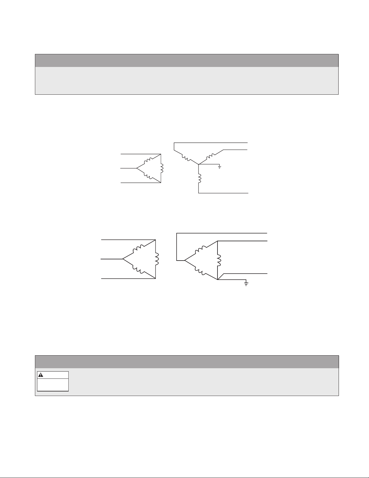
Open Delta (consult factory)
This type of conguration is common on 230 volt systems. From time to time it may be encountered where
only single phase power is available and three-phase power is required. The technique uses two single phase
transformers to derive a third phase. When used to power a drive this conguration must be derated to about
70% of the single phase rating of one transformer. This system provides poor regulation and it is possible that
only the two line connected phases will provide power. In this case the drive must be derated to 50 % of its
rating. (Ex. A 20 HP 230 volt drive now becomes a 10 HP 230 volt drive.)
WARNING
“Open Delta” power systems should be sized using the 50% derate factor. Consult factory.
Disconnecting EMC Filter and MOVs
For all controllers, if the line to ground voltage from the incoming power supply is greater than 300Vac then the
line to ground EMC lter components must be disconnected as described below. For 230V controllers, if the
line to ground voltage from the incoming power supply exceeds 300Vac then the line to ground MOVs must be
disconnected as described below. For 460V controllers, if the line to ground voltage from the incoming power
supply exceeds 550Vac then the line to ground MOVs must be disconnected as described below.
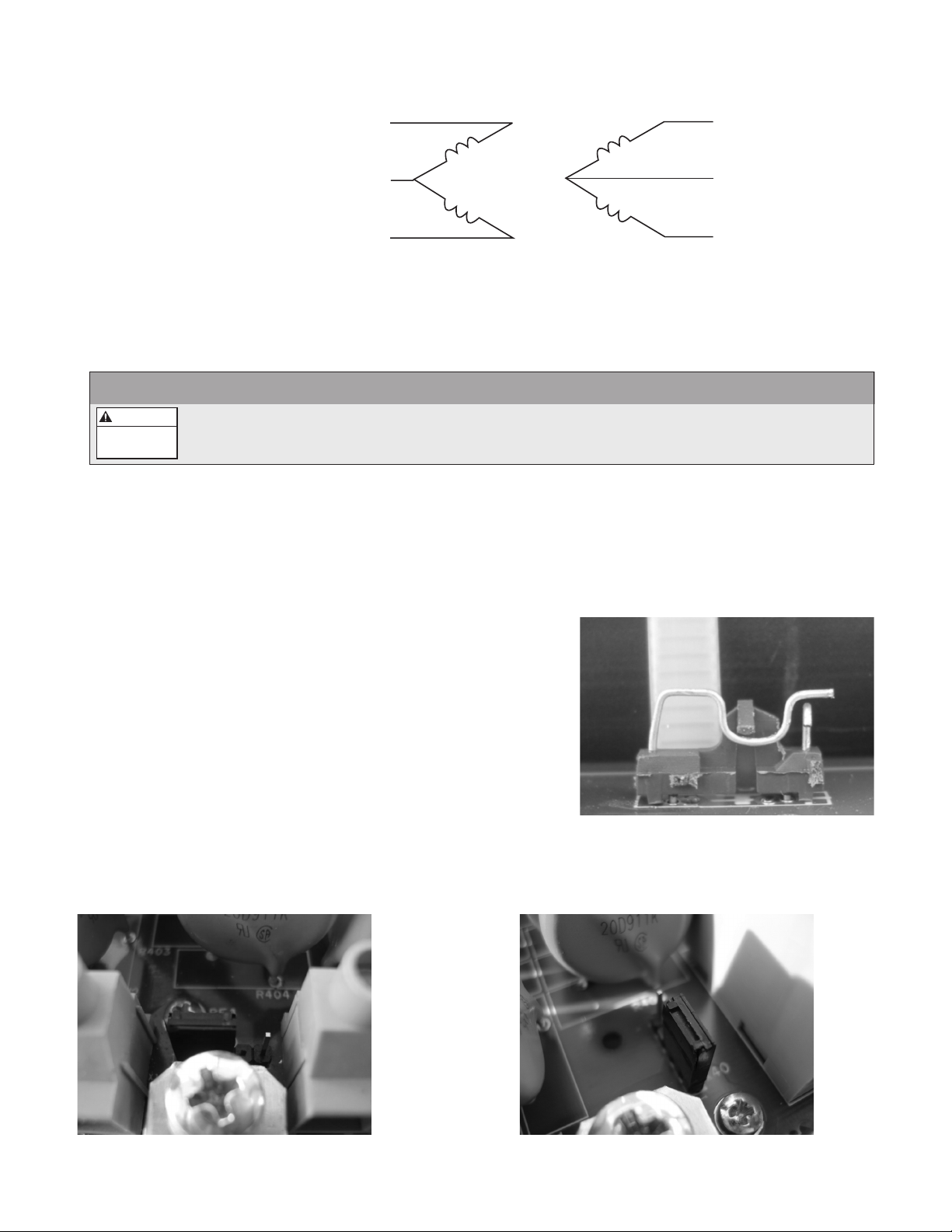
To disconnect the line to ground EMC lter components, locate
the jumper shown below. The jumper is on the left hand side of the
controller on the main board. Move to the disconnected position
shown to the right.
To disconnect the line to ground MOV protection, locate the jumper shown below. The jumper is located
between the input and output terminal blocks on the main board. Move to the position shown.
For Frame Size 1 Controllers: For Frame Sizes 2 and 3 Controllers:
Page 11
Page 12

POWER SUPPLY AND WIRING
Section 6 (continued)
For Frame Size 4 Controllers:
Single Phase Connection
For small drives with diode rectier front end it is possible to run a three phase output with a single phase input.
Only part of the three phase input bridge is used. Ripple current becomes 120 Hz rather than 360. This places a
greater demand on the DC lter components (capacitor bank and DC choke). The result is that the drive must be
derated to 50% current.
The chart below shows the full load output current ratings of the controller when single phase or 3 phase power
is used. If single phase input power is used the Motor Overload switches must be set to 50% or lower.
Supply
Voltage
208/230
460
Frame Size Model Number
1
2
3
4
1
2
3
SPD20050
SPD20050F
SPD20075
SPD20075F
SPD20100
SPD20100F
SPD20150
SPD20150F
SPD20200
SPD20200F
SPD20250
SPD20250F
SPD20300
SPD20300F
SPD40050
SPD40050F
SPD40075
SPD40075F
SPD40100
SPD40100F
SPD40150
SPD40150F
SPD40200
SPD40200F
SPD40250
SPD40250F
SPD40300
SPD40300F
Nominal HP Rating
Controller Full Load
Output Current Rating
3 Phase Input 1 Phase Input 3 Phase Input 1 Phase Input
5.0 2.0 17.8 8.1
7.5 3.0 26.4 10.9
10.0 5.0 37.0 17.8
15.0 7.5 47.4 26.4
20.0 10.0 60.6 33.0
25.0 12.0 76.0 40.2
30.0 15.0 94.0 47.4
5.0 8.9
7.5 13.2
10.0 18.5
15.0 23.7
20.0 30.3
25.0 37.5
30.0 47.0
Page 12
Page 13

POWER SUPPLY AND WIRING
Conduit, Wire and Fuse Sizing
The use of metal conduit with metal conduit connectors is recommended for all electrical connections. Use the
NEC or CEC to determine the required conduit size for the application.
Refer to the chart below for the minimum allowable wire size for each controller. Note that these wire sizes
are not adjusted for voltage drop due to long cable lengths. Refer to the wire sizing chart in the appendix to
determine the maximum length for the input cable. Refer to the motor manual for maximum output cable length.
The maximum recommended voltage drop on both input and output cable combined is 5%. Standard wire
sizing charts give maximum cable lengths for only input or output cables. Because of this the lengths given in the
table must be adjusted so the total voltage drop does not exceed 5%. For example, if the input wire sizing chart
in the appendix gives the maximum length of 400' and only 100' is used then only 25% of the total voltage drop
(1.25% drop) is used. The maximum output cable length read from the motor‘s wire sizing chart must then be
adjusted to 75% of its value so that the maximum voltage drop of 5% is not exceeded.
Use only fast acting class T fuses. The wire used for the input power connections on models SPD20300 and
SPD20300F must have a temperature rating of 90ºC minimum. All other wire must be rated 75 ºC minimum. The
chart below shows the recommended sizes for wire and fuses for each controller. Note that the wire sizes were
not adjusted for voltage drop due to long cable lengths.
Voltage Frame Size Model Number
SPD20050
SPD20050F
SPD20075
SPD20075F
SPD20100
SPD20100F
SPD20150
SPD20150F
SPD20200
SPD20200F
SPD20250
SPD20250F
SPD20300
SPD20300F
SPD40050
SPD40050F
SPD40075
SPD40075F
SPD40100
SPD40100F
SPD40150
SPD40150F
SPD40200
SPD40200F
SPD40250
SPD40250F
SPD40300
SPD40300F
208/230
460
1
2
3
4
1
2
3
Full Load
Output Current
17.8 5.0 30.0 7700
26.4 7.5 40.0 11400
37.0 10.0 50.0 16000
47.4 15.0 70.0 20500
60.6 20.0 80.0 26200
76.0 25.0 110.0 32800
94.0 30.0 135.0 40600
8.9 5.0 15.0 7700
13.2 7.5 20.0 11400
18.5 10.0 30.0 16000
23.7 15.0 40.0 20500
30.3 20.0 50.0 26200
37.5 25.0 60.0 32400
47.0 30.0 70.0 40600
Nominal HP Fuse Size
Generator
Size (VA)
Page 13
Page 14

WARNING
Hazardous
voltage
Hazardous
voltage
DANGER
POWER SUPPLY AND WIRING
Section 6 (continued)
Input Power and Line Transformer Requirements
The line input voltage and transformer power must meet certain phase and balance requirements. If you or
your installing electrical contractor is in doubt of the requirements, the following provide guidelines for
installation. When in doubt contact the local power utility or the factory.
Before connecting power to the controller measure the line to line and line to ground voltage from the power
source. The line to line voltage must be in the range of 195Vac to 265Vac (230V +/– 15%) for 230V models
and 391Vac to 529Vac (460V +/– 15%) for 460V models. The maximum phase to phase imbalance is +/– 3%.
If the phase to phase imbalance is greater than +/– 3% then an isolation transformer may be necessary. The
line to ground voltage must be less than 110% of the nominal (230V or 460V) line to line voltage. If the line to
ground voltage is not in this range the EMC lter and MOV components may need to be removed (see section
on “Ungrounded secondary” transformers) or an isolation transformer with a grounded secondary may be
necessary.
If an isolation transformer is used, the best choice is ONE three phase, six winding transformer. A delta primary
is best for third harmonic cancellation. A wye secondary avoids circulating current problems and provides the
very desirable option of grounding the secondary neutral for minimum voltage stress and ripple to ground. The
transformer should have a KVA rating at least 1.1 times the maximum connected HP. A K factor of 6 is sufcient if
transformer impedence is greater than 2%. A K Factor of 5 is sufcient if transformer impedence is greater than
3%. The transformer manufacturer may provide derating for non K Factor rated transformers to operate at the
drive produced K Factor levels.
Other transformer congurations are acceptable. Three single phase transformers can be used if they are
identical for phase to phase symmetry and balance. A wye connected primary neutral should never be
grounded. Great care should be taken with delta primary delta secondary congurations. Any lack of phase to
phase symmetry could result in circulating currents and unacceptable transformer heating.
WARNING
Never use phase converters with drives as nuisance tripping and possible damage may occur.
Instead, use single phase input power and 50% derate factor.
STARTING THE SYSTEM
Section 7
Output Power Connections
Run the motor lead wire from the motor or conduit box through metal conduit to the bottom of the
controller. Use metal conduit and metal conduit connectors. Size the conduits according to the NEC,
CEC or local codes. Connect conduit and insert the wires through the second or third opening from
the left. Choose the opening that ts or is larger than the conduit used. If the opening is larger than
the conduit, use conduit bushings to attach the conduit to the controller.
Consult motor manual to determine the wire size for the application. Ensure the ground connection to the motor
is continuous. Connect wires to the output terminal block labeled T1/U, T2/V, T3/W, and GND/ . Connect the
ground wire to the terminal labeled GND/ . Connect the other phase leads to T1/U, T2/V and T3/W.
For CentriPro Motors, connecting T1/U to Red, T2/V to Black and T3/W to Yellow will give the correct rotation.
Page 14
Page 15

Hazardous
voltage
DANGER
Hazardous
voltage
DANGER
Hazardous
voltage
DANGER
Hazardous
voltage
DANGER
Hazardous
voltage
DANGER
STARTING THE SYSTEM
Section 7 (continued)
DANGER
The controller has high leakage current to ground. The output terminals marked “GND” or
“ ” must be directly connected to the motor ground. Failure to properly ground the controller
or motor will create an electrical shock hazard.
Input Power Connections
Make sure disconnect switches or circuit breakers are securely in the OFF position before making
this connection. Run the input power wires from the fused disconnect through metal conduit to
the bottom of the controller. Use metal conduit and metal conduit connectors. Size the conduits
according to the NEC, CEC or local codes. Use the wire sizing chart in the appendix to determine
the size of the input power wires. Connect the conduit and insert the wires into the far left opening on the
controller. Connect wires to the “INPUT” terminal block. Connect the ground wire to the terminal labeled GND.
For three phase input, connect the input phase wires to L1, L2 and L3. For single phase input, connect the input
wires to L1 and L3. If single phase input is used the motor overload switches must be set to 50% or lower.
CAUTION
The wire used for input power connections on models SPD20300 and SPD20300F must have a temperature
rating of 90ºC minimum.
DANGER
The controller has a high leakage current to ground. The input terminals marked “GND” must be
directly connected to the service entrance ground. Failure to properly ground the controller or
motor will create an electrical shock hazard.
NOTE
If single phase input power is used the Motor Overload switches must be set to 50% or lower or nuisance
input phase loss errors can result.
NOTE
Do not use GFCI protection with this controller. Nuisance tripping will result.
DANGER
Status Code Indicator Light is not a voltage indicator! Always turn off disconnect switch and
circuit breaker and wait 5 minutes before servicing.
DANGER
The controller will remain electrically charged for 5 minutes after power is turned off. Wait 5
minutes after disconnecting power before opening controller access cover as there is a severe
shock hazard.
Page 15
Page 16

STARTING THE SYSTEM
Section 7 (continued)
Setting the Motor Overload Switches
The Motor Overload Setting Switches adjust the level of motor overload current
protection necessary to protect the motor in case of an over current condition.
Bank 1 switches 1, 2 and 3 allow adjustment of the motor overload setting. These
switches adjust the motor overload protection as a percentage of the full load
output current rating of the controller. Choose a motor overload setting that meets
or is less than the motor’s SFA rating. For example, if the full load output current
rating of the controller is 37A and the motor SFA rating is 33A, the motor overload
setting should be set to 85% (33A/37A = 89%, next lowest setting is 85%).
In applications where the pump and motor are not used to the full capacity the
system may not draw current close to the motor’s SFA rating. In this case choose a
motor overload setting that is close to the actual full load running current.
NOTE
If single phase input power is used the motor overload switches must be set to
50% or lower or nuisance input phase loss errors can result.
The chart below shows the motor overload setting for each model.
Supply
Voltage
208/230
460
Frame
Size
1
2
3
4
1
2
3
Model
Number
SPD20050
SPD20050F
SPD20075
SPD20075F
SPD20100
SPD20100F
SPD20150
SPD20150F
SPD20200
SPD20200F
SPD20250
SPD20250F
SPD20300
SPD20300F
SPD40050
SPD40050F
SPD40075
SPD40075F
SPD40100
SPD40100F
SPD40150
SPD40150F
SPD40200
SPD40200F
SPD40250
SPD40250F
SPD40300
SPD40300F
100% 95% 90% 85% 80% 70% 50% 40%
17.8 16.9 16.0 15.1 14.2 12.5 8.9 7.1
26.4 25.1 23.8 22.4 21.1 18.5 13.2 10.6
37.0 35.2 33.3 31.5 29.6 25.9 18.5 14.8
47.4 45.0 42.7 40.3 37.9 33.2 23.7 19.0
60.6 57.6 54.5 51.5 48.5 42.4 30.3 24.2
76.0 72.2 68.4 64.6 60.8 53.2 38.0 30.4
94.0 89.3 84.6 79.9 75.2 65.8 47.0 37.6
8.9 8.5 8.0 7.6 7.1 6.2 4.5 3.6
13.2 12.5 11.9 11.2 10.6 9.2 6.6 5.3
18.5 17.6 16.7 15.7 14.8 13.0 9.3 7.4
23.7 22.5 21.3 20.1 19.0 16.6 11.9 9.5
30.3 28.8 27.3 25.8 24.2 21.2 15.2 12.1
37.5 35.6 33.8 31.9 30.0 26.3 18.8 15.0
47.0 44.7 42.3 40.0 37.6 32.9 23.5 18.8
Motor Overload Setting
Page 16
Page 17

STARTING THE SYSTEM
Section 7 (continued)
CAUTION
Failure to properly set the Motor Overload Setting switches can result in loss of motor overload protection
and will void the motor warranty. Nuisance tripping or motor damage can occur if these switches are not set
properly.
Setting the Acceleration/Deceleration Switches
Switch 4 from bank 1 and switches 1 and 2 from bank 2 control the acceleration/deceleration ramp times. The
acceleration/deceleration switches (ACCEL/DECEL RAMP SETTINGS) control how fast the controller will change
the speed of the motor. The ramp setting is the time it takes the motor to change from minimum speed to
maximum speed. For example, if the ramp setting is set to 1 second and the minimum speed is set to 30Hz, the
motor will ramp up from 30Hz to 60Hz in 1 second. A faster ramp setting should be used in systems where the
ow rate can change quickly. This means that the motor can react faster to maintain the set pressure. A slower
ramp setting should be used in systems where the ow rate changes slowly or where fast changes in speed can
cause water hammer or pressure surges.
Setting the No Water Restart Time Switches
Switches 3 and 4 from bank 2 control the no water restart time. The no water (dry well) restart time switches
control the time between a no water (dry well) error and the restart of the system. For example, if the no water
restart time switches are set to 30 minutes, the system will restart 30 minutes after a no water (dry well) error
has been detected. For the 10 minute restart time, the controller will not restart if 5 faults are detected within 60
minutes. All other settings will continue to restart after the chosen restart time.
NOTE
Failure to properly set the motor overload switches can result in nuisance no water (dry well) faults.
Setting the Minimum Frequency Switch
Switch 1 from bank 3 controls the minimum frequency. The minimum frequency switch controls the slowest
speed that the motor will run. For submersible pump/motor applications these switches must always be set to
30Hz minimum speed. For above ground applications with high suction pressure, the 15Hz setting can be used
to prevent pressure oscillation at low speeds. In some cases the suction pressure may be high enough that the
pump exceeds the pressure setting at 30Hz. In this case the 15Hz setting can be used.
CAUTION
Failure to properly set the minimum frequency switch can result in motor damage and will void the motor
warranty. The minimum frequency must be set to 30Hz for submersible applications.
Setting the Carrier Frequency Switch
Switch 2 from bank 3 controls the carrier frequency. For model numbers without the F sufx, the switch can be
used to change the output carrier frequency to avoid audible noise issues in above ground applications. For
model numbers with the F sufx, this switch is disabled and the carrier frequency is always set to 2 kHz.
Setting the Pressure
When power is applied the pump will start and the system pressure will increase to the factory preset pressure
(50 PSI if SP1 is enabled and a 300 PSI sensor is used or 75PSI if SP2 is enabled and a 300 PSI sensor is used).
After the pressure has stabilized, use the increase (INC) or decrease (DEC) pressure adjust pushbuttons to
adjust the pressure setting. Push and Hold the increase or decrease pushbutton until the desired pressure
setting is reached. The new pressure setting will save when the system goes into standby mode (solid green
light/pump off). Pressure set point 1 will be adjusted and stored when the SP2/SP1 switch input is open.
Pressure set point 1 is preset to 50 PSI when used with a 300 PSI transducer. Pressure set point 2 will be
adjusted and stored when the SP2/SP1 switch input is closed. Pressure set point 2 is preset to 75 PSI when used
with a 300 PSI transducer.
Page 17
Page 18

Hazardous
voltage
DANGER
STARTING THE SYSTEM
Section 7 (continued)
Motor Rotation Direction
If the pressure/ow seems low or the system is indicating Motor Overload error check the motor rotation
direction. Turn the breaker/disconnect switch to the off position and wait 5 minutes. Switch any two leads on the
controller output (T1/U, T2/V or T3/W). Turn the breaker/disconnect switch to the on position. Observe pressure
and ow. If the pressure or ow still seems low check plumbing.
For CentriPro Motors, connecting T1/U to Red, T2/V to Black and T3/W to Yellow will give the correct rotation.
NOTE
It is possible for the pump to maintain constant pressure with a low ow or a high suction head even if the
pump is rotating backwards. While the pump is running use an amp probe on one of the output power leads
connected to the motor and compare the current draw between the two rotation directions. The lowest
current reading indicates the pump is running in the correct direction.
System Status
The status indicator light displays the status of the controller. A constant green status code indicates that the
pump is in standby mode (pump not running). A blinking green status code indicates that the pump is running. A
constant orange light indicates the input voltage is low. A blinking or constant red light indicates a problem with
the controller or system. Refer to the access cover side panel for a list of status codes. See Section 9 for more
details.
DANGER
The status code indicator light is not a voltage indicator! Always turn off disconnect switch and
circuit breaker and wait 5 minutes before servicing.
Page 18
Page 19
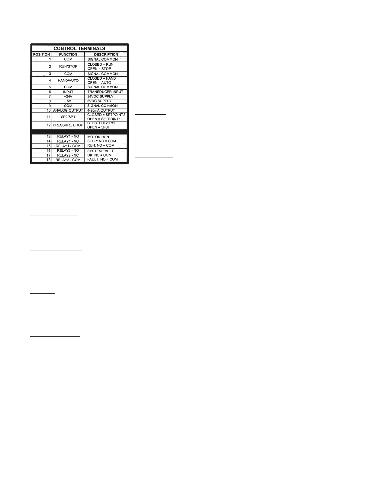
INPUT AND OUTPUT FUNCTIONS
Section 8
The control terminal strips allow for a variety of input and output functions.
Warning: Turn off all power to the controller before wiring devices to the
control terminals.
Warning: Inputs RUN/STOP, HAND/AUTO, SP2/SP1 and PRESSURE DROP
are switch inputs. Do not connect power to these inputs or damage to the
controller will result. Only connect non-powered switch contacts to these
inputs.
RUN/STOP: This input allows the pump/motor to be turned on and off by
an external switch. Connect the contacts of a non-powered external switch
to terminals 1 (COM) and 2 (RUN/STOP). When the switch is closed the
controller is in RUN mode (output to motor is enabled). When the switch is
open the controller is in STOP mode (output to motor is disabled).
HAND/AUTO: This input allows the controller to run the motor at
full speed without the use of a pressure transducer. This input can be
controlled by an external non-powered switch. Connect the contacts
of a non-powered external switch to terminals 3 (COM) and 4 (HAND/AUTO). When the switch is closed the
controller is in HAND mode. While in HAND mode the RUN/STOP input is used to start and stop the motor and
the pressure transducer input is ignored. When the switch is open the controller is in AUTO mode. While in
AUTO mode the controller uses the pressure transducer feedback to control the speed of the motor.
INPUT and +24V: These terminals are the transducer feedback and transducer power supply. Connect the
white lead from the transducer cable to terminal 6 (INPUT). Connect the brown lead from the transducer cable to
terminal 7 (+24V). Connecting the drain (bare) wire to the chassis allows grounding of the case of the pressure
transducer. The controller is congured with a 300 PSI 4-20mA output pressure transducer.
ANALOG OUTPUT: This output is a 4-20mA signal based on motor speed (4mA = 0Hz, 20mA = 60Hz) and can
be connected to external monitoring or external control devices. Connect terminal 10 (ANALOG OUTPUT) to the
4-20mA input of the external device. Connect terminal 9 (COM) to the negative side of the current loop on the
external device. The external device must have an input resistance (impedance) in the range of 45Ω to 250Ω. The
maximum output voltage is 24V.
SP2/SP1: This input allows the system to operate at one of 2 pressure settings. This input can be controlled by
an external non-powered switch. Connect the contacts of a non-powered external switch to terminals 5 (COM)
and 11 (SP2/SP1). When the switch is closed pressure set point 2 is enabled (preset to 75 PSI when used with a
300 PSI transducer). When the switch is open pressure set point 1 is enabled (preset to 50 PSI when used with a
300 PSI transducer).
PRESSURE DROP: This input allows the user to select the amount of pressure drop in the system before the
pump starts. This input can be controlled by an external non-powered switch. Connect the contacts of a nonpowered external switch to terminals 5 or 9 (COM) and 12 (PRESSURE DROP). When the switch is closed the
system pressure will drop 20 PSI (when used with a 300 PSI transducer) before restarting the pump. When the
switch is open the system pressure will drop 5 PSI (when used with a 300 PSI transducer) before restarting the
pump.
RUN RELAY: This output indicates when the pump/motor is running. This output can be used to control power
to a light, an alarm or other external device. When the pump/motor is off terminal 13 (RELAY1 – NO) will be open
and terminal 14 (RELAY 1 – NC) will be connected to terminal 15 (RELAY1 – COM). When the pump/motor is on
terminal 13 (RELAY1 – NO) will be connected to terminal 15 (RELAY1 – COM) and terminal 14 (RELAY 1 – NC) will
be open. The relay rating is 250Vac, 5 amps maximum.
FAULT RELAY: This output indicates when the system is faulted. This output can be used to control power to a
light, an alarm or other external device. When the system is not faulted terminal 16 (RELAY2 – NO) will be open
and terminal 17 (RELAY 2 – NC) will be connected to terminal 18 (RELAY2 – COM). When the system is faulted
terminal 16 (RELAY2 – NO) will be connected to terminal 18 (RELAY2 – COM) and terminal 17 (RELAY 2 – NC) will
be open. The relay rating is 250Vac, 5 amps maximum.
Page 19
Page 20

Hazardous
voltage
DANGER
TROUBLESHOOTING
Section 9
General
The Aquavar SPD drives are self-diagnosing controllers. If a problem occurs, observe the Status Code Indicator
Light on the front of the unit. No Status Code Indicator Light means either no or low input voltage (less than
140Vac).
DANGER
Status Code Indicator Light is not a voltage indicator! Always turn off disconnect switch and
circuit breaker and wait 5 minutes before servicing. High voltage may still remain on controller.
Refer to the status code label on the side of the controller access cover to diagnose system errors.
See the following diagram.
Use the following table to help troubleshoot problems.
Red Flashes Fault Code Restart Action
Constant Replace Controller Controller will not restart. Power must be reset to clear the fault.
2 Blinks No Water / Loss of Prime
3 Blinks Sensor Fault
4 Blinks Pump or Motor Bound
5 Blinks Short Circuit / Ground Fault Controller will not restart. Power must be reset to clear the fault.
6 Blinks Input Phase Loss
7 Blinks Temperature
8 Blinks Over Voltage
9 Blinks Motor Overload Controller will restart automatically.
Page 20
Controller will restart automatically according to the No Water Restart
Time switches (switches 3&4 of bank 2).
Controller will restart automatically when the sensor signal is within the
valid operating range.
Controller will restart automatically 5 times. After 5 faults the power
must be reset to clear the fault.
Controller will restart automatically 5 times. After 5 faults the power
must be reset to clear the fault.
Controller will restart automatically when temperature is within the
operating range of the controller.
Controller will restart automatically when the input voltage is within the
operating range of the controller.
Page 21
TROUBLESHOOTING
NO LIGHT
Controller Status Description
Check the input voltage to the controller. Measure the input voltage be-
Low/No Input Voltage
tween phases using an AC Voltmeter. This voltage should be greater than
140Vac for the status indicator light to turn on.
GREEN LIGHT CODES
Flashes Controller Status Description
Constant Green Light indicates the pump is off. The system is in Standby
Constant Standby
Blinking Pump Running Flashing Green Light indicates the pump is running.
mode when there is no ow in the system and the pressure setting has
been reached or the RUN/STOP input is set to STOP (open switch).
ORANGE LIGHT CODES
Flashes Controller Status Description
Constant Orange Light indicates the system input voltage is low. For 230V
Constant Low Input Voltage
Blinking
No Water/Loss of Prime
Fault Disabled
units, the orange light will be indicated when the input voltage is between
140Vac and 170Vac. For 460V units, the orange light will be displayed
when the input voltage is between 140Vac and 310Vac.
Blinking Orange Light indicates the No Water/Loss of Prime Fault is dis-
abled and the pump/motor is running. For details see 2 Blinks under Red
Light Codes.
Number of
Flashes
Constant Controller Error
2 Blinks No Water/Loss of Prime
Controller Status Description
RED LIGHT CODES
Internal controller fault. The controller may be internally damaged. Verify
the error by turning power off, waiting 5 minutes then apply power. If the
error persists, replace controller.
This fault can be caused by:
• Water supply level in well falls below suction inlet of pump.
• Plugged suction screen.
• Restriction in pipe between pump and pressure sensor.
• Air bound pump.
• Deadheaded pump, pump running against a closed valve.
• Filling long irrigation lines on start-up**
• Incorrect setting of Motor Overload Setting switches.
In systems where the motor operates at less than Service Factor Amps
the controller may show a false No Water/Loss of Prime fault. Reducing the motor overload setting will eliminate the false readings.
If problem persists, please verify supply capacity.
The controller will automatically restart according to the No Water Restart
Time switches.
** Controllers with software revision A3 or later allow the user to disable
this function by holding down both push buttons for 5 seconds while the
pump/motor is running. While the no water/loss of prime function is dis-
abled, the status LED will blink orange while the pump/motor is running.
To re-enable the function, hold down both push buttons for 5 seconds
while fault is disabled and the pump/motor is running.
It is not recommended to keep the No Water/Loss of Prime fault disabled
after the system has been primed. Doing so can result in damage to the
pump.
Page 21
Page 22
TROUBLESHOOTING
Number of
Flashes
3 Blinks Sensor Fault
Controller Status Description
RED LIGHT CODES
This fault can be caused by:
• Disconnected sensor. Disconnect sensor from sensor cable connector
and reconnect to ensure a good connection.
• Disconnected sensor cable lead inside the controller. Check for loose
wires where the sensor cable connects to the circuit board by tugging
on each wire.
• Broken wire in the sensor cable.
• Miswired sensor cable. Check that the wires are connected to the cor-
rect terminals on the control terminal block. Connect terminal 7 (24VDC
SUPPLY) to the Brown wire. Connect terminal 6 (TRANSDUCER INPUT)
to the White wire. Connect the Drain wire to the chassis.
• Vacuum in the system. A vacuum condition may exist in the system piping. Remove the sensor from the piping to release the vacuum.
• Failed sensor. To diagnose this failure a meter capable of reading milliamperes (mA) and DC voltage (VDC) is required.
- Set the meter to read DC voltage (VDC)
- Place the black lead on terminal 5 (COM) and the red lead on terminal
7 (24VDC SUPPLY)
- If functioning properly, the DC voltage will be 24VDC +/- 15%. If this
voltage is not present, disconnect all control terminals and repeat the
measurement. If voltage does not recover, replace controller.
- Disconnect the White wire in the sensor cable from terminal 6.
- Set the meter to read DC current (mA)
- Connect the black lead from the meter to terminal 6 (TRANSDUCER
INPUT)
- Connect the red lead from the meter to the White wire in the sensor
cable.
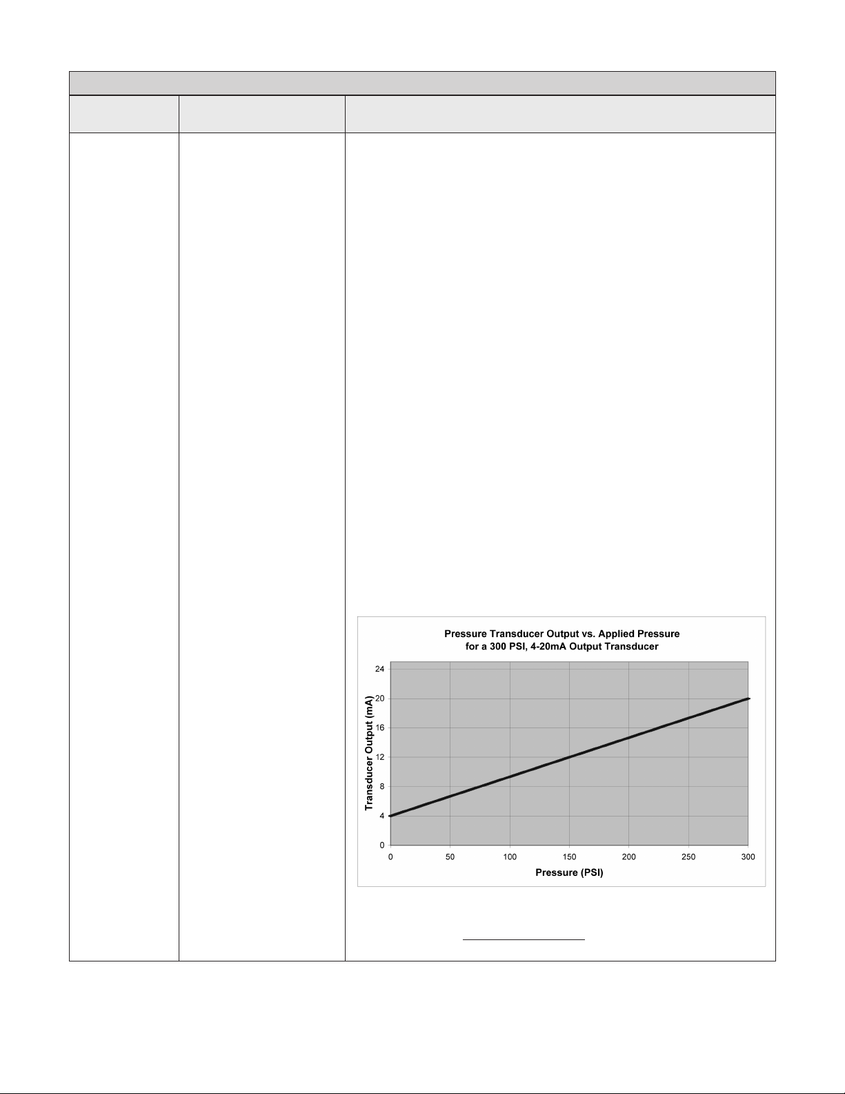
- The meter will display the output of the sensor. If functioning properly,
the output of the sensor will be between 4mA and 20mA depending
on the pressure in the system. Refer to the chart below to determine
the sensor feedback at various pressures.
Page 22
The following formula gives the transducer output based on applied
pressure:
Output Current =
Pressure Range
Output Current Range
[ ] ( )
x System Pressure + 4mA
Page 23

TROUBLESHOOTING
Number of
Flashes
3 Blinks
(continued)
4 Blinks Pump or Motor Bound
5 Blinks Short Circuit/Ground Fault
6 Blinks Input Phase Loss
7 Blinks Temperature
Controller Status Description
Sensor Fault
(continued)
RED LIGHT CODES
Where:
• Output Current is the transducer output
• Output Current Range is the maximum output signal of the transducer
minus the minimum output signal of the transducer. In this case:
Output Current Range = 20mA – 4mA, or 16mA
• Pressure Range is the pressure that corresponds to the maximum out-
put signal. For a 300 PSI transducer the Pressure Range =
300 PSI – 0 PSI = 300 PSI
• System Pressure is the system pressure as read on the pressure gauge.
This fault can be caused by:
• Mechanical binding from debris in pump.
• Electrical failure of the motor.
• Incorrect setting of Motor Overload Setting switches.
• Incorrect rotation.
• Motor phase loss.
This fault will be displayed if the output current exceeds 125% of the
controller rating. The controller will attempt to restart 5 times. If the condition persists the controller will lock out and will need to be reset. Verify the
error by turning power to controller off for 5 minutes and then on. Pump/
Motor/Wiring must be checked if fault persists.
This fault can be caused by:
• Electrical failure of the motor
• Electrical failure of wiring between controller and motor.
This fault will be displayed if the output current exceeds 150% of the
controller rating. Verify the error by turning power to controller off for 1
minute and then on. If error persists, motor and wiring between controller
and motor must be checked. Turn power off for 5 minutes. Remove the
three motor wires from the terminal block. Check output wiring and motor
for shorting phase to phase and phase to ground. Refer to motor's manual
for information on resistance readings and megger readings.
This fault can be caused by:
• Disconnected input power phase.
• Incorrect Motor Overload Setting switches. When using single phase
input power the Motor Overload Setting switches must be set to 50% or
lower.
For three phase input operation; this fault will be displayed if input voltage imbalance is more than 3%. The controller will attempt to restart 5
times. If the condition persists the controller will lock out and will need to
be reset.
This fault can be caused by:
• High ambient temperature. The maximum ambient temperature rating
is 122ºF (50ºC).
• Low ambient temperature. The minimum ambient temperature rating is
-22ºF (-30ºC).
This fault will be displayed if the ambient temperature is greater than
122ºF (50ºC) or less than -22ºF (-30ºC). Do not install the controller where
it will be exposed to direct sunlight. Check for a fan failure. The fans on the
back of the controller will turn on only when needed. The fans will turn on
when the motor is running and the heatsink temperature reaches 104ºF
(40ºC).
Page 23
Page 24

TROUBLESHOOTING
Number of
Flashes
8 Blinks Over Voltage
9 Blinks Motor Overload
Controller Status Description
RED LIGHT CODES
This fault can be caused by:
• High input voltage.
This fault will be displayed if the phase to phase input voltage is greater
than 275V for 230V units and 560V for 460V units.
This fault can be caused by:
• Mechanical binding from debris in pump.
• Electrical failure of the motor.
• Incorrect setting of Motor Overload Setting switches.
• Incorrect rotation.
The controller will protect the motor from over current by limiting the cur-
rent applied to the motor. The current limit is set according to the Motor
Overload Setting switches. This fault is displayed if the output frequency is
reduced to limit the current to the motor by more than 10Hz for 5 minutes.
Page 24
Page 25
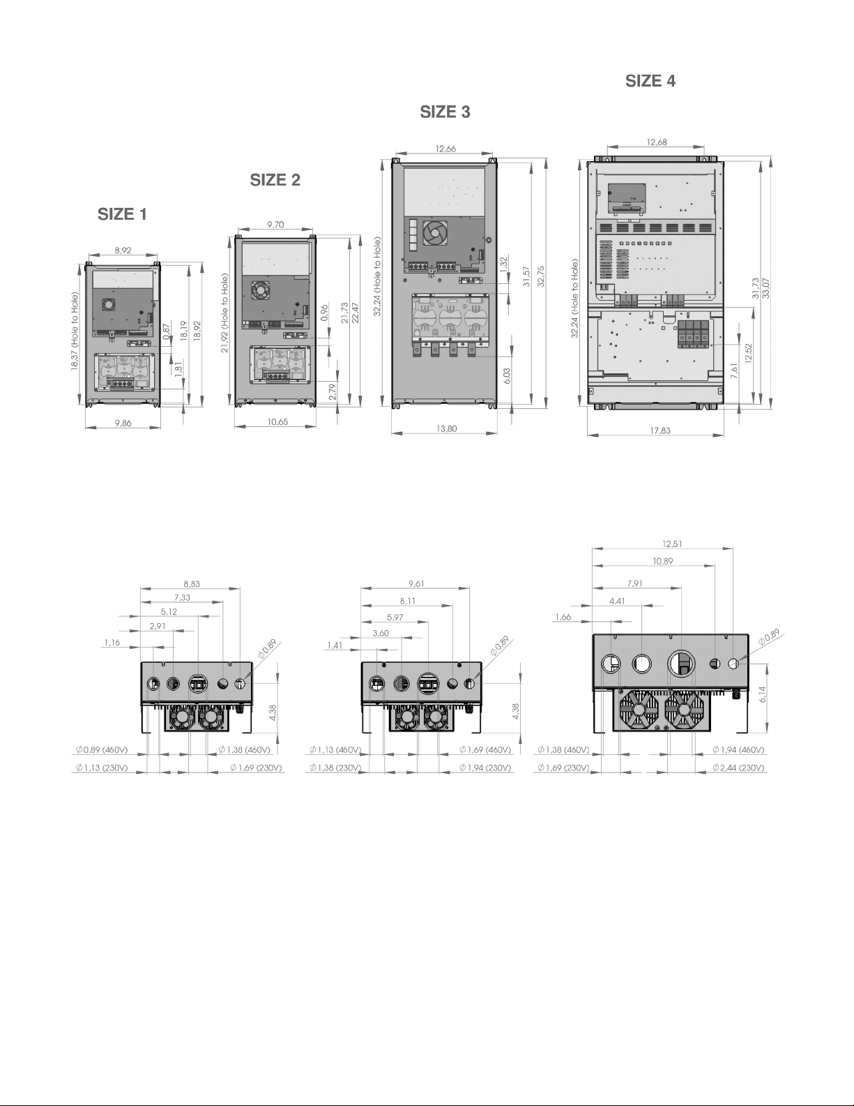
CONTROLLER DIMENSIONS
Page 25
Page 26

APPENDIX: INPUT WIRE SIZING CHARTS
Maximum Allowable Conductor Length in Feet (40˚C Ambient, 5% drop)
Ratings Conductor Size for 75˚C Rated Wire (Lengths in Bold Require 90˚C Rated Wire)
14 12 10 8 6 4 3 2 1 1/0 2/0 3/0 4/0 250 300 350 400 500 600 750 1000
Input
Current
SFA
Motor
HP
Motor
Input
Controller
2 7.6 17.6 112 185 306 495 776 1243 1566 1980 2496 3152 3979
3 10.1 23.3 224 367 579 931 1174 1485 1874 2368 2991 3778
5 17.5 40.4 321 524 666 846 1071 1356 1717 2171 2740 3238 3889
230V,
1Ø Input
7 1/2 26.4 61.0 333 428 548 697 886 1127 1427 1805 2136 2568 3005 3440
10 33.0 76.2 331 427 547 698 891 1132 1434 1700 2045 2395 2744 3421
15 46.0 106.2 373 482 622 794 1012 1204 1451 1702 1954 2440 2942 3696
2 7.6 8.9 276 444 715 1138 1774 2832 3561
3 10.1 11.9 203 329 534 853 1332 2128 2677 3383
5 17.5 20.6 177 297 484 761 1221 1539 1946 2454 3101 3915
7 1/2 26.4 31.1 310 494 800 1011 1282 1619 2048 2588 3271
10 33.0 38.8 240 387 632 802 1019 1289 1632 2065 2611 3294 3893
230V,
3Ø Input
15 46.0 54.1 264 440 563 719 912 1159 1471 1862 2353 2784 3345 3914
20 60.0 70.6 418 538 687 876 1116 1416 1793 2124 2554 2990 3425
25 76.0 89.4 410 528 677 868 1104 1402 1665 2004 2349 2693 3359
30 94.0 110.6 531 687 878 1119 1333 1606 1885 2165 2705 3260
2 3.8 4.5 1130 1561 2495 3956
3 5.3 6.2 804 1114 1785 2833
5 8.5 10.0 489 684 1104 1760 2745
7 1/2 13.5 15.9 252 414 682 1098 1719 2751 3464
10 17.2 20.2 313 524 853 1341 2152 2712 3430
460V
15 23.0 27.1 377 625 991 1598 2018 2555 3225
20 30.0 35.3 464 745 1211 1535 1947 2461 3115 3940
25 37.0 43.5 590 968 1232 1566 1984 2514 3184
30 47.0 55.3 744 952 1217 1545 1963 2492 3155 3988
Lengths in BOLD require 90ºC wire Input connections for models SPD20300 and SPD20300F always require 90ºC wire
Page 26
Page 27

APPENDIX: OUTPUT WIRE SIZING CHARTS
Maximum Allowable Conductor Length in Feet (40˚C Ambient, 5% drop)
Ratings Conductor Size for 75˚C Rated Wire
14 12 10 8 6 4 3 2 1 1/0 2/0 3/0 4/0 250 300 350 400 500 600 750 1000
SFA
Motor
HP
Motor
Input
Controller
2 7.6 327 525 843 1340 2089 3333
3 10.1 242 391 631 1006 1569 2505 3152 3981
5 17.5 129 214 355 573 899 1440 1813 2293 2890 3651
7 1/2 26.4 224 371 587 946 1195 1513 1909 2413 3049 3852
10 33.0 171 289 463 751 950 1205 1522 1925 2435 3077 3880
230V
15 46.0 320 526 670 854 1081 1371 1737 2198 2775 3281 3941
20 60.0 233 391 502 643 818 1040 1322 1675 2118 2507 3013 3526
25 76.0 295 384 495 633 808 1032 1310 1661 1969 2368 2773 3177 3961
30 94.0 386 498 639 821 1046 1330 1580 1902 2231 2558 3192 3848
2 3.8 1332 2123 3391
3 5.3 950 1517 2427 3851
5 8.5 582 935 1505 2395 3733
7 1/2 13.0 366 597 972 1556 2432 3888
10 16.5 277 458 756 1218 1909 3056 3848
460V
15 23.0 309 525 860 1356 2180 2750 3480
20 30.0 384 644 1025 1658 2096 2656 3354
25 37.0 507 817 1331 1687 2141 2708 3428
30 47.0 624 1028 1311 1669 2115 2682 3399
Lengths in BOLD require 90ºC wire
Page 27
Page 28

XYLEM INC. LIMITED WARRANTY
This warranty applies to all SPD and SPD Plus Drives sold by Xylem Inc.
Any part or parts found to be defective within the warranty period shall be replaced at no charge to the dealer during the warranty period. The warranty period shall exist for a
period of twenty-four (24) months from date of installation or thirty (30) months from date of manufacture, whichever period is shorter.
A dealer who believes that a warranty claim exists must contact the authorized Xylem Inc. distributor from whom the pump was purchased and furnish complete details
regarding the claim. The distributor is authorized to adjust any warranty claims utilizing the Xylem Inc. Customer Service Department.
The warranty excludes:
(a) Labor, transportation and related costs incurred by the dealer;
(b) Reinstallation costs of repaired equipment;
(c) Reinstallation costs of replacement equipment;
(d) Consequential damages of any kind; and,
(e) Reimbursement for loss caused by interruption of service.
For purposes of this warranty, the following terms have these definitions:
(1) “Distributor” means any individual, partnership, corporation, association, or other legal relationship that stands between Xylem Inc. and the dealer in purchases,
consignments or contracts for sale of the subject pumps.
(2) “Dealer” means any individual, partnership, corporation, association, or other legal relationship which engages in the business of selling or leasing pumps to customers.
(3) “Customer” means any entity who buys or leases the subject pumps from a dealer. The “customer” may mean an individual, partnership, corporation, limited liability
company, association or other legal entity which may engage in any type of business.
THIS WARRANTY EXTENDS TO THE DEALER ONLY.
Xylem Inc.
2881 East Bayard Street Ext., Suite A
Seneca Falls, NY 13148
Phone: (800) 453-6777
Fax: (888) 322-5877
www.centripro.com
CentriPro and Aquavar SPD are trademarks of Xylem Inc. or one of its subsidiaries.
© 2012 Xylem Inc. IM213 Revision Number 4 October 2013
Page 29

MANUAL DE INSTRUCCIÓN
IM213R04
™
Aquavar SPD
Control de Bomba de Velocidad Variable
INSTRUCCIONES DE INSTALACIÓN, FUNCIONAMIENTO Y MANTENIMIENTO
Page 30

ÍNDICE
Instrucciones importantes sobre seguridad ........................................................................................................ 31
Componentes del sistema ...................................................................................................................................... 32
Diseño del sistema ................................................................................................................................................... 33
Tuberías: .................................................................................................................................................................... 35
Montaje del Controlador ......................................................................................................................................... 37
Suministro de energía eléctrica y cableado ..........................................................................................................37
Arranque del sistema (Conexiones de entrada/salida, ajuste de los interruptores,
rotación del motor) ............................................................................................................................................... 43
Funciones de entrada y salida (Terminales de control) ...................................................................................... 48
Localización y resolución de problemas ...............................................................................................................49
Dimensiones del Controlador ............................................................................................................................... 54
Apéndice (Tabla de determinación del tamaño de alambre) ............................................................................. 55
Garantía limitada ...................................................................................................................................................... 58
NOTA:
• Utilice únicamente alambre de cobre.
• Apropiado para su uso en un microambiente de contaminación de grado 2.
• Protección contra sobrecarga del motor provista al 100% de la corriente de entrada a plena carga.
• Para mantener la integridad de las características ambientales del gabinete, deberán cerrarse todas
las aberturas de los equipos con clasicación 3, 3R, 3S, 4, 4X, 6 ó 6P.
• Rango Máximo de la Temperatura Ambiente, de -22º F a 122º F.
• Humedad Máxima: 95% a 104º F sin condensación.
• El regulador es el TIPO clasicado 3R (Raintight) así que puede ser localizado al aire libre
Page 30
Page 31

PELIGRO
ADVERTENCIA
PRECAUCIÓN
INSTRUCCIONES IMPORTANTES SOBRE SEGURIDAD
Sección 1:
Importante: Lea toda la información sobre seguridad antes de instalar el
Controlador.
NOTA:
Este es un SÍMBOLO DE ALERTA DE SEGURIDAD. Al ver este símbolo en el controlador, en
la bomba o en este manual, busque una de las siguientes palabras de alerta y manténgase
atento dada la posibilidad de que se produzcan lesiones personales o daños a la propiedad.
Obedezca todos los mensajes que siguen a este símbolo para evitar lesiones o muerte.
Indica una inminente situación peligrosa que, de no ser evitada, podría provocar la
muerte o lesiones graves.
Indica una situación potencialmente peligrosa que, de no ser evitada, podría provocar la
muerte o lesiones graves
Indica una situación potencialmente peligrosa que, de no ser evitada, podría provocar la
muerte o lesiones graves.
PRECAUCIÓN
Si se utiliza sin el símbolo de alerta de seguridad, indica una situación potencialmente
peligrosa que, de no ser evitada, podría resultar en daños a la propiedad.
NOTA Indica que son instrucciones especiales muy importantes y que deben ser respetadas.
NOTA
El personal de operaciones deberá leer, comprender y respetar todas las instrucciones referidas al
funcionamiento. CentriPro no acepta responsabilidad alguna por daños o irregularidades operativas
que se produzcan como resultado del no cumplimiento de las instrucciones referidas al funcionamiento.
1. Este manual tiene por objeto asistir en la instalación, operación y reparación del sistema y debe guardarse
junto al sistema.
2. La instalación y el mantenimiento DEBEN estar a cargo de personal debidamente capacitado y calicado.
3. Repase todas las instrucciones y advertencias antes de hacerle cualquier trabajo al sistema.
4. Cualquier calcomanía relativa a seguridad DEBE dejarse colocada sobre el controlador y/o
PELIGRO
Voltaje
peligrosa
5. El sistema DEBE desconectarse del suministro principal de energía eléctrica antes de intentar
PRECAUCIÓN
Presión
Peligrosa
sistema de bombeo.
realizar alguna operación o mantenimiento a la parte eléctrica o mecánica del sistema. Si no se
desconecta la corriente eléctrica antes de intentar realizar cualquier ope-ración o mantenimiento,
esto puede traducirse en electrochoque, quemaduras o muerte.
6. Cuando el sistema está en funcionamiento, el motor y la bomba pueden arrancar inespera
damente y causar serias lesiones.
Page 31
Page 32

Voltaje
peligrosa
PELIGRO
Presión
Peligrosa
PRECAUCIÓN
COMPONENTES DEL SISTEMA
Sección 2:
Tenga a bien revisar los componentes SPD, asegurarse de contar con todas las partes y estar familiarizado
con sus nombres. Asegúrese de inspeccionar todos los componentes que provee CentriPro para saber si se
produjeron daños en el transporte.
Controlador SPD de Velocidad Variable:
1. Controlador SPD
2. Transductor de Presión con Cable
3. Tapas de chapa para conductos
ADVERTENCIA
NO ENCIENDA la unidad o ponga en funcionamiento la bomba hasta terminar todas las
conexiones eléctricas y de plomería, especialmente la conexión del sensor de presión. La bomba
no debe funcionar en seco. Todo trabajo eléctrico debe ser realizado por un técnico calicado.
Siempre respete el Código Nacional Eléctrico (NEC - National Electric Code), o el Código
Eléctrico Canadiense, así como todo código local, estatal y provincial. Debe dirigir sus preguntas
sobre el código a su inspector local en electricidad o agencia de aplicación de códigos. El no
respetar los códigos eléctricos y las normas de seguridad de OSHA puede resultar en lesión
personal o daño a equipos. El no respetar las instrucciones de instalación del fabricante puede resultar
en electrochoque, peligro de incendio, lesión personal o muerte, daños a los equipos, funcionamiento
insatisfactorio, y puede anular la garantía del fabricante.
Información sobre el código de producto del controlador
SPD Y XXXX F
F = con el ltro de la salida para las aplicaciones sumergibles de la bomba
BLANK / EN BLANCO = sin el ltro para las aplicaciones de la tierra antedicha/de la
bomba centrífuga
4 dígitos para HP
5 HP = 0050
7.5 HP = 0075
10 HP = 0100
15 HP = 0150
20 HP = 0200
25 HP = 0250
30 HP = 0300
1 dígito para voltaje de entrada
230 voltio = 2
460 voltio = 4
575 voltio = 5
SERIE
Page 32
Page 33

DISEÑO DEL SISTEMA
Sección 3:
NOTA
el diseño de los sistemas DEBE estar a cargo únicamente de técnicos calicados y cumplir con todos los
requisitos de los códigos locales y estatales pertinentes.
Los siguientes diagramas muestran a un sistema típico utilizando el Controlador SPD_ _ F de Presión Constante,
con el ltro. El Diagrama #1 muestra un armado clásico para el sistema sumergible.
1
2
SUMINISTRO DE
CORRIENTE
L1
L2
L3
TIERRA
6
T1
T2
T3
TIERRA
4
5
8
3
FLUJO
7
1 CONTROLADOR SPD_F
2 DISYUNTOR DE FUSIBLE
11
3 INDICADOR DE PRESIÓN
4 TANQUE DE AIRE DE DIAFRAGMA
5 TRANSDUCTOR DE PRESIÓN
6 SALIDA TRIFÁSICA (SIEMPRE)
7 VÁLVULA DE VERIFICACIÓN DE DESCARGA
8 VÁLVULA DE COMPUERTA (MUY RECOMENDADA)
9 EXTREMIDAD DE LA BOMBA SUMERGIBLE
10 MOTOR SUMERGIBLE (TRIFÁSICO)
11 VÁLVULA DE ALIVIO DE PRESIÓN
NOTA: PARA LA ENTRADA MONOFÁSICA, CONECTE L1 Y L3, LUEGO
AJUSTE LOS INTERRUPTORES DE SOBRECARGA DEL MOTOR AL 50% DE
LA POTENCIA INDICADA DEL CONTROLADOR, O EN MENOS.
9
10
Page 33
Page 34

DISEÑO DEL SISTEMA
Sección 3 (continuación)
El Diagrama #2 muestra un armado utilizado para la conexión con el agua del municipio.
1
2
SUMINISTRO DE
CORRIENTE
L1
L2
L3
TIERRA
5
AIRE
6
T1
7
9
SUCCIÓN
8
T2
T3
TIERRA
SALIDA TRIFÁSICA
AL MOTOR
4
9
10
FLUJO
8
3
1 CONTROLADOR SPD 6 TANQUE DE AIRE DE DIAGRAGMA
2 DISYUNTOR DE FUSIBLE 7 MOTOR TRIFÁSICO
3 BOMBA CENTRÍFUGA 8 VÁLVULA DE COMPUERTA (VÁLVULA O LLAVE DE BOLA
4 VÁLVULA DE VERIFICACIÓN 9 INDICADOR DE PRESIÓN
5 TRANSDUCTOR DE PRESIÓN (ENSAMBLAJE DE CABLES) 10 VÁLVULA DE ALIVIO DE PRESIÓN
NOTAS: Para la corriente eléctrica de entrada monofásica utilice L1 y L3 y ajuste los interruptores de sobrecarga del
motor al 50% de la potencia del controlador, o a un porcentaje menor.
Page 34
Page 35

Presión
Peligrosa
PRECAUCIÓN
Presión
Peligrosa
PRECAUCIÓN
TUBERÍAS
Sección 4:
Generalidades
NOTA
Todo trabajo de plomería debe ser realizado por un técnico calicado. Siempre respete todos los códigos
locales, estatales y provinciales.
Una instalación adecuada requiere una válvula de alivio de presión, una rosca convencional N.P.T. hembra de ¼"
para el sensor de la presión, y un caño de dimensión apropiada. La tubería no debe ser más pequeña que las
conexiones de descarga y/o de succión de la bomba. La tubería debe mantenerse lo más corta posible. Evite
utilizar accesorios innecesarios para reducir al mínimo las pérdidas por fricción.
Algunas combinaciones de bomba y motor suministradas con este sistema pueden crear una
presión peligrosa. Seleccione las tuberías y accesorios de acuerdo con la recomendación de su
proveedor de tuberías. Consulte los códigos locales sobre requisitos de las tuberías en su zona.
Todas las juntas deben ser herméticas. Utilice cinta de Teon u otro tipo de sellador de tubos para sellar las
conexiones roscadas. Tenga cuidado cuando utilice sellador de roscas ya que cualquier exceso que entre en la
tubería podría tapar el sensor de presión.
Los accesorios o tuberías galvanizados nunca deben conectarse directamente a la carcasa o al cabezal de
descarga de acero inoxidable ya que podría producirse corrosión galvánica. Los conectores tipo arpón o púa
siempre deben sujetarse con doble abrazadera.
Tanque de presión, válvula de alivio de presión y tubería de descarga
Utilice sólo tanques “precargados” en este sistema. No utilice tanques galvanizados. Seleccione un área que
siempre esté a más de 34º F (1,1º C) para instalar el tanque, el sensor de presión y la válvula de alivio de presión.
Si éste es un lugar donde una fuga de agua o purga de la válvula de alivio de presión podría producir daños
materiales, conecte una línea de drenaje a la válvula de alivio de presión. Conecte una línea de drenaje desde
la válvula de alivio de presión a un drenaje apropiado o a un lugar donde el agua no produzca daños
materiales.
Tanque de presión, presión del sistema
Determinación del tamaño – Se utiliza un tanque con cámara (no incluida) para amortiguar el sistema
de presión durante el arranque y el apagado. Debe ser dimensionado como mínimo al 20% del total de la
capacidad de su bomba. Ejemplo: Si su bomba se ajusta para 100 GPM, entonces ajuste usted su tanque para
20 gal. del volumen total, como mínimo, sin rebajar. Hágale una carga previa a su tanque con cámara en 10-15
PSI por debajo de su sistema de presión. El controlador está preestablecido de fábrica en 50 PSI. Por lo tanto,
su tanque necesitará una precarga de 35-40 PSI. Efectúe el ajuste de precarga del tanque superior si el sistema
pierde más de 5 PSI a un ujo constante. NOTA: ¡Realice la precarga a su tanque antes de llenar con agua!
CUIDADO
La presión máxima de funcionamiento del tanque con cámara HydroPro es 125 PSI.
Page 35
Page 36

TUBERÍAS
Sección 4 (continuación)
Instalación del sensor de presión
Para instalar el sensor de presión se necesita una pieza de conexión FNPT de ¼". Instale el sensor de presión con
el conector eléctrico mirando hacia arriba a n de evitar obstruir el puerto de presión con escombros. Instale el
sensor de presión haciendo un trazado de tubería directo, lejos de codos o turbulencia. Para obtener un control
óptimo de la presión, instale el sensor de presión en el mismo trazado de tubería directo que tiene el tanque
de presión. Asegúrese de que el sensor de presión se encuentre dentro de los 10 pies del tanque de presión. Si
instala el sensor de presión lejos del tanque de presión pueden producirse oscilaciones de la presión. No instale
el sensor de presión en un lugar donde puede producirse un congelamiento. Una tubería congelada puede
causar daños al sensor de presión.
El cable del sensor de la presión se encuentra precableado al controlador. Puede acortarse el cable para
efectuar una instalación más prolija. Hay disponibilidad de cables más largos, consulte en fábrica. El largo
máximo recomendado para el cable del sensor de presión es 300 pies. Evite dejar una cola de cable del sensor
de presión ya que esto puede inducir a voltajes transitorios no deseados y ruido dentro del sistema. No extienda
el cable del sensor de presión a lo largo del cableado de entrada o salida. Mantenga una distancia mínima de 8”
entre el cable del sensor de presión y el cableado de entrada o salida.
Asegúrese de que el cable del sensor de presión esté conectado de la siguiente manera: Marrón al terminal
7 (SUMINISTRO 24VDC), Blanco al terminal 6 (ENTRADA DE TRANSDUCTOR), Drenaje al chasis. Al conectar
el alambre de drenaje al chasis en forma eléctrica se conecta la caja del sensor al chasis del controlador. En
algunos casos este alambre de drenaje debe desconectarse del chasis del controlador. En los casos en que
haya tuberías metálicas con conexión a tierra continua entre el transductor y el motor, o que el transductor se
haya instalado en tuberías metálicas con conexión a tierra, puede producirse un bucle de masa de modo que el
alambre de drenaje debe desconectarse del chasis. En los casos en que haya secciones de tuberías no metálicas
entre el transductor y el motor, o que el transductor esté instalado en tuberías sin conexión a tierra, este alambre
de drenaje debe conectarse al chasis del controlador.
Page 36
Page 37

Tension
dangereuse
DANGER
MONTAJE DEL CONTROLADOR
Sección 5:
Generalidades
Efectúe el montaje del controlador en un área bien ventilada y a la sombra, utilizando 4 tornillos. El controlador
debe montarse en posición vertical. Asegúrese de dejar 8 pulgadas de espacio libre a cada lado de la unidad. El
controlador debe estar en un lugar con una temperatura ambiente entre -22º F y 122º F. Si la instalación es a más
de 3.300 pies sobre el nivel del mar, las temperaturas ambiente deben reducirse 1% por cada 330 pies sobre los
3.300 pies. El límite de altitud para este controlador es 6.500 pies.
No lo instale a más de 6.500 pies.
NOTA
No bloquee los disipadores de calor (aletas) o ventiladores, y no coloque nada sobre las unidades.
ADVERTENCIA
La cubierta de acceso del controlador siempre debe estar rmemente aanzada a la caja de
control debido a la tensión peligrosa / peligro de descargas eléctricas en el interior de la unidad.
Puede utilizarse un cerrojo para evitar ingresos no deseados.
SUMINISTRO DE ENERGÍA ELÉCTRICA Y CABLEADO
Sección 6
Suministro de energía eléctrica
NOTA
La instalación y el mantenimiento DEBEN estar a cargo de personal debidamente capacitado y calicado.
Siempre respete el Código Nacional Eléctrico (NEC - National Electric Code), o el Código Eléctrico
Canadiense, así como todo código local, estatal y provincial cuando realice el cableado del sistema.
El tipo de transformador y la conguración de la conexión que alimenta a un dispositivo de accionamiento
juega un papel importante en su rendimiento y seguridad. Seguidamente se ofrece una breve descripción de
las conguraciones más comunes y se discurre sobre sus virtudes y desventajas. Siempre pregunte qué tipo de
sistema de energía tiene el lugar antes de calibrar el dispositivo de accionamiento.
Delta/Wye con Wye neutral con conexión a tierra
Esta conguración es una de las más comunes, si no la más común. Ofrece el reajuste del voltaje no equilibrado
con un giro de fase de 30 grados. Dependiendo de las conexiones de salida del dispositivo de accionamiento
hacia el motor, el neutral a tierra puede ser un camino para la corriente en modo común causado por el
dispositivo de accionamiento de salida.
Page 37
Page 38

Voltaje
Peligroso
ADVERTENCIA
Voltaje
Peligroso
ADVERTENCIA
SUMINISTRO DE ENERGÍA ELÉCTRICA Y CABLEADO
Sección 6 (continuación)
Delta/Delta con conexión a tierra
Es otra conguración habitual que permite reajustar el voltaje sin cambio de fase entre la entrada y la salida.
Nuevamente, dependiendo de las conexiones de salida del dispositivo de accionamiento hacia el motor,
el neutral a tierra puede ser un camino para la corriente en modo común causado por el dispositivo de
accionamiento de salida.
In this case the line to ground voltage on the phases that are not grounded will be equal to the phase to phase
voltage. This voltage can exceed the voltage ratings of the EMC lter and input MOV protection devices. This can
cause catastrophic controller failure if the line to ground EMC lter and input MOV protection devices are not
disconnected. Refer to Disconnecting EMC Filter and MOVs for details on line to ground voltage limitations and
disconnecting these devices.
ADVERTENCIA
If the secondary of the transformer is a delta with a grounded leg (corner grounded delta), the
line to ground EMC lter components and line to ground MOV protection must be disconnected
or damage to the controller can result.
Circuito secundario sin conexión a tierra
La puesta a tierra del secundario del transformador es esencial para la seguridad no sólo del personal sino del
funcionamiento del dispositivo accionador. El hecho de dejar al secundario otando puede dar lugar a voltajes
peligrosamente altos entre el chasis del dispositivo de accionamiento y los componentes de la estructura
eléctrica interna. En muchos casos, este voltaje podría exceder las características del ltro EMC y de los
dispositivos de protección MOV provocando una falla catastróca. En todos los casos, la corriente de entrada
al dispositivo de accionamiento debe referenciarse a tierra. Si el transformador no puede conectarse a tierra,
entonces se deberá instalar un transformador de aislamiento con el secundario del transformador conectado a
tierra.
In this conguration the line to ground voltage from the incoming power supply may exceed the voltage rating
of the line to ground EMC lter components and line to ground MOV protection. This can cause catastrophic
controller failure if the line to ground EMC lter and input MOV protection devices are not disconnected. Refer
to Disconnecting EMC Filter and MOVs for details on line to ground voltage limitations and disconnecting these
devices.
ADVERTENCIA
Si se utiliza un sistema eléctrico que tiene un secundario sin conexión a tierra, la línea para poner
a tierra los componentes del ltro EMC y la línea para poner a tierra la protección MOV deberán
ser desconectadas, o de lo contrario podrá dañarse el controlador.
Page 38
Page 39

Voltaje
Peligroso
ADVERTENCIA
SUMINISTRO DE ENERGÍA ELÉCTRICA Y CABLEADO
Sección 6 (continuación)
Para retirar la línea destinada a poner a tierra a los componentes del ltro EMC, ubique al puente que se muestra
más abajo. El puente se encuentra en el lado izquierdo del controlador, en el tablero principal. Vaya a la posición
desconectada que se muestra más abajo.
Conexión a tierra de la resistencia y protección contra fuga a tierra
Conectar el neutral secundario Wye a tierra por medio de un resistor es un método aceptable de conexión a
tierra. En caso de cortocircuito del secundario, cualquiera de las fases de salida a tierra no excederá el voltaje
normal de línea a línea. Esto se encuadra dentro del régimen nominal de los dispositivos MOV de protección
de entrada, en el dispositivo de accionamiento. Con frecuencia el resistor se utiliza para detectar corriente a
tierra mediante el seguimiento de la caída de voltaje asociada. Dado que la corriente a tierra de alta frecuencia
puede uir a través de este resistor, debe tenerse cuidado de conectar correctamente los conductores de
accionamiento del motor utilizando los cables y métodos recomendados. En algunos casos, la multiplicidad de
dispositivos de accionamiento en un transformador puede producir una acumulación de corriente a tierra que
puede disparar el circuito interruptor de fallo a tierra.
Open Delta (consultar a fábrica)
Este tipo de conguración es habitual en sistemas de 230 voltios. Ocasionalmente puede darse que
se disponga solamente de corriente monofásica y se requiera corriente trifásica. La técnica utiliza dos
transformadores monofásicos para derivar una tercera fase. Cuando se la utiliza para transmitir corriente a un
dispositivo de accionamiento, esta conguración debe ser reducida al 70%, aproximadamente, del régimen
establecido para un transformador. Este sistema ofrece una regulación insuciente y es posible que sólo las dos
fases conectadas a línea suministren corriente. En este caso, el dispositivo de accionamiento debe ser reducido
al 50% de su régimen nominal. (Por ejemplo: Un dispositivo de 20 HP y 230 voltios ahora se convierte en uno de
10 HP y 230 voltios.)
ADVERTENCIA
Los sistemas eléctricos "Open Delta" deben ser medidos utilizando el factor de reducción del
50%. Consulte a la fábrica.
Page 39
Page 40

SUMINISTRO DE ENERGÍA ELÉCTRICA Y CABLEADO
Sección 6 (continuación)
Desconexión del ltro y de MOVs del EMC
Para todos los reguladores, si la línea para moler voltaje de la fuente de alimentación entrante es mayor que
300Vac entonces la línea moler los componentes del ltro del EMC se deben desconectar como descritos más
abajo. Para los reguladores 230V, si la línea para moler voltaje de la fuente de alimentación entrante excede
300Vac entonces la línea para moler MOVs se debe desconectar como descrito más abajo. Para los reguladores
460V, si la línea para moler voltaje de la fuente de alimentación entrante excede 550Vac entonces la línea para
moler MOVs se debe desconectar como descrito más abajo.
Para desconectar la línea para moler componentes del ltro del EMC, localice el puente mostrado abajo. El
puente está en el lado izquierdo del regulador en el consejo principal. Muévase a la posición disconnected
mostrada abajo.
Para desconectar la línea para moler la protección de los MOV, localice el puente mostrado abajo. El puente está
situado entre la entrada de información y los bloques de terminales de salida en el consejo principal. Muévase a
la posición mostrada.
Para los reguladores de la talla de marco 1: Para los reguladores de las tallas de marco 2 y 3:
Para los reguladores de la talla de marco 4:
Page 40
Page 41

SUMINISTRO DE ENERGÍA ELÉCTRICA Y CABLEADO
Conexión monofásica
Los pequeños dispositivos de accionamiento, con extremo frontal recticador de diodo, es posible que tengan
una salida trifásica con una entrada monofásica. Solamente se utiliza una parte del puente de entrada trifásica.
La corriente continua ondulada preferentemente se convierte en 120 Hz antes que en 360. Esto signica una
mayor demanda sobre los componentes del ltro de CC (batería de condensadores y transformador reductor
de CC). Como resultado, el dispositivo de accionamiento debe ser reducido al 50% de la corriente.
La siguiente tabla muestra los valores de la corriente de salida a plena carga del controlador cuando se utiliza
corriente monofásica o trifásica. Si se utiliza alimentación monofásica, los interruptores de sobrecarga del motor
deben jarse al 50% o menos.
Régimen de la Corriente
Voltaje de
Suministro
208/230
460
Tamaño de
Estructura
1
2
3
4
1
2
3
Número de
Modelo
SPD20050
SPD20050F
SPD20075
SPD20075F
SPD20100
SPD20100F
SPD20150
SPD20150F
SPD20200
SPD20200F
SPD20250
SPD20250F
SPD20300
SPD20300F
SPD40050
SPD40050F
SPD40075
SPD40075F
SPD40100
SPD40100F
SPD40150
SPD40150F
SPD40200
SPD40200F
SPD40250
SPD40250F
SPD40300
SPD40300F
Régimen Nominal de HP
Entrada
Trifásica
5.0 2.0 17.8 8.1
7.5 3.0 26.4 10.9
10.0 5.0 37.0 17.8
15.0 7.5 47.4 26.4
20.0 10.0 60.6 33.0
25.0 12.0 76.0 40.2
30.0 15.0 94.0 47.4
5.0 8.9
7.5 13.2
10.0 18.5
15.0 23.7
20.0 30.3
25.0 37.5
30.0 47.0
Entrada
Monofásica
de Salida del Controlador a
Plena Carga
Entrada
Trifásica
Entrada
Monofásica
Page 41
Page 42

SUMINISTRO DE ENERGÍA ELÉCTRICA Y CABLEADO
Sección 6 (continuación)
Conductos, alambres y determinación del tamaño de fusibles
Se recomienda el uso de conductos metálicos con conectores de conductos metálicos en todas las conexiones
eléctricas. Utilícese el NEC o CEC para determinar el tamaño de conducto requerido por la aplicación.
Utilice la tabla siguiente como referencia para conocer el tamaño mínimo de alambre permitido para cada
controlador. Advierta que estos tamaños de alambre no están ajustados para caídas de voltaje producto de
largas extensiones de cable. Utilice como referencia la tabla de determinación del tamaño de alambres, que
aparece en el apéndice, para determinar la longitud máxima del cable de entrada. Remítase al manual del
motor para averiguar la longitud máxima del cable de salida. La máxima caída de voltaje recomendada, tanto
en el cable de entrada como en el de salida, combinados, es del 5%. Las tablas estándar de determinación del
tamaño de alambres muestran longitudes máximas de cable solamente para cables de entrada o de salida.
Debido a esto, las longitudes informadas en la tabla deben ajustarse de forma tal que la caída de voltaje total no
supere el 5%. Por ejemplo, si la tabla de determinación del tamaño de alambres de entrada, que aparece en el
apéndice, muestra una longitud máxima de 400' y solamente se utilizan 100', entonces sólo se utilizará el 25%
de la caída total de voltaje (caída del 1,25% ). Por lo tanto, la longitud máxima del cable de salida, leída en la
tabla de determinación del tamaño de alambres del motor, debe ser ajustada al 75% de su valor, de forma tal de
no exceder la caída máxima de voltaje del 5%.
Sólo utilice fusibles rápidos clase T. El alambre utilizado para las conexiones de la potencia de entrada en
modelos SPD20300 y SPD20300F debe tener un régimen nominal de temperatura mínima de 90ºC. La tabla
siguiente muestra los tamaños recomendados de alambres y fusibles para cada controlador. Advierta que estos
tamaños de alambre no están ajustados para caídas de voltaje producto de largas extensiones de cable.
Voltaje
208/230
460
Tamaño de
Estructura
1
2
3
4
1
2
3
Número de
Modelo
SPD20050
SPD20050F
SPD20075
SPD20075F
SPD20100
SPD20100F
SPD20150
SPD20150F
SPD20200
SPD20200F
SPD20250
SPD20250F
SPD20300
SPD20300F
SPD40050
SPD40050F
SPD40075
SPD40075F
SPD40100
SPD40100F
SPD40150
SPD40150F
SPD40200
SPD40200F
SPD40250
SPD40250F
SPD40300
SPD40300F
Corriente de
salida a carga
HP Nominal
plena
17.8 5.0 30.0 7700
26.4 7.5 40.0 11400
37.0 10.0 50.0 16000
47.4 15.0 70.0 20500
60.6 20.0 80.0 26200
76.0 25.0 110.0 32800
94.0 30.0 135.0 40600
8.9 5.0 15.0 7700
13.2 7.5 20.0 11400
18.5 10.0 30.0 16000
23.7 15.0 40.0 20500
30.3 20.0 50.0 26200
37.5 25.0 60.0 32400
47.0 30.0 70.0 40600
Tamaño de
fusible
Tamaño de
generador
(VA)
Page 42
Page 43

Voltaje
Peligroso
ADVERTENCIA
Voltaje
peligrosa
PELIGRO
SUMINISTRO DE ENERGÍA ELÉCTRICA Y CABLEADO
Sección 6 (continuación)
Requisitos para la corriente de entrada y transformador de línea
El voltaje de la línea de alimentación y la corriente del transformador deben satisfacer ciertos requisitos en
cuanto a fases y equilibrio. Si usted o su contratista a cargo de la instalación eléctrica está en duda sobre los
requisitos, el texto que sigue es una guía para la instalación. En efecto, cuando esté en duda póngase en
contacto con el proveedor del servicio de luz de su zona o con la fábrica.
Antes de conectar la corriente al controlador mida el voltaje de línea a línea y de línea a tierra desde la fuente
de alimentación. El voltaje de línea a línea debe estar en el rango de 195Vca a 265Vca (230V +/– 15%) para
modelos de 230 V, y de 391Vca a 529Vca (460V +/– 15%) para modelos de 460 V. El desequilibrio máximo de
fase a fase es +/– 3%. Si el desequilibrio de fase a fase es mayor que +/– 3% será necesario un transformador
de aislamiento. El voltaje de línea a tierra debe ser menor que el 110% del voltaje nominal de línea a línea
(230V ó 460V). Si el voltaje de línea a tierra no se encuentra en este rango, es posible que el ltro EMC y los
componentes MOV necesiten ser retirados (véase la sección referida a transformadores "secundarios sin
conexión a tierra") o que se necesite un transformador de aislamiento con un secundario con conexión a tierra.
Si se utiliza un transformador de aislamiento, la mejor elección es UNO trifásico, con seis devanados. Es mejor
un Delta primario para cancelación de la tercera armónica. Un Wye secundario evita problemas de circulación
de corriente y brinda la opción muy buscada de conectar a tierra el neutral secundario para que el estrés
tenga un voltaje mínimo y la corriente continua ondulada esté puesta a tierra. El transformador debe tener un
régimen nominal de KVA de por lo menos 1,1 veces el HP máximo conectado. Es suciente un factor K de 6 si la
impedancia del transformador es mayor al 2%. Es suciente un factor K de 5 si la impedancia del transformador
es mayor al 3%. El fabricante del transformador puede ofrecer reducir el régimen para aquellos transformadores
no clasicados como Factor K para que funcionen a los niveles de Factor K producidos por el dispositivo de
accionamiento.
Se aceptan otras conguraciones de transformadores. Pueden utilizarse tres transformadores monofásicos si
son idénticos en cuanto a la simetría y el equilibrio de fase a fase. Un neutral primario Wye conectado nunca
debe conectarse a tierra. Debe tenerse sumo cuidado con las conguraciones Delta de primarios y secundarios.
Cualquier falta de simetría fase a fase puede traducirse en corrientes circulantes y calentamiento inaceptable del
transformador.
ADVERTENCIA
Nunca utilice convertidores de fase con dispositivos de accionamiento dado que puede
producirse una disyunción molesta y posibles daños. En cambio, puede utilizar corriente de
entrada monofásica y un factor de reducción del 50%.
ARRANQUE DEL SISTEMA
Sección 7:
Conexiones de la potencia de salida
Desplace el alambre conductor del motor desde el motor o caja de conductos, a través del
conducto de metal, hasta la base del controlador. Utilice un conducto metálico y conectores de
conductos metálicos. Determine el tamaño de los conductos de acuerdo con los códigos NEC, CEC
o códigos locales. Conecte el conducto e inserte los alambres a través la segunda o tercera abertura
desde la izquierda. Elija la abertura que encaje o sea más grande que el conducto utilizado. Si la abertura es más
grande que el conducto, utilice bujes para conductos a n de ajustar el conducto al controlador.
Consulte el manual del motor para determinar el tamaño del alambre necesario para la aplicación. Asegúrese
de que la conexión a tierra hasta el motor sea continua. Conecte los alambres al bloque terminal de salida
rotulado T1/U, T2/V, T3/W, y GND (Tierra) / . Conecte el alambre a tierra hasta la terminal rotulada GND
(Tierra) / . Conecte los otros conductores de fases hasta T1/U, T2/V y T3/W.
En cuanto a CentriPro Motors se obtendrá la correcta rotación conectando T1/U al Rojo, T2/V al Negro y T3/W
al Amarillo.
Page 43
Page 44

Voltaje
peligrosa
PELIGRO
Voltaje
peligrosa
PELIGRO
Voltaje
peligrosa
PELIGRO
Voltaje
peligrosa
PELIGRO
Voltaje
peligrosa
PELIGRO
ARRANQUE DEL SISTEMA
Sección 7 (continuación)
PELIGRO
El controlador tiene una elevada fuga de corriente a tierra. Los terminales de salida marcados
"GND (tierra)" o " " deben conectarse directamente a la conexión a tierra del motor. Si el
controlador o el motor no se conecta a tierra correctamente existe el peligro de electrochoque.
Conexiones de la potencia de entrada
Asegúrese de los interruptores de desconexión o disyuntores estén de seguro en la posición OFF/
APAGADO antes de realizar esta conexión. Desplace los alambres de la corriente de entrada desde
el desconector con fusibles, a través del conducto metálico, hasta la base del controlador. Utilice
un conducto metálico y conectores de conductos metálicos. Determine el tamaño de los conductos
de acuerdo con los códigos NEC, CEC o códigos locales. Utilice la tabla de determinación del tamaño de
alambres, situada en el apéndice, para denir el tamaño de los alambres para la corriente de entrada. Conecte
el conducto e inserte los alambres dentro de la abertura situada a la extrema izquierda del controlador. Conecte
los alambres al bloque de terminales rotulado "INPUT (entrada)". Conecte el alambre a tierra al terminal rotulado
GND/ (tierra). Para la entrada trifásica conecte los alambres de la fase de entrada a L1 y L3. Para la entrada
monofásica conecte los alambres de entrada a L1 y L3. Si se utiliza alimentación monofásica, los interruptores de
sobrecarga del motor deben jarse al 50% o menos.
CUIDADO
El alambre utilizado para las conexiones de la potencia de entrada en modelos SPD20300 y SPD20300F debe
tener un régimen nominal de temperatura mínima de 90ºC.
PELIGRO
El controlador tiene una elevada fuga de corriente a tierra. Los terminales de salida marcados
"GND (tierra)" deben conectarse directamente a la conexión a tierra de la entrada del
servicio. Si el controlador o el motor no se conecta a tierra correctamente existe el peligro de
electrochoque.
NOTA
Si se utiliza potencia de entrada monofásica, los interruptores de sobrecarga del motor deben jarse al 50%
o menos; de lo contrario pueden presentarse errores molestos de pérdida en la fase de entrada.
NOTA
No utilice protección GFCI con este controlador. Se traducirá en una disyunción molesta.
PELIGRO
La Luz que Indica el Código de Estado ¡no es un indicador de voltaje! Siempre apague el
interruptor de desconexión y el disyuntor, y espere 5 minutos antes del mantenimiento.
PELIGRO
El controlador permanecerá cargado eléctricamente por 5 minutos más después de apagarlo.
Espere 5 minutos después de desconectar la corriente y antes de abrir la cubierta de acceso al
controlador, pues existe el grave peligro de electrochoque.
Ajuste de los interruptores de sobrecarga del motor
Los interruptores de ajuste de sobrecarga del motor regulan el nivel de protección de la corriente eléctrica por
sobrecarga del motor, necesario para protegerlo en caso de sobreintensidad de la corriente.
Page 44
Page 45

ARRANQUE DEL SISTEMA
Sección 7 (continuación)
Los interruptores 1,2,y 3 de la batería 1 permiten realizar el ajuste de sobrecarga
del motor. Estos interruptores ajustan la protección contra sobrecarga del motor en
forma de porcentaje del régimen de la corriente de salida del controlador a plena
carga. Elija un ajuste de sobrecarga del motor que cumpla con el régimen SFA del
motor o sea menor. Por ejemplo, si el régimen de corriente de salida a plena carga
del controlador es 37A y el régimen nominal SFA del motor es 33A, el ajuste de
sobrecarga del motor deberá jarse en el 85% (33A/37A = 89%, el ajuste menor
que le sigue es 85%).
En las aplicaciones donde la bomba y el motor no se utilizan en su máxima
capacidad, es posible que el sistema no pueda pasar corriente a un valor cercano
al régimen SFA del motor. En este caso elija un ajuste de sobrecarga del motor
cercano a la corriente de funcionamiento real a carga plena.
NOTA
Si se utiliza potencia de entrada monofásica, los interruptores de sobrecarga del
motor deben jarse al 50% o menos; de lo contrario pueden presentarse errores molestos de pérdida en la
fase de entrada.
La tabla siguiente muestra el ajuste de la sobrecarga del motor para cada modelo.
Voltaje de
suministro
208/230
460
Tamaño
de la
estructura
1
2
3
4
1
2
3
Número
de Modelo
SPD20050
SPD20050F
SPD20075
SPD20075F
SPD20100
SPD20100F
SPD20150
SPD20150F
SPD20200
SPD20200F
SPD20250
SPD20250F
SPD20300
SPD20300F
SPD40050
SPD40050F
SPD40075
SPD40075F
SPD40100
SPD40100F
SPD40150
SPD40150F
SPD40200
SPD40200F
SPD40250
SPD40250F
SPD40300
SPD40300F
Ajuste de la sobrecarga del motor
100% 95% 90% 85% 80% 70% 50% 40%
17.8 16.9 16.0 15.1 14.2 12.5 8.9 7.1
26.4 25.1 23.8 22.4 21.1 18.5 13.2 10.6
37.0 35.2 33.3 31.5 29.6 25.9 18.5 14.8
47.4 45.0 42.7 40.3 37.9 33.2 23.7 19.0
60.6 57.6 54.5 51.5 48.5 42.4 30.3 24.2
76.0 72.2 68.4 64.6 60.8 53.2 38.0 30.4
94.0 89.3 84.6 79.9 75.2 65.8 47.0 37.6
8.9 8.5 8.0 7.6 7.1 6.2 4.5 3.6
13.2 12.5 11.9 11.2 10.6 9.2 6.6 5.3
18.5 17.6 16.7 15.7 14.8 13.0 9.3 7.4
23.7 22.5 21.3 20.1 19.0 16.6 11.9 9.5
30.3 28.8 27.3 25.8 24.2 21.2 15.2 12.1
37.5 35.6 33.8 31.9 30.0 26.3 18.8 15.0
47.0 44.7 42.3 40.0 37.6 32.9 23.5 18.8
Page 45
Page 46

ARRANQUE DEL SISTEMA
Sección 7 (continuación)
CUIDADO
Si los interruptores de ajuste de sobrecarga del motor no están correctamente establecidos, esto puede
resultar en una pérdida de protección contra sobrecarga del motor e invalidarse la garantía. Pueden
presentarse una disyunción molesta y posibles daños si estos interruptores no se ajustan adecuadamente.
Ajuste de los interruptores de aceleración/desaceleración
El interruptor 4 de la batería 1, y los interruptores 1 y 2 de la batería 2 controlan los tiempos de incremento de
la aceleración/desaceleración . Los interruptores de incremento de la aceleración/desaceleración (AJUSTES
DE INCREMENTO DE ACELERACIÓN/DESACELERACIÓN) controlan la rapidez del controlador en cambiar
la velocidad del motor. El ajuste de incremento es el tiempo que le lleva al motor cambiar de una velocidad
mínima a una máxima. Por ejemplo, si el ajuste de incremento se ja en 1 segundo y la velocidad mínima en
30Hz, el motor tendrá que incrementar de 30 Hz a 60Hz en 1 segundo. Deberá utilizarse un ajuste de incremento
más rápido en aquellos sistemas en los que el índice de ujo puede cambiar velozmente. Esto signica que el
motor puede reaccionar más rápido para mantener la presión preestablecida. Deberá aplicarse un ajuste de
incremento más lento en sistemas en los que el índice de ujo cambie lentamente o en aquellos donde los
cambios rápidos de velocidad puedan provocar un golpe de ariete o un salto de presión.
Ajuste de los interruptores de tiempo de reinicio por falta de agua.
Los interruptores 3 y 4 de la batería 2 controlan el tiempo de reinicio por falta de agua. Los interruptores del
tiempo de reinicio por falta de agua (pozo seco) controlan el tiempo entre el error de falta de agua (pozo seco)
y el reinicio del sistema. Por ejemplo, si los interruptores del tiempo de reinicio por falta de agua se establecen
en 30 minutos, el sistema se reiniciará 30 minutos después de haberse detectado un error de falta de agua
(pozo seco). Para el tiempo de reinicio de 10 minutos, el controlador no se reiniciará si se detectan 5 fallas en 60
segundos. Todas los otros ajustes continuarán reiniciándose después del tiempo de reinicio elegido.
NOTA
Si los interruptores de sobrecarga del motor no son ajustados correctamente, esto puede traducirse en
fallas molestas de falta de agua (pozo seco).
Ajuste del interruptor de frecuencia mínima
El interruptor 1, de la batería 3, controla la frecuencia mínima. El interruptor de frecuencia mínima controla la
velocidad más baja en que el motor trabajará. Para el caso de aplicaciones sumergibles de bombas/motores,
estos interruptores siempre deben ajustarse a una velocidad mínima de 30Hz. En aplicaciones sobre el suelo
que tengan alta presión de succión, puede emplearse el ajuste de 15Hz para prevenir oscilaciones de presión a
velocidades bajas. En algunos casos la presión de succión puede ser lo sucientemente alta como para que la
bomba exceda el ajuste de presión jado en 30Hz. En este caso podrá aplicarse el ajuste jado en 15Hz.
CUIDADO
Si el interruptor de frecuencia mínima no es ajustado correctamente, esto puede dañar el motor y anular su
garantía. La frecuencia mínima debe jarse en 30Hz para aplicaciones sumergidas.
Ajuste del interruptor de frecuencia portadora
El interruptor 2, de la batería 3, controla la frecuencia portadora. En modelos cuyos números no llevan el
sujo F, el interruptor puede utilizarse para cambiar la frecuencia portadora de salida y evitar emisiones de
ruidos acústicos en aplicaciones sobre tierra. En modelos cuyos números llevan el sujo F, este interruptor está
desactivado y la frecuencia portadora siempre se ja en 2kHz.
Page 46
Page 47

Voltaje
peligrosa
PELIGRO
ARRANQUE DEL SISTEMA
Sección 7 (continuación)
Ajuste de la Presión
Cuando se encienda, la bomba arrancará y la presión del sistema aumentará a la presión de fábrica
preestablecida (50 PSI si SP1 se habilita y se utiliza un sensor de 300 PSI o bien 75 PSI si SP2 está deshabilitado
y se usa un sensor de 300 PSI). Después de haberse estabilizado la presión, use los botones pulsadores para
ajustar el aumento (INC) o disminución (DEC) de los valores de la presión. Apriete y sostenga el botón
pulsador de aumento o disminución hasta que se llegue al ajuste deseado de presión. El nuevo ajuste de
presión quedará guardado cuando el sistema entre en el modo en espera (luz verde ja/bomba apagada). Se
ajustará y almacenará el punto de ajuste de presión 1 cuando esté abierta la entrada del interruptor SP2/SP1.
El punto de ajuste de presión 1 está prejado en 50 PSI cuando se utiliza un transductor de 300 PSI. Se ajustará
y almacenará el punto de ajuste de presión 2 cuando esté cerrada la entrada del interruptor SP2/SP1. El punto
de ajuste de presión 2 está prejado en 75 PSI cuando se utiliza un transductor de 300 PSI.
Sentido de rotación del motor
Si parece baja la presión/ujo, o el sistema indica error de sobrecarga del motor, verique el sentido de
rotación del motor. Gire el interruptor de desconexión/disyuntor a la posición de apagado y espere 5 minutos.
Cambie dos conductores cualquiera en la salida del controlador (T1/U, T2/V ó T3/W). Gire el interruptor de
desconexión/disyuntor a la posición de encendido. Observe la presión y el ujo. Si la presión y el ujo todavía
parecen bajos revise la plomería.
En cuanto a CentriPro Motors se obtendrá la correcta rotación conectando T1/U al Rojo, T2/V al Negro y T3/W
al Amarillo.
NOTA
La bomba puede mantener una presión constante con un ujo bajo o con una altura de succión elevada, aún
cuando esté rotando en sentido inverso. Mientras la bomba está en funcionamiento, con un amperímetro
puesto sobre uno de los conductores de corriente de salida conectado al motor, compare el consumo de
corriente entre los dos sentidos de la rotación. La lectura de la corriente menor indica que la bomba está
funcionando en el sentido correcto.
Estado del Sistema
La luz indicadora de estado exhibe el estado del controlador. El código de estado en color verde constante
indica que la bomba se encuentra en el modo de espera (la bomba no está funcionando). El código de estado
en color verde titilante indica que la bomba está funcionando. La luz anaranjada constante indica que el voltaje
de entrada es bajo. La luz roja constante o titilante indica que hay un problema en el controlador o en el sistema.
Remítase a la lista de códigos de estado ubicada en el panel lateral de la cubierta de acceso. Véase la Sección 9
para más detalles.
PELIGRO
La luz que Indica el código de estado ¡no es un indicador de voltaje! Siempre apague el
interruptor de desconexión y el disyuntor, y espere 5 minutos antes del mantenimiento.
Page 47
Page 48

FUNCIONES DE ENTRADA Y SALIDA
Sección 8:
Las franjas de terminales de control permiten una variedad de funciones de entrada
y salida.
Advertencia Corte toda la corriente al controlador antes de cablear dispositivos a
los terminales de control.
Advertencia FUNCIONAR/DETENER, MANUAL/AUTO, SP2/SP1 y CAÍDA DE
PRESIÓN son funciones de entrada de los interruptores. No conecte la corriente a
estas funciones de entrada pues de lo contrario se dañará el controlador. Únicamente
conecte a estas funciones de entrada aquellos contactos con interruptor sin toma de
corriente.
FUNCIONAR/DETENER: Esta función de entrada permite que la bomba / el
motor puedan ser prendidos y apagados por un interruptor externo. Conecte a los
terminales 1 (COM) y 2 (FUNCIONAR/DETENER) los contactos de un interruptor
externo sin toma de corriente. Cuando el interruptor está cerrado, el controlador
está en el modo FUNCIONAR (está activada la salida al motor). Cuando el interruptor
está abierto, el controlador está en el modo DETENER (está desactivada la salida al
motor).
MANUAL/AUTO: Esta función de entrada le permite al controlador hacer funcionar el motor a toda velocidad sin el uso de
un transductor de presión. Esta función de entrada puede ser controlada por un interruptor externo sin toma de corriente.
Conecte a los terminales 3 (COM) y 4 (MANUAL/AUTO) los contactos de un interruptor externo sin toma de corriente. Cuando
el interruptor está cerrado, el controlador está en el modo MANUAL. Mientras está en el modo MANUAL, la función de entrada
FUNCIONAR/DETENER se utiliza para arrancar o apagar el motor y se ignora la función de entrada del transductor de presión.
Cuando el interruptor está abierto, el controlador está en el modo AUTO. Mientras el controlador se encuentra en el modo
AUTO utiliza la retroalimentación del transductor de presión para controlar la velocidad del motor.
FUNCIÓN DE ENTRADA y +24V: Estos terminales constituyen la retroalimentación del transductor y su suministro de energía.
Conecte el extremo blanco del cable del transductor al terminal 6 (ENTRADA). Conecte el extremo marrón del cable del
transductor al terminal 7 (+24V). El hecho de conectar el alambre de drenaje (desnudo) al chasis permite la puesta a tierra de la
caja del transductor de presión. El controlador está congurado para un transductor de presión de salida de 300 PSI 4-20mA.
SALIDA ANALÓGICA: Esta salida es una señal de 4-20mA basada en la velocidad del motor (4mA = 0Hz, 20mA = 60Hz) y
puede ser conectada a dispositivos de seguimiento externo o de control externo. Conecte la terminal 10 (SALIDA ANALÓGICA)
a la entrada de 4-20mA del dispositivo externo. Conecte la terminal 9 (COM) al lado negativo de antínodo de la corriente sobre
el dispositivo externo. El dispositivo externo debe tener una resistencia de entrada (impedancia) en el rango de 45Ω a 250Ω. El
voltaje máximo de salida es de 24V.
SP2/SP1: Esta función de entrada le permite al sistema funcionar conforme uno de 2 ajustes de presión. Esta función de
entrada puede ser controlada por un interruptor externo sin toma de corriente. Conecte los contactos de un interruptor
externo sin toma de corriente a los terminales 5 (COM) y 11 (SP2/SP1). Cuando el interruptor está cerrado se activa el punto 2
de presión congurado (preajustado a 75 PSI cuando se use un transductor de 300 PSI). Cuando el interruptor está abierto se
activa el punto 1 de presión congurado (preajustado a 50 PSI cuando se use un transductor de 300 PSI).
CAÍDA DE PRESIÓN: Esta función de entrada le permite al usuario elegir la cantidad de caída de presión en el sistema antes
de arrancar la bomba. Esta función de entrada puede ser controlada por un interruptor externo sin toma de corriente. Conecte
los contactos de un interruptor externo sin toma de corriente a los terminales 5 ó 9 (COM) y 12 (CAÍDA DE PRESIÓN). Cuando
el interruptor esté cerrado, la presión del sistema caerá 20 PSI (cuando se use un transductor de 300 PSI) antes de reiniciar la
bomba. Cuando el interruptor esté abierto, la presión del sistema caerá 5 PSI (cuando se use un transductor de 300 PSI) antes
de reiniciar la bomba.
RELÉ DE FUNCIONAMIENTO: Esta función de salida indica cuándo está funcionando la bomba/el motor. Esta función de
salida puede utilizarse para controlar la corriente eléctrica de una luz, una alarma o algún dispositivo externo. Cuando la
bomba/el motor esté apagado/a el terminal 13 (RELÉ 1 - NO) estará abierto y el terminal 14 (RELÉ 1 - NC) estará conectado
al terminal 15 (RELÉ 1 - COM). Cuando la bomba/el motor esté prendido/a, el terminal 13 (RELÉ 1 - NO) estará conectado al
terminal 15 (RELÉ 1 - COM) y el terminal 14 (RELÉ 1 - NC) estará abierto. La capacidad nominal del relé es 250Vca, 5 amps
máximo.
FALLO DE RELÉ: Esta función de salida indica cuándo falla el sistema. Esta función de salida puede utilizarse para controlar la
corriente eléctrica de una luz, una alarma o algún dispositivo externo. Cuando el sistema no esté en fallo, el terminal 16 (RELÉ
2 - NO) estará abierto y el terminal 17 (RELÉ 2 - NC) estará conectado al terminal 18 (RELÉ 2 - COM). Cuando el sistema esté en
fallo, el terminal 16 (RELÉ 2 - NO) estará conectado al terminal 18 (RELÉ 2 - COM) y el terminal 17 (RELÉ 2 - NC) estará abierto.
La capacidad nominal del relé es 250Vca, 5 amps máximo.
Page 48
Page 49

Voltaje
peligrosa
PELIGRO
LOCALIZACIÓN Y RESOLUCIÓN DE PROBLEMAS
Sección 9:
Generalidades
Aquavar SPD son controladores con autodiagnóstico. Si ocurre algún problema, observe la luz indicadora del
código de estado en el frente de la unidad. La falta de alguna luz indicadora del código de estado signica que,
o bien no hay voltaje de entrada, o el que hay es bajo (menor que 140Vca).
PELIGRO
La Luz que Indica el Código de Estado ¡no es un indicador de voltaje! Siempre apague el interruptor de desconexión y el disyuntor, y espere 5 minutos antes del mantenimiento. Aún puede
quedar un alto voltaje en el controlador.
Remítase a la etiqueta del código de estado, situada al costado de la cubierta de acceso al controlador, para
diagnosticar errores del sistema. Véase el diagrama siguiente.
Centelleos
rojos
Constantes Reemplazar controlador
2 parpadeos No hay agua / Pérdida de cebado
3 parpadeos Falla del sensor
4 parpadeos Ligado a la bomba o el motor
5 parpadeos Falla del circuito corto / conexión
6 parpadeos Pérdida en la fase de entrada
7 parpadeos Temperatura
8 parpadeos Sobrevoltaje
9 parpadeos Sobrecarga del motor El controlador se reiniciará automáticamente.
Código de falla Acción de reinicio
El controlador no se reiniciará. Se debe reiniciar la fuente de energía para
borrar la falla.
El controlador se reiniciará automáticamente según los interruptores de tiempo
de reinicio por falta de agua (interruptores 3 y 4 de la batería 2).
El controlador se reiniciará automáticamente cuando la señal del sensor esté
dentro del rango operativo válido.
El controlador se reiniciará automáticamente 5 veces. Después de 5 fallas, se
debe reiniciar la fuente de energía para borrar la falla.
El controlador no se reiniciará. Se debe a tierra reiniciar la fuente de energía
para borrar la falla.
El controlador se reiniciará automáticamente 5 veces. Después de 5 fallas, se
debe reiniciar la fuente de energía para borrar la falla.
El controlador se reiniciará automáticamente cuando la temperatura esté
dentro del rango operativo del controlador.
El controlador se reiniciará automáticamente cuando el voltaje de entrada esté
dentro del rango operativo del controlador.
Page 49
Page 50

LOCALIZACIÓN Y RESOLUCIÓN DE PROBLEMAS
Sección 9 (continuación)
SIN LUCES
Estado del Controlador Descripción
Revise el voltaje de entrada al controlador. Mida el voltaje entre fases
Bajo / Ningún Voltaje
usando un Voltímetro de CA. Este voltaje debe ser mayor que 140Vca
para que se encienda la luz indicadora de estado.
CÓDIGOS DE LUZ VERDE
Señal de Luz Estado del Controlador Descripción
La luz verde constante indica que la bomba está apagada. El sistema
Constante En espera
Intermitente La bomba está funcionando La luz verde intermitente indica que la bomba está funcionando.
está en el modo de espera cuando no hay ujo en el sistema y se llegó
al ajuste de presión establecido o la función de entrada FUNCIONAR/
DETENER está puesta en DETENER (interruptor abierto).
CÓDIGOS DE LUZ ANARANJADA
Señal de Luz Estado del Controlador Descripción
La luz anaranjada constante indica que el voltaje de entrada al sistema
es bajo. En las unidades de 230V, la luz anaranjada aparecerá cuando el
Constante Bajo voltaje de entrada
Intermitente
No Water/Loss of Prime
Fault Disabled
voltaje de entrada esté entre 140Vca y 170Vca. En las unidades de 460V
se mostrará la luz anaranjada cuando el voltaje de entrada se encuentre
entre 140Vca y 310Vca.
Blinking Orange Light indicates the No Water/Loss of Prime Fault is disabled and the pump/motor is running. For details see 2 Blinks under Red
Light Codes.
CÓDIGOS DE LUZ ROJA
Señal de Luz Estado del Controlador Descripción
Falla interna del controlador. El controlador puede estar dañado en su
Constante Error del Controlador
2 Parpadeos Sin Agua / Descebamiento
interior. Verique el error apagando el aparato, esperando 5 minutos y luego
prendiéndolo nuevamente. Si el error persiste reemplace el controlador.
Esta falla puede estar causada por:
• El nivel de suministro de agua en el pozo cae por debajo de la toma de
succión de la bomba.
• Filtro de succión tapado.
• Restricción en el tubo entre la bomba y el sensor de presión.
• Bomba atascada con aire.
• Bomba sin uido, bomba funcionando contra una válvula cerrada.
• Llenado de largas líneas de irrigación al arrancar.
• Ajuste incorrecto de los interruptores que jan la sobrecarga del motor.
En los sistemas donde el motor funciona por debajo del factor de
servicio de amperios, el controlador puede mostrar una falla no
auténtica de falta de agua/desacebamiento. Reduciendo el ajuste de
sobrecarga del motor se eliminará la falsa lectura.
Si el problema persiste, por favor verique la capacidad de suministro. El
controlador automáticamente se reiniciará de acuerdo con los interruptores
correspondientes a Tiempo de Reinicio por Falta de Agua.
** Controllers with software revision A3 or later allow the user to disable this
function by holding down both push buttons for 5 seconds while the pump/
motor is running. While the no water/loss of prime function is disabled, the
status LED will blink orange while the pump/motor is running. To re-enable
the function, hold down both push buttons for 5 seconds while fault is disabled and the pump/motor is running.
It is not recommended to keep the No Water/Loss of Prime fault disabled af-
ter the system has been primed. Doing so can result in damage to the pump.
Page 50
Page 51

LOCALIZACIÓN Y RESOLUCIÓN DE PROBLEMAS
Sección 9 (continuación)
CÓDIGOS DE LUZ ROJA
Señal de Luz Estado del Controlador Descripción
Esta falla puede ser causada por:
• Sensor desconectado. Desenchufe y reenchufe el sensor para
asegurarse de que esté bien conectado.
• Conductor del cable del sensor desconectado. Verique si hay
alambres sueltos cuando el cable del sensor se conecte al tablero de
circuitos, tirando de cada alambre.
• Alambre roto en el cable del sensor.
• Cable del sensor con alambre conductor equivocado. Verique
que los alambres estén conectados a los terminales correctos en
el bloque de control del terminal. Conecte el terminal 7 (24VCC
SUMINISTRO) al alambre marrón. Conecte el terminal 6 (ENTRADA DEL
TRANSDUCTOR) al alambre blanco. Conecte el alambre de drenaje al
chasis.
• Sensor defectuoso. Para diagnosticar esta falla se requiere un medidor
capaz de leer miliamperios (mA) y voltaje CC (Vcc).
- Ajuste el metro para que lea un voltaje CC (Vcc).
- Coloque el conector negro en el terminal 5 (COM) y el conector rojo
en el terminal 7 (24Vcc SUMINISTRO).
- Si funciona correctamente, el voltaje CC será 24 Vcc +/- 15%. Si
este voltaje no se presenta, desconecte todos los terminales de
control y repita la medición. Si el voltaje no se recupera reemplace el
controlador.
- Desconecte del terminal 6 el alambre blanco que está en el cable
sensor.
- Ajuste el metro para que lea corriente CC (mA).
- Conecte el conector negro desde el metro al terminal 6 (ENTRADA
3 Parpadeos Falla del Sensor
DEL TRANSDUCTOR).
- Conecte el conector rojo desde el metro hasta el alambre blanco
situado en el cable del sensor.
- El metro exhibirá la salida del sensor. Si funciona correctamente,
la salida del sensor estará entre 4mA y 20mA, dependiendo de la
presión en el sistema. Remítase a la tabla siguiente para determinar la
retroalimentación del sensor en varias presiones.
La siguiente formula da como resultado la salida del transductor basada
en la presión aplicada:
Salida del Transductor (mA)
Salida del Transductor de Presión vs. Presión Aplicada
para un transductor de salida de 300 PSI, 4-20mA.
Presión (PSI)
Page 51
Page 52

LOCALIZACIÓN Y RESOLUCIÓN DE PROBLEMAS
Sección 9 (continuación)
CÓDIGOS DE LUZ ROJA
Señal de Luz Estado del Controlador Descripción
Rango de Corriente de Salida
[ ] ( )
Rango de Presión
3 Parpadeos
(continuación)
4 Parpadeos Bomba o motor atascado
5 Parpadeos Cortocircuito
6 Parpadeos
Falla del Sensor
(continuación)
Pérdida en la fase
de entrada
Corriente =
Donde:
• La corriente de salida es la salida del transductor
• El rango de corriente de salida es la máxima señal de salida del
transductor menos la señal mínima de salida del transductor. En este
caso: Rango de la corriente de salida = 20mA – 4mA, ó 16mA
• El rango de presión es la presión que corresponde a la señal de salida
máxima. Para un transductor de 300 PSI, el Rango de Presión = 300 PSI
– 0 PSI = 300 PSI.
• La presión del sistema es aquella que se lee en el indicador de presión.
Esta falla puede ser causada por:
• Obstrucción mecánica por escombros en la bomba.
• Falla eléctrica del motor.
• Regulación incorrecta de los interruptores de ajuste de la sobrecarga
del motor.
• Rotación incorrecta.
• Pérdida de fase del motor.
Esta falla se mostrará si la corriente de salida excede el 125% del régimen
nominal del controlador. El controlador tratará de reiniciarse 5 veces. Si
el problema persiste, el controlador quedará bloqueado y necesitará ser
reiniciado. Verique el error apagando el controlador por 5 minutos y
luego encendiéndolo. Bomba/Motor/Cableado deben revisarse si la falla
persiste.
Esta falla puede ser causada por:
• Falla eléctrica del motor.
• Falla eléctrica del cableado entre el controlador y el motor.
Se mostrará esta falla si la corriente de salida excede el 150% del régimen
nominal del controlador. Verique el error apagando el controlador por
1 minuto y luego encendiéndolo. Si el error persiste deberá revisarse
el motor y el cableado entre el controlador y el motor. Apáguelo por 5
minutos. Retire los tres alambres del motor del bloque terminal. Revise el
cableado de salida y el motor para detectar un cortocircuito de fase a fase
o de fase a tierra. Remítase al manual del motor para información sobre
lecturas de resistencia y aquellas del megóhmetro.
Esta falla puede ser causada por:
• Fase de corriente de entrada desconectada.
• Interruptores incorrectos de ajuste de la sobrecarga del motor. Cuando
se use corriente de entrada monofásica, los interruptores de ajuste de
sobrecarga de motor deben estar jados en 50% o por debajo.
En una operación de entrada trifásica, esta falla se mostrará si el voltaje
de entrada de fase a fase es mayor que el 25%, menor que el nominal.
El controlador intentará reiniciarse 5 veces. Si el problema persiste, el
controlador se bloqueará y necesitará ser reiniciado.
x Presión del Sistema + 4mA
Page 52
Page 53

LOCALIZACIÓN Y RESOLUCIÓN DE PROBLEMAS
Sección 9 (continuación)
CÓDIGOS DE LUZ ROJA
Señal de Luz Estado del Controlador Descripción
Esta falla puede ser causada por:
• Alta temperatura ambiente. El régimen nominal para temperatura
ambiente máxima es de 122ºF (50ºC).
• Baja temperatura ambiente. El régimen nominal para temperatura
ambiente mínima es de -22ºF (-30ºC).
7 Parpadeos Temperatura
8 Parpadeos Sobrevoltaje
9 Parpadeos Sobrecarga del motor
Esta falla se mostrará si la temperatura ambiente es mayor que 122ºF
(50ºC) o menor que -22ºF (-30ºC). No instale el controlador donde
quede expuesto a la luz del sol directa. Revise si hay fallas de ventilación.
Los ventiladores de la parte posterior del controlador se prenderán
únicamente cuando sea necesario. Se prenderán cuando el motor esté
funcionando o cuando la temperatura del sumidero térmico llegue a
104ºF (40ºC).
Esta falla puede ser causada por:
• Alto voltaje de entrada.
Esta falla se exhibe si el voltaje de entrada fase a fase es mayor que 275V
para unidades de 230V y 560V para unidades de 460V.
Esta falla puede ser causada por:
• Obstrucción mecánica por escombros en la bomba.
• Falla eléctrica del motor.
• Regulación incorrecta de los interruptores de ajuste de la sobrecarga
del motor.
• Rotación incorrecta.
El controlador protegerá al motor de una corriente excesiva limitando la
que se aplica al motor. El límite de corriente está congurado según los
interruptores de ajuste de sobrecarga del motor. Esta falla se exhibe si la
frecuencia de salida se reduce para limitar la corriente al motor en más de
10Hz por 5 minutos.
Page 53
Page 54

DIMENSIONES DEL CONTROLADOR
TAMAÑO 2
TAMAÑO 1
TAMAÑO 3 TAMAÑO 4
Page 54
Page 55

APÉNDICE: TABLAS DE DETERMINACIÓN DEL TAMAÑO DEL ALAMBRE DE ENTRADA
Longitud Máxima Permitida del Conductor en Pies (40˚C Ambiente, 5% Caída de Voltaje)
14 12 10 8 6 4 3 2 1 1/0 2/0 3/0 4/0 250 300 350 400 500 600 750 1000
Tamaño del conductor para el alambre clasicado 75˚C (las longitudes en intrépido requieren el alambre clasicado 90˚C)
de
Corriente
Grados
del
SFA
HP
del
Controla-
Entrada del
Entrada
Motor
2 7.6 17.6 112 185 306 495 776 1243 1566 1980 2496 3152 3979
Motor
dor
3 10.1 23.3 224 367 579 931 1174 1485 1874 2368 2991 3778
5 17.5 40.4 321 524 666 846 1071 1356 1717 2171 2740 3238 3889
230V,
Entrada
10 33.0 76.2 331 427 547 698 891 1132 1434 1700 2045 2395 2744 3421
7 1/2 26.4 61.0 333 428 548 697 886 1127 1427 1805 2136 2568 3005 3440
Monofásica
15 46.0 106.2 373 482 622 794 1012 1204 1451 1702 1954 2440 2942 3696
2 7.6 8.9 276 444 715 1138 1774 2832 3561
3 10.1 11.9 203 329 534 853 1332 2128 2677 3383
5 17.5 20.6 177 297 484 761 1221 1539 1946 2454 3101 3915
7 1/2 26.4 31.1 310 494 800 1011 1282 1619 2048 2588 3271
230V,
10 33.0 38.8 240 387 632 802 1019 1289 1632 2065 2611 3294 3893
Entrada
15 46.0 54.1 264 440 563 719 912 1159 1471 1862 2353 2784 3345 3914
Trifásica
20 60.0 70.6 418 538 687 876 1116 1416 1793 2124 2554 2990 3425
25 76.0 89.4 410 528 677 868 1104 1402 1665 2004 2349 2693 3359
30 94.0 110.6 531 687 878 1119 1333 1606 1885 2165 2705 3260
2 3.8 4.5 1130 1561 2495 3956
3 5.3 6.2 804 1114 1785 2833
5 8.5 10.0 489 684 1104 1760 2745
7 1/2 13.5 15.9 252 414 682 1098 1719 2751 3464
10 17.2 20.2 313 524 853 1341 2152 2712 3430
460V
15 23.0 27.1 377 625 991 1598 2018 2555 3225
20 30.0 35.3 464 745 1211 1535 1947 2461 3115 3940
25 37.0 43.5 590 968 1232 1566 1984 2514 3184
30 47.0 55.3 744 952 1217 1545 1963 2492 3155 3988
Las longitudes en NEGRILLA requieren alambre de 90ºC. Las conexiones de entrada para los modelos SPD20300 y SPD20300F requieren un cable a 90°C.
Page 55
Page 56

APÉNDICE: TABLAS DE DETERMINACIÓN DEL TAMAÑO DEL ALAMBRE DE SALIDA
Tamaño del conductor para el alambre clasicado 75˚C
Longitud Máxima Permitida del Conductor en Pies (40˚C Ambiente, 5% Caída de Voltaje)
SFA
Grados
Entrada
14 12 10 8 6 4 3 2 1 1/0 2/0 3/0 4/0 250 300 350 400 500 600 750 1000
del
Motor
Motor
HP del
trolador
del Con-
2 7.6 327 525 843 1340 2089 3333
3 10.1 242 391 631 1006 1569 2505 3152 3981
5 17.5 129 214 355 573 899 1440 1813 2293 2890 3651
7 1/2 26.4 224 371 587 946 1195 1513 1909 2413 3049 3852
10 33.0 171 289 463 751 950 1205 1522 1925 2435 3077 3880
230V
15 46.0 320 526 670 854 1081 1371 1737 2198 2775 3281 3941
20 60.0 233 391 502 643 818 1040 1322 1675 2118 2507 3013 3526
25 76.0 295 384 495 633 808 1032 1310 1661 1969 2368 2773 3177 3961
30 94.0 386 498 639 821 1046 1330 1580 1902 2231 2558 3192 3848
2 3.8 1332 2123 3391
3 5.3 950 1517 2427 3851
5 8.5 582 935 1505 2395 3733
7 1/2 13.0 366 597 972 1556 2432 3888
10 16.5 277 458 756 1218 1909 3056 3848
460V
15 23.0 309 525 860 1356 2180 2750 3480
20 30.0 384 644 1025 1658 2096 2656 3354
25 37.0 507 817 1331 1687 2141 2708 3428
30 47.0 624 1028 1311 1669 2115 2682 3399
Las longitudes en NEGRILLA requieren alambre de 90ºC.
Page 56
Page 57

NOTAS
Page 57
Page 58

GARANTÍA LIMITADA DE XYLEM INC.
Esta garantía se aplica a todo el SPD y al SPD Plus los mecanismos impulsores vendidos por Xylem Inc.
Toda parte o partes que resulten defectuosas dentro del período de garantía serán reemplazadas sin cargo para el comerciante durante dicho período de garantía. Tal período de
garantía se extiende por veinticuatro (24) meses a partir de la fecha de instalación, o treinta (30) meses a partir de la fecha de fabricación, cualquiera se cumpla primero.
Todo comerciante que considere que existe lugar a un reclamo de garantía deberá ponerse en contacto con el distribuidor autorizado de Xylem Inc. del cual adquiriera la
bomba, y ofrecer información detallada con respecto al reclamo. El distribuidor está autorizado a liquidar todos los reclamos por garantía a través del Departamento de
Servicios a Clientes de Xylem Inc.
La presente garantía excluye:
(a) La mano de obra, el transporte y los costos relacionados en los que incurra el comerciante;
(b) los costos de reinstalación del equipo reparado;
(c) los costos de reinstalación del equipo reemplazado;
(d) daños emergentes de cualquier naturaleza; y
(e) el reembolso de cualquier pérdida causada por la interrupción del servicio.
A los fines de esta garantía, los términos “Distribuidor”, “Comerciante” y “Cliente” se definen como sigue:
(1) “Distribuidor” es aquel individuo, sociedad, corporación, asociación u otra entidad jurídica que opera entre Xylem Inc. y el comerciante para la compra, consignación o
contratos de venta de las bombas en cuestión.
(2) “Comerciante” es todo individuo, sociedad, corporación, asociación u otra entidad jurídica que realiza negocios de venta o alquiler-venta (leasing) de bombas a clientes.
(3) “Cliente” es toda entidad que compra o que adquiere bajo la modalidad de leasing las bombas en cuestión de un comerciante. El término “cliente” puede significar un
individuo, una sociedad, una corporación, una sociedad de responsabilidad limitada, una asociación o cualquier otra entidad jurídica con actividades en cualquier tipo de
negocios.
LA PRESENTE GARANTÍA SE EXTIENDE AL COMERCIANTE ÚNICAMENTE
Xylem Inc.
2881 East Bayard Street Ext., Suite A
Seneca Falls, NY 13148
Teléfono: (800) 453-6777
Fax: (888) 322-5877
www.centripro.com
CentriPro y Aquavar SPD son marcas registradas de Xylem Inc. o una de sus liales.
© 2012 Xylem Inc. IM213 Revisión Número 4 Octubre 2013
Page 59

MANUEL D'UTILISATION
IM213R04
MC
Aquavar SPD
Commandes de pompe à vitesse variable
DIRECTIVES D’INSTALLATION, D’UTILISATION ET D’ENTRETIEN
Page 60

INDEX
Consignes de sécurité ....................................................................................................................................61
Composants du système ................................................................................................................................62
Conception du système ..................................................................................................................................63
Tuyauterie .........................................................................................................................................................65
Pose du contrôleur ..........................................................................................................................................67
Alimentation électrique et câblage ...............................................................................................................68
Mise en service du système (entrée et sortie de courant, contacteurs et sens de rotation) ..................73
Fonctions des entrées et des sorties (bornes de commande) ................................................................... 78
Diagnostic des anomalies ..............................................................................................................................79
Dimensions des contrôleurs ...........................................................................................................................84
Annexe (table des calibres de câble d'entrée) ............................................................................................85
NOTA :
• Appareil à câbler uniquement avec du l de cuivre.
• Appareil convenant à un milieu dont le degré de ltration des particules polluantes est de 2 microns.
• Protection contre la surcharge du moteur à 100 % du courant à pleine charge.
• Protection nominale du boîtier à maintenir contre les conditions ambiantes par l'obstruction
obligatoire de toutes ses ouvertures avec du matériel classé 3, 3R, 3S, 4, 4X, 6 ou 6P.
• Plage de température ambiante de – 22 °F à 122 °F.
• Humidité maximale de 95 % à 104 °F, sans condensation.
• Le contrôleur est le TYPE évalué 3R (Raintight) ainsi il peut être localisé dehors.
Page 60
Page 61

DANGER
Tension
dangereuse
DANGER
Pression
dangereuse
ATTENTION
CONSIGNES DE SÉCURITÉ
AVERTISSEMENT
ATTENTION
Section 1
Important : lire toutes les informations relatives à la sécurité avant d'installer le
contrôleur.
NOTA :
Le symbole ci-contre est un SYMBOLE DE SÉCURITÉ employé pour signaler sur le
contrôleur, sur la pompe et dans le manuel les mots-indicateurs dont on trouvera la
description ci-dessous. Sa présence sert à attirer l’attention an d’éviter les blessures et les
dommages matériels. Observer chaque message accompagnant le symbole de sécurité an
de prévenir les blessures graves, voire mortelles.
Signale une situation dangereuse imminente qui causera la mort ou des blessures
graves si elle n’est pas évitée.
Signale une situation potentiellement dangereuse qui peut causer la mort ou des
blessures graves si elle n’est pas évitée.
Signale une situation potentiellement dangereuse qui, si elle n’est pas évitée, pourrait
causer des blessures de gravité faible à modérée.
MISE EN GARDE
Utilisée sans symbole de sécurité. Signale une situation potentiellement dangereuse
qui peut causer des dommages matériels si elle n’est pas évitée.
AVIS : Sert à énoncer les directives spéciales de grande importance que l’on doit suivre.
NOTA :
Chaque directive d’utilisation doit être lue, comprise et suivie par le personnel d’exploitation. CentriPro
ne sera nullement tenue responsable des dommages ni des anomalies dus au non-respect des directives
en question.
1. Le présent manuel a pour but de faciliter l’installation, l’utilisation et la réparation du système et doit être
conservé près de celui-ci.
2. L’installation et l’entretien DOIVENT être effectués par du personnel formé et qualié.
3. Revoir chaque directive et avertissement avant d’effectuer tout travail sur le système.
4. On DOIT laisser les autocollants de sécurité sur le contrôleur, sur le système de pompage, ou sur les deux.
5. On doit couper l’alimentation électrique du système avant d’effectuer tout travail sur les
composants électriques ou mécaniques de ce dernier. Omettre ce point peut causer un choc
électrique, des brûlures ou la mort.
6. Quand la pompe est en service, elle peut démarrer inopinément et causer ainsi de graves
blessures.
Page 61
Page 62

AVERTISSEMENT
Tension
dangereuse
Pression
dangereuse
ATTENTION
COMPOSANTS DU SYSTÈME
Section 2
Jeter un coup d'œil sur les composants du SPD fournis par CentriPro et s'assurer qu'il n'en manque pas. Vérier
s'ils ont été endommagés durant le transport. Se familiariser avec leur nom.
Contrôleur SPD à vitesse variable :
1. Contrôleur SPD
2. Capteur de pression et câble
3. Bouchons de plaque de conduit
AVERTISSEMENT
NE PAS mettre l'appareil sous tension ni faire fonctionner la pompe tant que les raccordements
électrique et hydraulique, particulièrement celui du capteur de pression, ne seront pas complets.
La pompe ne devrait pas fonctionner à sec. Toute l'installation électrique doit être effectuée par
un technicien qualié. Il faut toujours suivre les prescriptions du code provincial ou national de
l’électricité et les règlements locaux. Adresser les questions relatives au code à un inspecteur
en électricité ou à un organisme de mise en application du code. Le non-respect du code et
des politiques de santé et de sécurité au travail peut entraîner des blessures et des dommages matériels.
L'inobservation des directives d'installation fournies par le fabricant peut se traduire par un choc électrique,
un incendie, des blessures ou la mort, ainsi que par des dommages matériels, des performances non
satisfaisantes et l'annulation de la garantie du fabricant.
Information sur le code de produit du contrôleur
SPD Y XXXX F
F = Avec le ltre de sortie pour des applications submersibles de pompe
Espace Vierge = sans ltre pour des applications de la terre ci-dessus/pompe centrifuge
Puissance (4 chiffres)
5 hp = 0050
7,5 hp = 0075
10 hp = 0100
15 hp = 0150
20 hp = 0200
25 hp = 0250
30 hp = 0300
Tension D'entrée (1 chiffre)
230 volts = 2
460 volts = 4
575 volts = 5
Série
Page 62
Page 63

CONCEPTION DU SYSTÈME
Section 3
NOTA :
Les systèmes DOIVENT être conçus uniquement par des techniciens qualiés et respecter les prescriptions
des codes provinciaux ou nationaux pertinents et les exigences locales.
Deux schémas montrent des systèmes types munis d'un contrôleur de pression constante SPD_ _ F, avec le ltre.
Le premier (ci-dessous) illustre un système à pompe submersible.
1
2
ENTRÉE DE COURANT
L1
L2
L3
TERRE
4
8
3
ÉCOULEMENT
1 CONTRÔLEUR SPD_F
2 SECTIONNEUR À FUSIBLES
3 MANOMÈTRE
4 RÉSERVOIR À CHAMBRE D‘AIR COMPRIMÉ
5 CÂBLE DE CAPTEUR DE PRESSION
6 SORTIE TRIPHASEE (3 Ø, TOUJOURS)
7 CLAPET DE NON-RETOUR, CÔTÉ REFOULEMENT
8 ROBINET-VANNE (FORTEMENT RECOMMANDÉ)
9 POMPE SUBMERSIBLE
10 MOTEUR SUBMERSIBBLE (3 Ø)
11 SOUPAPE DE DÉCHARGE
6
T1
T2
T3
TERRE
5
7
11
9
10
NOTA : si le courant d‘entrée est monophasé, utiliser L1 et L3, puis régler les
commutateurs-limiteurs de surcharge du moteur à 50 % de la puissance
nominale du contrôeur ou moins.
Page 63
Page 64

1
CONCEPTION DU SYSTÈME
Section 3 (suite)
Le schéma suivant montre une installation pour réseau de distribution d'eau municipal.
2
ENTRÉE DE COURANT
L1
L2
L3
TERRE
5
AIR
6
T1
7
9
ASPIRATION
8
T2
TERRE
T3
SORTIE DE
COURANT (3 Ø)
POUR LE MOTEUR
4
9
10
ÉCOULEMENT
8
3
1 CONTRÔLEUR AQUAVAR SPD 6 RÉSERVOIR À CHAMBRE D’AIR COMPRIMÉ
2 SCETIONNEUR À FUSIBLES 7 MOTEUR TRIPHASÉ (3 Ø)
3 POMPE CENTRIFUGE 8 ROBINET-VANNE (À TOURANT SPHÉRIQUE)
4 CLAPET DE NON-RETOUR 9 MANOMÈTRE
5 CÂBLE DE CAPTEUR DE PRESSION 10 SOUPAPE DE DÉCHARGE
NOTA : si le courant d’entrée est monophasé, utiliser L1 et L3, puis régler les commutateurs-limiteurs de
surcharge du moteur à 50 % de la puissance nominale du contrôleur ou moins.
Page 64
Page 65

Pression
dangereuse
ATTENTION
Pression
dangereuse
ATTENTION
TUYAUTERIE
Section 4
Généralités
NOTA :
La plomberie doit être entièrement réalisée par un technicien qualié. Suivre les prescriptions du code
provincial ou national pertinent et les exigences locales.
Une installation appropriée requiert une soupape de décharge, un raccord à letage intérieur de ¼ po, NPT,
pour le capteur de pression et une tuyauterie de calibre adéquat. Ce dernier ne devrait pas être inférieur à celui
des raccords d'aspiration et de refoulement de la pompe. La tuyauterie devrait être aussi courte que possible et
dépourvue de raccords et d'accessoires inutiles, an de réduire la perte de charge (par frottement) au minimum.
Certaines combinaisons pompe-moteur utilisées avec le système peuvent produire une pression
dangereuse. Choisir la tuyauterie, les raccords et les accessoires en conséquence, selon les
recommandations du fournisseur de tuyaux. S'informer des exigences locales et du code pertinent
quant à la tuyauterie.
Chaque joint de tuyauterie doit être étanche. À cette n, employer du ruban de téon ou du mastic d'étanchéité,
mais, en pareil cas, voir à ne pas trop en mettre pour prévenir tout risque de blocage du capteur de pression par
l'excédent de mastic.
An de prévenir la corrosion galvanique, ne jamais xer de tuyau, de raccord ni d'accessoire de tuyauterie
galvanisé directement sur la tête de refoulement en inox. Chaque raccord à barbillons devrait toujours être
assujetti avec deux colliers de serrage.
Réservoir à pression, soupape de décharge et tuyauterie de refoulement
N'utiliser que des réservoirs à chambre d'air « sous pression » dans le système ; pas de réservoirs galvanisés. Le
réservoir, le capteur de pression et la soupape de décharge doivent toujours être à une température ambiante
de plus de 1,1 °C (34 °F). Si une fuite ou l'ouverture de la soupape peut causer des dommages, poser sur celle-ci
une canalisation d'évacuation. La canalisation d'évacuation doit déboucher dans un drain ou dans un lieu où
elle ne causera aucun dommage matériel.
Réservoir à pression et pression du système
Évaluation et sélection — Un réservoir à chambre d'air comprimé (non fourni) sert à amortir la pression du
système durant les démarrages et les arrêts. Sa capacité totale devrait correspondre à au moins 20 % du débit
maximal de la pompe. Si ce dernier est de 100 gal US/min, choisir un réservoir d'une capacité totale (non une
capacité utile) de 20 gal US. Comprimer l'air du réservoir à chambre d'air à une pression de 10 à 15 lbf/po² de
moins que celle du système. Le contrôleur est réglé en usine pour 50 lbf/po², ce qui veut dire que la pression du
réservoir devrait être entre 35 et 40 lbf/po². Choisir la pression d'air le plus élevée si la pression du système varie
de plus de 5 lbf/po² à un débit constant. NOTA : comprimer l'air du réservoir avant de remplir celui-ci d'eau !
AVERTISSEMENT
La pression de service maximale du réservoir à chambre d'air comprimé Hydro-Pro est de 125
lbf/po².
Page 65
Page 66

TUYAUTERIE
Section 4 (suite)
Pose du capteur de pression
La pose du capteur de pression nécessite un raccord femelle de ¼ po, NPT. Orienter le connecteur électrique
du capteur vers le haut pour éviter l'accumulation de débris dans l'orice du capteur. Le capteur doit être xé
sur un tuyau droit (loin des coudes) exempt de turbulence. Pour optimiser la régulation de la pression, poser le
capteur sur le même tuyau que le réservoir à pression, à moins de 10 pi de ce dernier, sinon il pourrait y avoir
des uctuations de la pression. Ne pas installer le capteur de pression dans un lieu présentant des risques
de gel. Un tuyau gelé peut abîmer le capteur de pression.
Le câble du capteur de pression est déjà connecté au contrôleur et peut être raccourci s'il est trop long.
Pour obtenir un câble plus long, communiquer avec l'usine. La longueur du câble de capteur maximale
recommandée est de 300 pi. Éviter d'enrouler toute longueur de câble excessive an de ne pas induire de
bruit ni de tensions transitoires parasites dans le système. Ne pas placer le câble de capteur le long du câblage
d'entrée et de sortie. Le maintenir à au moins 8 po du câblage en question.
S'assurer que le capteur de pression est connecté comme suit : l brun à la borne 7 (+ 24 V c.c.), l blanc à la
borne 6 (ENTRÉE CAPTEUR) et l d'écoulement à la masse au châssis du contrôleur pour que le boîtier du
capteur soit mis à la masse avec le châssis. Il faut parfois débrancher le l d'écoulement à la masse du châssis. Si
le capteur et le moteur sont reliés par une tuyauterie en métal continue mise à la terre, ou bien si le capteur est
xé à une tuyauterie en métal mise à la terre, cela peut créer un circuit de terre, et il faut donc débrancher le l
d'écoulement à la masse du châssis. Si le capteur et le moteur ne sont pas reliés par une tuyauterie entièrement
en métal ou si le capteur est xé à une tuyauterie non mise à la terre, le l d'écoulement à la masse devrait être
connecté au châssis du contrôleur.
Page 66
Page 67

AVERTISSEMENT
Tension
dangereuse
POSE DU CONTRÔLEUR
Section 5
Généralités
Avec quatre (4) vis, xer le contrôleur à la verticale en un lieu bien aéré, non exposé au soleil et à une
température ambiante de – 22 à 122 °F. S'assurer de laisser un espace libre de 8 po de chaque côté du
contrôleur. Si l'installation est à une altitude supérieure à 3 300 pi au-dessus du niveau de la mer, la température
ambiante sera réduite de 1 % à tous les 330 pi dépassant 3 300 pi. Ne pas installer le contrôleur à une altitude de
plus de 6 500 pi.
NOTA :
Ne pas empêcher l’écoulement de l’air entre les ailettes du dissipateur de chaleur ni laisser quoi que ce soit
sur le contrôleur.
AVERTISSEMENT
La haute tension présente dans le contrôleur constitue un risque de choc électrique. On devrait
donc toujours fermer et xer solidement le couvercle du contrôleur. Un cadenas peut empêcher
l'ouverture du contrôleur.
ALIMENTATION ÉLECTRIQUE ET CÂBLAGE
Section 6
NOTA :
L’installation et l’entretien DOIVENT être effectués par du personnel formé et qualié. Il faut toujours suivre
les prescriptions du code provincial ou national de l’électricité et les règlements locaux pour le câblage du
système.
Le rendement et la sécurité sont largement tributaires du type de transformateur et de montage alimentant la
tête de commande en courant. Voici une brève description des montages les plus fréquents et de leurs qualités
et défauts. Il faut toujours s'enquérir du réseau local avant de choisir la tête de commande.
Montage en étoile avec neutre à la terre ou en triangle
Le montage précité est l'un des plus courants, si non le plus courant. Il permet d'équilibrer la tension avec un
déphasage de 30°. Selon le montage à la sortie de la tête de commande, le neutre à la terre peut acheminer le
courant de mode commun sortant de la tête.
Page 67
Page 68

AVERTISSEMENT
Tension
dangereuse
AVERTISSEMENT
Tension
dangereuse
ALIMENTATION ÉLECTRIQUE ET CÂBLAGE
Section 6 (suite)
Montage en triangle ou en triangle avec branche à la terre
Il s'agit d'un autre montage équilibrant la tension, mais sans déphasage entre l'entrée et la sortie. Ici également,
selon le montage à la sortie de la tête de commande, le neutre à la terre peut conduire le courant de mode
commun sortant de la tête.
In this case the line to ground voltage on the phases that are not grounded will be equal to the phase to phase
voltage. This voltage can exceed the voltage ratings of the EMC lter and input MOV protection devices. This can
cause catastrophic controller failure if the line to ground EMC lter and input MOV protection devices are not
disconnected. Refer to Disconnecting EMC Filter and MOVs for details on line to ground voltage limitations and
disconnecting these devices.
AVERTISSEMENT
If the secondary of the transformer is a delta with a grounded leg (corner grounded delta),
the line to ground EMC lter components and line to ground MOV protection must be
disconnected or damage to the controller can result.
Secondaire non mis à la terre
La mise à la terre du secondaire du transformateur est essentielle à la sécurité du personnel et à la sûreté
de fonctionnement de la tête de commande. Un secondaire isolé de la terre peut acheminer des tensions
très dangereuses entre la tête et ses composants internes. Excédant souvent la valeur nominale du ltre de
compatibilité électromagnétique et des dispositifs de protection à varistor métal-oxyde de la tête, ces tensions
peuvent brusquement causer des défaillances totales. Dans tous les cas, le courant d'entrée de la tête devrait
être renvoyé à la terre. Si le transformateur ne peut être mis à la terre, poser un transformateur d'isolation dont le
secondaire le sera.
In this conguration the line to ground voltage from the incoming power supply may exceed the voltage rating
of the line to ground EMC lter components and line to ground MOV protection. This can cause catastrophic
controller failure if the line to ground EMC lter and input MOV protection devices are not disconnected. Refer
to Disconnecting EMC Filter and MOVs for details on line to ground voltage limitations and disconnecting these
devices.
AVERTISSEMENT
Si le système d'alimentation est muni d'un secondaire non à la terre, les ls de terre de la
protection à varistor métal-oxyde et des composants du ltre de compatibilité électromagnétique
doivent être déconnectés pour ne pas endommager le contrôleur.
Page 68
Page 69

AVERTISSEMENT
Tension
dangereuse
ALIMENTATION ÉLECTRIQUE ET CÂBLAGE
Section 6 (suite)
Pour débrancher le l de terre des composants du ltre de compatibilité électromagnétique, repérer le l volant
(v. illustration ci-dessous) se trouvant à gauche du contrôleur sur le panneau principal. Le déconnecter de la
façon montrée.
Mise à la terre par résistance et protection contre les défauts à la terre
La mise à la terre du neutre du secondaire en étoile par le biais d'une résistance est acceptable. En cas de courtcircuit du secondaire, aucune des phases par rapport à la terre ne dépassera la tension ligne à ligne normale,
donc la valeur nominale des dispositifs de protection à varistor métal-oxyde de la tête. La résistance sert souvent
à déceler le courant à la terre, associé à une chute de tension. Étant donné que le courant à la terre de haute
fréquence peut traverser la résistance, voir à connecter les ls reliant la tête au moteur selon les méthodes de
câblage recommandées. Le branchement de têtes multiples à un seul transformateur peut produire un courant à
la terre cumulatif qui déclenchera le disjoncteur de fuite à la terre.
Montage en triangle ouvert (communiquer avec l'usine)
Ce type de montage est courant en 230 V, où il n'y a parfois que du monophasé, même si le triphasé est requis.
On emploie alors deux transformateurs monophasés pour en tirer la troisième phase. S'il s'agit d'alimenter
une tête de commande, ce montage doit être réduit à environ 70 % de la valeur nominale d'un transformateur
monophasé. Le montage offre une régulation médiocre, et il se peut que seules deux phases proviennent des
deux ls d'alimentation, ce qui nécessitera la réduction de 50 % de la valeur nominale de la tête (par ex., une tête
de 20 hp en deviendra une de 10 hp, en 230 V).
AVERTISSEMENT
Les systèmes montés en triangle ouvert devraient être choisis avec une réduction de puissance
de 50 % (communiquer avec l'usine).
Page 69
Page 70

ALIMENTATION ÉLECTRIQUE ET CÂBLAGE
Section 6 (suite)
Déconnexion du ltre et du MOVs d'EMC
Pour tous les contrôleurs, si la ligne pour rectier la tension de l'alimentation d'énergie entrante est plus grande
que 300Vac puis la ligne pour rectier des composants de ltre d'EMC doivent être déconnectés comme décrits
ci-dessous. Pour les contrôleurs 230V, si la ligne pour rectier la tension de l'alimentation d'énergie entrante
dépasse 300Vac puis la ligne pour rectier MOVs doit être déconnecté comme décrit ci-dessous. Pour les
contrôleurs 460V, si la ligne pour rectier la tension de l'alimentation d'énergie entrante dépasse 550Vac puis la
ligne pour rectier MOVs doit être déconnecté comme décrit ci-dessous.
Pour déconnecter la ligne pour rectier des composants de ltre d'EMC, localisez le cavalier afché ci-dessous.
Le cavalier est du côté de main gauche du contrôleur sur le conseil principal. Déplacez-vous à la position
disconnected afchée ci-dessous.
Pour déconnecter la ligne pour rectier la protection de MOV, localisez le cavalier afché ci-dessous. Le cavalier
est situé entre les TB d'entrée et sortie sur le conseil principal. Déplacez-vous à la position afchée.
Pour des contrôleurs de la taille de trame 1: Pour des contrôleurs des tailles de trame 2 et 3:
Pour des contrôleurs de la taille de trame 4:
Page 70
Page 71

ALIMENTATION ÉLECTRIQUE ET CÂBLAGE
Section 6 (suite)
Montage monophasé
Les petites têtes de commande à redresseur à diode à l'entrée peuvent générer du triphasé à partir de
monophasé. Seule une partie du pont d'entrée triphasée servira. L'ondulation du courant passera de 360 à 120
Hz, chargeant davantage les ltres de courant continu (bobine de réactance et batterie de condensateurs) et
exigeant une réduction de 50 % du courant de la tête de commande.
La table ci-dessous indique le courant de sortie nominal du contrôleur à pleine charge en monophasé et en
triphasé. Si le courant d'entrée est monophasé, il faut régler les commutateurs-limiteurs de surcharge du moteur
à 50 % ou moins.
Tension
d'entrée
(V)
208 ou 230
460
Bâti Modèle
1
2
3
4
1
2
3
SPD20050
SPD20050F
SPD20075
SPD20075F
SPD20100
SPD20100F
SPD20150
SPD20150F
SPD20200
SPD20200F
SPD20250
SPD20250F
SPD20300
SPD20300F
SPD40050
SPD40050F
SPD40075
SPD40075F
SPD40100
SPD40100F
SPD40150
SPD40150F
SPD40200
SPD40200F
SPD40250
SPD40250F
SPD40300
SPD40300F
Puissance nominale (hp)
Entrée
triphasée
5,0 2,0 17,8 8,1
7,5 3,0 26,4 10,9
10,0 5,0 37,0 17,8
15,0 7,5 47,4 26,4
20,0 10,0 60,6 33,0
25,0 12,0 76,0 40,2
30,0 15,0 94,0 47,4
5,0 8,9
7,5 13,2
10,0 18,5
15,0 23,7
20,0 30,3
25,0 37,5
30,0 47,0
Entrée
monophasée
Courant (A) de sortie nominal
du contrôleur à pleine charge
Entrée
triphasée
monophasée
Entrée
Page 71
Page 72

ALIMENTATION ÉLECTRIQUE ET CÂBLAGE
Section 6 (suite)
Diamètre de conduit et calibre de câble et de fusible
L'usage de conduits et de raccords de conduit en métal est recommandé pour toute connexion électrique. Voir
le code de l'électricité pertinent pour le diamètre requis du conduit selon l'utilisation.
La table suivante donne le calibre de câble minimal admissible de chaque contrôleur. Ce calibre ne tient pas
compte des chutes de tension dues aux fortes longueurs de câble. Voir l'annexe pour déterminer la longueur
maximale du câble d'entrée et le manuel d'utilisation du moteur pour celle du câble de sortie. La chute de
tension combinée maximale recommandée pour les deux câbles est de 5 %. Les tables des calibres de câble
standard ne donnent les longueurs de câble maximales que pour l'entrée ou la sortie. Il faut donc choisir
les longueurs de sorte que la chute de tension totale n'excède pas 5 %. Par exemple, si l'annexe donne une
longueur maximale de 400 pi pour le câble d'entrée, mais que la longueur utilisée ne soit que de 100 pi, la
chute de tension n'équivaudra qu'à 25 % de la chute totale de 5 % (1,25 %), et la longueur du câble de sortie ne
dépassera pas 75 % de la longueur maximale indiquée pour le câblage du moteur an de limiter la chute de
tension totale à 5 %.
N'employer que des fusibles de classe T à action rapide. Le câble d'entrée des modèles SPD20300 et
SPD20300F doit être classé pour une température nominale minimale de 90 °C. Tous les autres câbles doivent
être classés pour une température nominale minimale de 75 °C. La table ci-dessous donne aussi le calibre de
fusible recommandé pour chaque contrôleur et la puissance apparente (V·A) de génératrices.
Tension Bâti Modèle
SPD20050
SPD20050F
SPD20075
SPD20075F
SPD20100
SPD20100F
SPD20150
SPD20150F
SPD20200
SPD20200F
SPD20250
SPD20250F
SPD20300
SPD20300F
SPD40050
SPD40050F
SPD40075
SPD40075F
SPD40100
SPD40100F
SPD40150
SPD40150F
SPD40200
SPD40200F
SPD40250
SPD40250F
SPD40300
SPD40300F
208/230
460
1
2
3
4
1
2
3
Courant de sortie
de chargement
complet
17.8 5.0 30.0 7700
26.4 7.5 40.0 11400
37.0 10.0 50.0 16000
47.4 15.0 70.0 20500
60.6 20.0 80.0 26200
76.0 25.0 110.0 32800
94.0 30.0 135.0 40600
8.9 5.0 15.0 7700
13.2 7.5 20.0 11400
18.5 10.0 30.0 16000
23.7 15.0 40.0 20500
30.3 20.0 50.0 26200
37.5 25.0 60.0 32400
47.0 30.0 70.0 40600
Nominale
(hp)
Fusible
Génératrice
(V·A)
Page 72
Page 73

AVERTISSEMENT
Tension
dangereuse
Tension
dangereuse
DANGER
ALIMENTATION ÉLECTRIQUE ET CÂBLAGE
Section 6 (suite)
Exigences sur le courant et le transformateur d’entrée
L'alimentation du transformateur et la tension d’entrée doivent satisfaire à certaines exigences pour la phase
et l’équilibre. En cas de doute sur les exigences, lire les lignes directrices suivantes pour l'installation ou
communiquer avec la société d’électricité ou l'usine au besoin.
Avant de mettre le contrôleur sous tension, mesurer la tension ligne à ligne et phase-terre à la source de courant.
La tension ligne à ligne doit se situer entre 195 et 265 V c.a. (230 V ± 15 %) pour le 230 V, ou bien entre 391 et
529 V c.a. (460 V ± 15 %) pour le 460 V. La différence de phases maximale est de ± 3 %. Si elle dépasse ± 3 %,
un transformateur d’isolation pourrait être nécessaire. La tension phase-terre doit être inférieure à 110 % de
la tension ligne à ligne nominale (230 ou 460 V), sinon il faudra peut-être enlever les composants du ltre de
compatibilité électromagnétique et de la protection à varistor métal-oxyde (v. Secondaire non mis à la terre cidessus), ou bien un transformateur d'isolation à secondaire mis à la terre pourrait être requis.
Si l’on emploie un transformateur d’isolation, le meilleur choix sera UN transformateur triphasé à six
enroulements. Le primaire en triangle est idéal pour la suppression du troisième harmonique. Le secondaire
en étoile permet d’éviter les problèmes liés aux courants circulants et représente un très bon choix pour mettre
à la terre le neutre du secondaire et réduire au minimum la contrainte électrique et la tension d’ondulation à
la terre. La puissance apparente nominale (kV·A) du transformateur devrait être au moins 1,1 fois la puissance
(hp) maximale connectée. Un facteur de sécurité de 6 est sufsant si la résistance ohmique apparente du
transformateur est supérieure à 2 %, et un facteur de 5 suft si la résistance dépasse 3 %. Le fabricant de
transformateurs peut fournir des puissances apparentes réduites pour les transformateurs sans facteur de
sécurité nominal, an que ces derniers conviennent au niveau de sécurité de la tête de commande.
D’autres transformateurs sont acceptables : trois transformateurs monophasés conviendront s’ils sont
identiques quant à la symétrie phase à phase et à la concordance des phases. Le neutre du primaire
monté en étoile ne devrait jamais être mis à la terre. Faire très attention au montage en triangle du primaire
et du secondaire. Toute asymétrie phase à phase pourrait produire des courants circulants et une surchauffe
inacceptable des transformateurs.
AVERTISSEMENT
Ne jamais utiliser de convertisseur de phase avec la tête de commande an de prévenir les
risques de déclenchement intempestif et de dommage. Employer plutôt un courant d'entrée
monophasé et une réduction de puissance de 50 %.
MISE EN SERVICE DU SYSTÈME
Section 7
Connexion des ls de moteur
Passer les ls de moteur dans le conduit depuis le moteur ou la boîte de connexions jusqu'au bas
du contrôleur. Employer un conduit et des raccords de conduit en métal. Choisir le diamètre du
conduit selon le code de l'électricité pertinent. Raccorder le conduit et introduire les ls dans le
contrôleur par la seconde ou la troisième ouverture à partir de la gauche. Choisir l'ouverture de
dimension appropriée ou supérieure au diamètre du conduit utilisé. Si le conduit est plus petit que l'ouverture,
le xer au contrôleur avec des bagues de conduit.
Se référer au manuel d'utilisation du moteur pour déterminer le calibre de câble selon l'utilisation. S'assurer que
le raccordement du moteur à la terre est continu. Connecter les ls aux bornes de sortie marquées T1 ou U, T2
ou V, T3 ou W et GND (terre) ou .
Page 73
Page 74

Tension
dangereuse
DANGER
Tension
dangereuse
DANGER
Tension
dangereuse
DANGER
Tension
dangereuse
DANGER
Tension
dangereuse
DANGER
MISE EN SERVICE DU SYSTÈME
Section 7 (suite)
DANGER
Le contrôleur a d'importantes fuites de courant par la terre. Les bornes de sortie marquées
GND ou doivent être reliées directement à la prise de terre du moteur. Si le contrôleur et le
moteur ne sont pas mis à la terre correctement, il y aura risque de choc électrique.
Connexion du câble d'entrée
S'assurer que les sectionneurs ou les disjoncteurs sont verrouillés en position hors circuit avant
d'effectuer les connexions. Passer les ls d'entrée de courant dans le conduit depuis le sectionneur
à fusibles jusqu'au bas du contrôleur. Utiliser un conduit et des raccords de conduit en métal.
Choisir le diamètre du conduit selon le code de l'électricité pertinent. Déterminer le calibre des ls
d'entrée de courant à l'aide de la table de l'annexe. Raccorder le conduit et introduire les ls dans le contrôleur
par l'ouverture d'extrême gauche. Connecter les ls au bornier d'entrée et le l de terre à la borne GND. En
triphasé, raccorder les ls d'entrée à L1, L2 et L3, mais il faut les relier à L1 et L3 en monophasé et régler alors les
commutateurs-limiteurs de surcharge du moteur à 50 % ou moins.
ATTENTION
Le câble d'entrée des modèles SPD20300 et SPD20300F doit être classé pour une température nominale
d'au moins 90 °C.
DANGER
Le contrôleur a d'importantes fuites de courant par la terre. Les bornes d'entrée marquées GND
doivent être reliées directement à la prise de terre de l'entrée de service. Si le contrôleur et le
moteur ne sont pas mis à la terre correctement, il y aura risque de choc électrique.
NOTA :
Si le courant d'entrée est monophasé, régler les commutateurs-limiteurs de surcharge du moteur à 50 % ou
moins pour prévenir les erreurs liées à une perte de phase du courant d'entrée.
NOTA :
Ne pas employer de disjoncteur de fuite à la terre avec le contrôleur. On évitera ainsi les déclenchements
intempestifs.
DANGER
Le voyant indicateur de code d'état n'est pas un détecteur de tension ! Il faut toujours mettre le
sectionneur et le disjoncteur hors circuit et attendre 5 min avant de procéder à l'entretien du
système.
DANGER
Le contrôleur conserve sa charge électrique pendant 5 min après sa mise hors tension.
Attendre alors 5 min avant d'ouvrir le couvercle du contrôleur pour prévenir tout risque de choc
électrique.
Page 74
Page 75

MISE EN SERVICE DU SYSTÈME
Section 7 (suite)
Réglage des commutateurs-limiteurs de surcharge du moteur
Les commutateurs-limiteurs de surcharge du moteur permettent de régler le
niveau de protection du moteur contre les courants de surcharge en cas de
surintensité.
Les commutateurs 1, 2 et 3 de la série 1 servent à régler la protection contre la
surcharge du moteur sous forme de pourcentage du courant de sortie nominal à
pleine charge du contrôleur. Choisir la valeur équivalant ou inférieure à l'intensité
(A) avec facteur de surcharge (SFA) nominale du moteur. Par exemple, si le
courant de sortie nominal est de 37 A et que l'intensité avec facteur de surcharge
nominale soit de 33 A, la surcharge du moteur devrait être réglée à 85 % (33 A ÷
37 A = 89 %, et la valeur inférieure suivante est 85 %).
Si la pompe et le moteur ne sont pas utilisés à pleine charge, le système peut
ne pas prélever le courant à un niveau proche de l'intensité (A) avec facteur de
surcharge (SFA) nominale du moteur. Régler alors la surcharge du moteur près de
la valeur de courant réelle à pleine charge.
NOTA :
Si le courant d'entrée est monophasé, régler les commutateurs-limiteurs de surcharge du moteur à 50 % ou
moins pour prévenir les erreurs liées à une perte de phase du courant d'entrée.
La table ci-dessous indique la valeur de réglage de la surcharge (en A) du moteur de chaque modèle.
Tension
d'entrée
(V)
208 ou
230
460
Bâti Modèle
1
2
3
4
1
2
3
SPD20050
SPD20050F
SPD20075
SPD20075F
SPD20100
SPD20100F
SPD20150
SPD20150F
SPD20200
SPD20200F
SPD20250
SPD20250F
SPD20300
SPD20300F
SPD40050
SPD40050F
SPD40075
SPD40075F
SPD40100
SPD40100F
SPD40150
SPD40150F
SPD40200
SPD40200F
SPD40250
SPD40250F
SPD40300
SPD40300F
100 % 95 % 90 % 85 % 80 % 70 % 50 % 40 %
17,8 16,9 16,0 15,1 14,2 12,5 8,9 7,1
26,4 25,1 23,8 22,4 21,1 18,5 13,2 10,6
37,0 35,2 33,3 31,5 29,6 25,9 18,5 14,8
47,4 45,0 42,7 40,3 37,9 33,2 23,7 19,0
60,6 57,6 54,5 51,5 48,5 42,4 30,3 24,2
76,0 72,2 68,4 64,6 60,8 53,2 38,0 30,4
94,0 89,3 84,6 79,9 75,2 65,8 47,0 37,6
8,9 8,5 8,0 7,6 7,1 6,2 4,5 3,6
13,2 12,5 11,9 11,2 10,6 9,2 6,6 5,3
18,5 17,6 16,7 15,7 14,8 13,0 9,3 7,4
23,7 22,5 21,3 20,1 19,0 16,6 11,9 9,5
30,3 28,8 27,3 25,8 24,2 21,2 15,2 12,1
37,5 35,6 33,8 31,9 30,0 26,3 18,8 15,0
47,0 44,7 42,3 40,0 37,6 32,9 23,5 18,8
Réglage de la surcharge (en A) du moteur
Page 75
Page 76

MISE EN SERVICE DU SYSTÈME
Section 7 (suite)
MISE EN GARDE
Omettre le réglage des commutateurs-limiteurs de surcharge du moteur peut éliminer la protection du
moteur contre la surcharge et annuler la garantie de ce dernier. Le mauvais réglage des commutateurs peut
causer des déclenchements intempestifs et endommager le moteur.
Réglage des commutateurs des rampes d'accélération et de décélération
Les commutateurs 4 de la série 1 ainsi que 1 et 2 de la série 2 servent à régler la durée des rampes
d'accélération et de décélération, c'est-à-dire combien de temps prendra le moteur pour passer de sa vitesse
(fréquence) minimale à maximale ou l'inverse. Par exemple, si la durée paramétrée est de 1 s et que la fréquence
(vitesse) minimale soit de 30 Hz, le moteur passera de 30 à 60 Hz en 1 s. Une rampe plus rapide devrait être
utilisée pour les systèmes à uctuations de débit rapides an que le moteur réagisse plus vite pour maintenir
la pression de consigne. On devrait employer une rampe plus lente pour les systèmes à uctuations de débit
lentes ou quand les changements de vitesse rapides peuvent causer des coups de bélier ou des à-coups de
pression.
Réglage des commutateurs de délai de redémarrage en cas de manque d'eau
Les commutateurs 3 et 4 de la série 2 servent à régler le délai s'écoulant entre la détection d'une erreur liée
à un manque d'eau (puits à sec) et le redémarrage du contrôleur. Par exemple, si le délai est réglé à 30 min,
le contrôleur redémarrera 30 min après la détection de l'erreur. Si le délai est réglé à 10 min, le contrôleur ne
redémarrera pas si 5 anomalies sont détectées en 60 min. Pour les autres paramètres, le contrôleur redémarrera
après le délai choisi.
NOTA :
Omettre le réglage des commutateurs-limiteurs de surcharge du moteur peut causer des anomalies
intempestives liées au manque d'eau (puits à sec).
Réglage du commutateur de fréquence minimale
La fréquence minimale est réglée avec le commutateur 1 de la série 3 et correspond à la vitesse de rotation
minimale du moteur. Pour les électropompes submersibles, la fréquence minimale doit toujours être paramétrée
à 30 Hz. Dans le cas des utilisations hors sol à pression d'aspiration élevée, on peut utiliser une fréquence de 15
Hz pour prévenir les oscillations de pression à basse vitesse. Parfois, la pression d'aspiration est assez forte pour
que la pompe dépasse la pression réglée à 30 Hz, et on pourra alors régler celle-ci à 15 Hz.
MISE EN GARDE
Omettre le réglage du commutateur de fréquence minimale peut endommager le moteur et annuler la
garantie de ce dernier. La fréquence minimale doit être réglée à 30 Hz pour les électropompes submersibles.
Réglage du commutateur de fréquence porteuse
La fréquence porteuse est réglée avec le commutateur 2 de la série 3. S'il s'agit d'un modèle sans sufxe
F, on peut employer le commutateur pour changer la fréquence porteuse de sortie an d'éliminer certains
bruits dans les utilisations hors sol. Pour les modèles à sufxe F, le commutateur est désactivé, et la fréquence
porteuse est toujours réglée à 2 kHz.
Page 76
Page 77

Tension
dangereuse
DANGER
MISE EN SERVICE DU SYSTÈME
Section 7 (suite)
Réglage de la pression
À la mise sous tension, la pompe démarrera, et la pression du système augmentera à la valeur préréglée en
usine (point de consigne 1 de 50 lbf/po² avec l'utilisation d'un capteur de pression de 300 lbf/po², ou bien
point de consigne 2 de 75 lbf/po² avec l'utilisation d'un capteur de pression de 300 lbf/po²). Une fois la
pression stabilisée, se servir des boutons d'augmentation (INC) et de réduction (DEC) pour régler la pression
en appuyant sur le bouton approprié jusqu'à ce que la pression voulue soit atteinte. La nouvelle pression de
consigne sera sauvegardée quand le système sera en attente (voyant vert xe ou pompe arrêtée). Le point de
consigne 1 de la pression sera réglé et sauvegardé quand l'entrée du commutateur des points de consigne 1 et
2 sera ouverte, et le point de consigne 2 sera réglé et sauvegardé quand l'entrée sera fermée.
Sens de rotation du moteur
Si la pression ou le débit semblent faibles ou que le système indique une erreur liée à la surcharge du moteur,
vérier le sens de rotation du moteur. Mettre le disjoncteur ou le sectionneur hors circuit et attendre 5 min.
Intervertir deux des ls de sortie du contrôleur aux bornes T1 ou U, T2 ou V, ou bien T3 ou W. Remettre
le disjoncteur ou le sectionneur en circuit. Vérier la pression ou le débit, et s'ils semblent encore faibles,
inspecter la plomberie.
Dans le cas des moteurs CentriPro, connecter le l rouge à T1 ou U, le noir à T2 ou V et le jaune à T3 ou W pour
obtenir le sens de rotation approprié.
NOTA :
Si le débit est faible ou si la hauteur totale de charge à l'aspiration est élevée, il est possible que la pression
demeure constante même quand la pompe tourne dans le mauvais sens. Pendant que la pompe fonctionne,
vérier l'appel de courant avec un ampèremètre sur l'un des ls de moteur dans les deux sens de rotation. Le
sens demandant le moins de courant est le bon.
État du système
Le voyant indicateur de code d'état informe sur l'état du contrôleur et du système. Si le voyant est vert et xe, la
pompe est en attente. S'il est vert et clignote, la pompe fonctionne. Un voyant orange xe indique que la tension
d'entrée est basse. Si le voyant est rouge, xe ou clignotant, un problème a été décelé dans le contrôleur ou
dans le système. Voir la liste des codes d'état apposée à l'intérieur du couvercle. La section 9 fournit plus de
détails à ce sujet.
DANGER
Le voyant indicateur de code d'état n'est pas un détecteur de tension ! Il faut toujours mettre le
sectionneur et le disjoncteur hors circuit et attendre 5 min avant de procéder à l'entretien du
système.
Page 77
Page 78

FONCTIONS DES ENTRÉES ET DES SORTIES
Section 8
Les bornes de commande permettent une variété de fonctions pour les
entrées et les sorties.
Avertissement : couper le courant d'entrée du contrôleur avant de
connecter des dispositifs aux bornes de commande.
Avertissement : les entrées MARCHE OU ARRÊT, MANUEL OU
AUTOMATIQUE, POINT DE CONSIGNE 1 OU 2 et CHUTE DE PRESSION
sont à contacteur, et on ne doit pas y connecter de contacteur alimenté en
courant.
MARCHE OU ARRÊT : entrée permettant de démarrer et d'arrêter la
pompe à l'aide d'un contacteur extérieur non alimenté en courant relié
aux bornes 1 (COMMUN) et 2 (MARCHE OU ARRÊT). Quand le contact est
fermé, le contrôleur est en MARCHE (sortie activée vers le moteur). Quand
il est ouvert, le contrôleur est à l'ARRÊT (sortie désactivée vers le moteur).
MANUEL OU AUTOMATIQUE : entrée permettant au contrôleur de
faire tourner le moteur à plein régime sans capteur de pression, avec un
contacteur extérieur non alimenté en courant relié aux bornes 4 (MANUEL
OU AUTOMATIQUE) et 3 (COMMUN). Quand le contact est fermé, le contrôleur est en mode MANUEL, et
l'entrée MARCHE OU ARRÊT sert à démarrer et à arrêter le moteur sans tenir compte du capteur de pression.
Quand le contact est ouvert, le contrôleur est en mode AUTOMATIQUE, et le contrôleur utilise la rétroaction du
capteur de pression pour contrôler la vitesse du moteur.
ENTRÉE et + 24 V : bornes pour la rétroaction et l'alimentation du capteur. Connecter le l blanc du câble de
capteur à la borne 6 (ENTRÉE) et le l brun à la borne 7 (+ 24 V). La liaison du l d'écoulement à la masse (l nu)
au châssis met le boîtier du capteur à la terre. Le contrôleur est conguré pour un capteur de pression de 300
lbf/po² dont la sortie est de 4 à 20 mA.
SORTIE ANALOGIQUE : sortie de signal de 4 à 20 mA selon la vitesse (fréquence) du moteur (4 mA = 0 Hz, 20
mA = 60 Hz), pouvant être reliée à des dispositifs de surveillance et de commande extérieurs. Relier la borne
10 (SORTIE ANALOG.) à l'entrée (4 à 20 mA) du dispositif extérieur et la borne 9 (COMMUN) au négatif de la
boucle de courant du même dispositif. Celui-ci doit avoir une impédance (résistance) d'entrée de 45 à 250 Ω. La
tension de sortie maximale est de 24 V.
POINT DE CONSIGNE 1 OU 2 : entrée permettant au système de maintenir deux pressions préréglées et
d'utiliser un contacteur extérieur non alimenté en courant, relié aux bornes 11 (POINT DE CONSIGNE 1 OU
2) et 5 (COMMUN). Quand le contact est fermé, le point de consigne 2 est activé (75 lbf/po² avec l'utilisation
d'un capteur de pression de 300 lbf/po²). Quand il est ouvert, le point de consigne 1 est activé (50 lbf/po² avec
l'utilisation d'un capteur de pression de 300 lbf/po²).
CHUTE DE PRESSION : entrée permettant à l'utilisateur de choisir la chute de pression redémarrant la pompe,
et ce, avec un contacteur extérieur non alimenté en courant relié aux bornes 12 (CHUTE DE PRESSION) et 5 ou
9 (COMMUN). Employé avec un capteur de pression de 300 lbf/po², le contact fera chuter la pression de 20 lbf/
po² quand il est fermé et de 5 lbf/po² quand il est ouvert, avant que la pompe redémarre.
RELAIS MARCHE : sortie indiquant si la pompe est en marche et pouvant servir à alimenter un voyant, un
dispositif d'alarme ou un autre dispositif extérieur. Quand la pompe est à l'arrêt, le contact de la borne 13
(RELAIS 1 — NO) est ouvert, et la borne 14 (RELAIS 1 — NF) est reliée à la borne 15 (RELAIS 1 — COMMUN).
Quand la pompe est en marche, la borne 13 (RELAIS 1 — NO) est reliée à la borne 15 (RELAIS 1 — COMMUN), et
le contact de la borne 14 (RELAIS 1 — NF) est ouvert. Les caractéristiques nominales maximales des relais sont :
250 V c.a., 5 A.
RELAIS ANOMALIE : sortie indiquant qu'une anomalie est survenue dans le système et pouvant servir à
alimenter un voyant, un dispositif d'alarme ou un autre dispositif extérieur. S'il n'y a pas d'anomalie, le contact
de la borne 16 (RELAIS 2 — NO) est ouvert, et la borne 17 (RELAIS 2 — NF) est reliée à la borne 18 (RELAIS 2 —
COMMUN). S'il y a anomalie, la borne 16 (RELAIS 2 — NO) est reliée à la borne 18 (RELAIS 2 — COMMUN), et le
contact de la borne 17 (RELAIS 2 — NF) est ouvert. Les caractéristiques nominales maximales des relais sont : 250
V c.a., 5 A.
Page 78
Page 79

Tension
dangereuse
DANGER
DIAGNOSTIC DES ANOMALIES
Section 9
Généralités
Les contrôleurs SPD et Aquavar SPD effectuent leur autodiagnostic. En cas d'anomalie, jeter un coup d'œil au
voyant indicateur de code d'état situé sur le devant du contrôleur. S'il est éteint, la tension d'entrée est nulle ou
basse (moins de 140 V c.a.).
DANGER
Le voyant indicateur de code d'état n'est pas un détecteur de tension ! Il faut toujours mettre le
sectionneur et le disjoncteur hors circuit et attendre 5 min avant de procéder à l'entretien du
système.
Consulter l'étiquette des codes d'état apposée à l'intérieur du couvercle du contrôleur pour diagnostiquer les
anomalies du système. Voir l'étiquette des codes d'état ci-dessous.
Voyant rouge Code d'anomalie Redémarrage du contrôleur
Fixe Contrôleur à remplacer Pas de redémarrage sans effacer l'anomalie en coupant le courant.
2 clignotements Manque d'eau ou désamorçage
3 clignotements Anomalie Capteur
4 clignotements Pompe ou moteur bloqués
5 clignotements Court-circuit ou défaut de mise Pas de redémarrage sans effacer l'anomalie à la terre en coupant le courant.
6 clignotements Perte de phase du courant
7 clignotements Température
8 clignotements Surtension
9 clignotements Surcharge du moteur Redémarrage automatique.
Redémarrage automatique selon le délai en cas de manque d'eau réglé avec
les commutateurs 3 et 4 de la série 2.
Redémarrage automatique si le signal du capteur se situe dans la plage de
service valide.
Cinq (5) redémarrages automatiques, mais pas de sixième sans effacer
l'anomalie en coupant le courant.
Cinq (5) redémarrages automatiques, mais d'entrée pas de sixième sans effacer
l'anomalie en coupant le courant.
Redémarrage automatique si la température se situe dans la plage de service
du contrôleur.
Redémarrage automatique si la tension d'entrée se situe dans la plage de
service du contrôleur.
Page 79
Page 80

DIAGNOSTIC DES ANOMALIES
VOYANT ÉTEINT
État du contrôleur Description
La tension d'entrée entre phases du contrôleur devrait dépasser 140 V c.a.
Tension d'entrée basse ou nulle
pour que le voyant indicateur de code d'état s'allume. Avec un voltmètre,
mesurer cette tension.
VOYANT VERT
Voyant État du contrôleur Description
Le voyant vert xe indique que la pompe est arrêtée. Le système est en
Fixe En attente
Clignotant Pompe en marche Le voyant vert clignotant signale que la pompe est en marche.
attente lorsqu'il n'y a pas de demande et que la pression paramétrée
est atteinte ou que l'entrée MARCHE OU ARRÊT est réglée à ARRÊT
(contacteur ouvert).
VOYANT ORANGE
Voyant État du contrôleur Description
Le voyant orange xe indique que la tension d'entrée du système est
Fixe Tension d'entrée basse
Clignotant
No Water/Loss of Prime
Fault Disabled
basse : en 230 V, elle est entre 140 et 170 V c.a. ; en 460 V, elle est entre
140 et 310 V c.a.
Blinking Orange Light indicates the No Water/Loss of Prime Fault is disabled and the pump/motor is running. For details see 2 Blinks under Red
Light Codes.
VOYANT ROUGE
Voyant État du contrôleur Description
Le contrôleur afche une erreur. Il peut avoir subi des dommages Rouge
Fixe Erreur Contrôleur
2 clignotem.
Manque d'eau ou
désamorçage
internes. Pour le vérier, couper le courant et le rétablir après 5 min. Si
l'erreur persiste, remplacer le contrôleur.
L'anomalie peut être causée par :
• la chute du niveau d'eau sous l'orice d'aspiration de la pompe ;
• l'obstruction de la crépine ;
• la présence d'une poche d'air ;
• un étranglement entre la pompe et le capteur de pression ;
• une hauteur à débit nul ou un robinet fermé ;
• le remplissage de longs tuyaux d'irrigation au démarrage ;
• le mauvais réglage des commutateurs-limiteurs de surcharge du moteur.
Si le moteur fonctionne à une intensité de courant inférieure à
l'intensité avec facteur de surcharge, le contrôleur peut afcher une
fausse anomalie Manque d'eau ou Désamorçage, qu'on éliminera en
réduisant la surcharge du moteur.
Si le problème persiste, vérier la capacité de la source d'alimentation en
eau.
Le contrôleur redémarrera automatiquement selon le délai en cas de
manque d'eau réglé avec les commutateurs.
** Controllers with software revision A3 or later allow the user to disable
this function by holding down both push buttons for 5 seconds while the
pump/motor is running. While the no water/loss of prime function is dis-
abled, the status LED will blink orange while the pump/motor is running.
To re-enable the function, hold down both push buttons for 5 seconds
while fault is disabled and the pump/motor is running.
It is not recommended to keep the No Water/Loss of Prime fault disabled
after the system has been primed. Doing so can result in damage to the
pump.
Page 80
Page 81

DIAGNOSTIC DES ANOMALIES
VOYANT ROUGE (suite)
Voyant État du contrôleur Description
L'anomalie peut être causée par :
• un mauvais contact de la connexion du capteur — débrancher et
rebrancher le capteur pour s'assurer qu'il est bien connecté ;
• un mauvais contact des ls de capteur dans le contrôleur — tirer sur
chaque l pour s'assurer qu'il est bien assujetti au bornier de la carte
de circuits imprimés ;
• le bris d'un l du câble de capteur ;
• une mauvaise position des ls de capteur — s'assurer qu'ils sont
branchés aux bornes de commande comme suit : le brun à la borne 7
(+ 24 V), le blanc à la borne 6 (entrée du capteur) et le l d'écoulement
à la masse au châssis ;
• la défaillance du capteur — un multimètre est requis pour mesurer
l'intensité en mA et la tension continue :
– placer le sélecteur du multimètre sur DC V (tension continue) ;
– mettre le l noir du multimètre sur la borne 5 (commun) et le rouge
sur la 7 (+ 24 V) ;
– si la tension mesurée est + 24 V ± 15 %, la situation est normale ; s'il n'y
a pas de tension, déconnecter les bornes de commande et mesurer
la tension à nouveau ; s'il n'y a toujours pas de tension, remplacer le
contrôleur ;
– déconnecter de la borne 6 le l blanc du câble de capteur ;
– placer le sélecteur du multimètre sur DC A (courant continu) ;
– connecter le l noir du multimètre à la borne 6 (entrée du capteur) ;
– connecter le l rouge du multimètre au l blanc du câble de capteur ;
– si la l'intensité mesurée (sortie du capteur) se situe entre 4 et 20 mA
3 clignotem. Anomalie Capteur
(selon la pression dans le système), la situation est normale. Voir le
diagramme ci-dessous pour déterminer la rétroaction du capteur à
diverses pressions.
Avec la formule ci-dessous, on obtiendra la sortie du capteur en fonction
de la pression appliquée :
Courant de sortie du capteur de pression (4 à 20 mA)
selon la pression appliquée (0 à 300 lbf/po²)
Sortie du capteur (mA)
Pression (lbf/po²)
Courant de sortie =
étendue de la pression
étendue du courant de sortie
[ ] ( )
x pression du système + 4 mA
Page 81
Page 82

DIAGNOSTIC DES ANOMALIES
VOYANT ROUGE (suite)
Voyant État du contrôleur Description
Où :
• le courant de sortie est celui du capteur ;
• l'étendue du courant de sortie est la différence entre le signal de sortie
3 clignotem.
(suite)
4 clignotem. Pompe ou moteur bloqués
5 clignotem. Court-circuit
6 clignotem.
7 clignotem. Température
Anomalie Capteur
(suite)
Perte de phase du
courant d'entrée
maximal et minimal du capteur, soit 16 mA (20 mA – 4 mA) ;
• l'étendue de la pression correspond au signal de sortie maximal (20
mA) du capteur de pression de 300 lbf/po² (dans ce cas-ci), soit 300
lbf/po² (300 lbf/po² – 0 lbf/po²) ;
• la pression du système est celle qu'indique le manomètre.
L'anomalie peut être causée par :
• la présence de sédiments et d'autres débris dans la pompe ;
• une panne de moteur d'origine électrique ;
• le réglage incorrect des commutateurs-limiteurs de surcharge ;
• le mauvais sens de rotation du moteur ;
• la perte de phase du courant d'alimentation du moteur.
L'anomalie sera afchée si le courant de sortie excède 125 % du courant
nominal du contrôleur. Le contrôleur tentera de redémarrer 5 fois. Si la
situation se maintient, il se verrouillera et devra être remis à l'état initial.
Vérier l'anomalie en coupant le courant et en le rétablissant après 5 min.
Si l'anomalie persiste, vérier la pompe le moteur et le câblage.
L'anomalie peut être causée par :
• une panne de moteur d'origine électrique ;
• la défaillance du câble reliant le contrôleur au moteur.
L'anomalie sera afchée si le courant de sortie excède 150 % du courant
nominal du contrôleur. Couper le courant et le rétablir après 1 min. Si
l'anomalie persiste, vérier le moteur et le câblage le reliant au contrôleur.
Couper le courant, attendre 5 min et déconnecter les trois ls de moteur
du bornier. Vérier si le câblage de sortie et le moteur sont court-circuités
entre phases et entre phase et terre. Voir le manuel d'utilisation du moteur
pour la mesure de la résistance avec un mégohmmètre.
L'anomalie peut être causée par :
• la déconnexion d'un conducteur de phase du courant d'entrée ;
• le réglage incorrect des commutateurs-limiteurs de surcharge du
moteur. En monophasé, les régler à 50 % ou moins.
En triphasé, l'anomalie sera afchée si la tension d'entrée entre phases est
inférieure à la tension nominale par plus de 25 %. Le contrôleur tentera
de redémarrer 5 fois. Si la situation se maintient, il se verrouillera et devra
être remis à l'état initial.
L'anomalie peut résulter :
• d'une haute température ambiante — limite de température ambiante
nominale maximale de 50 °C (122 °F) ;
• d'une basse température ambiante — limite de température ambiante
nominale minimale de – 30 °C (– 22 °F).
L'anomalie sera afchée si la température ambiante est supérieure à 50 °C
(122 °F) ou inférieure à – 30 °C (– 22 °F). Ne pas exposer le contrôleur
au soleil. Vérier si les ventilateurs du contrôleur sont défectueux. Ils se
mettent en marche seulement au besoin, lorsque le moteur de pompe
fonctionne et que la température des dissipateurs de chaleur atteint 40 °C
(104 °F).
Page 82
Page 83

DIAGNOSTIC DES ANOMALIES
VOYANT ROUGE (suite)
Voyant État du contrôleur Description
L'anomalie peut être causée par :
8 clignotem. Surtension
9 clignotem. Surcharge du moteur
• une haute tension d'entrée.
L'anomalie sera afchée si, en 230 V, la tension d'entrée entre phases
excède 275 V et si, en 460 V, elle dépasse 560 V.
L'anomalie peut être causée par :
• la présence de sédiments et d'autres débris dans la pompe ;
• une panne de moteur d'origine électrique ;
• le réglage incorrect des commutateurs-limiteurs de surcharge ;
• le mauvais sens de rotation du moteur.
Le contrôleur protègera le moteur de la surintensité en limitant l'arrivée
du courant au moteur. La limite de courant est fonction du réglage des
commutateurs-limiteurs de surcharge du moteur. L'anomalie sera afchée
si la fréquence du courant de sortie est réduite de plus de 10 Hz pendant
5 min pour limiter l'arrivée du courant au moteur.
Page 83
Page 84

DIMENSIONS DES CONTRÔLEURS
BÂTI 3 BÂTI 4
BÂTI 1
8,92
9,86
0,87
18,19
1,81
18,92
BÂTI 2
9,70
10,65
0,96
2,79
21,73
22,47
12,66
13,80
1,32
6,03
31,57
32,75
12,68
17,83
7,61
31,73
12,52
33,07
1,16
Ø 0,89 (460 V)
Ø 1,13 (230 V)
2,91
5,12
7,33
8,83
Ø 0,89
Ø 1,38 (460 V)
Ø 1,69 (230 V)
4,38
Ø 1,13 (460 V)
Ø 1,38 (230 V)
1,41
3,60
5,97
9,61
8,11
Ø 0,89
Ø 1,69 (460 V)
Ø 1,94 (230 V)
1,66
4,38
Ø 1,38 (460 V)
Ø 1,69 (230 V)
10,89
7,91
4,41
Ø 0,89
6,14
Ø 1,94 (460 V)
Ø 2,44 (230 V)
Page 84
Page 85

ANNEXE (TABLE DES CALIBRES DE CÂBLE D'ENTRÉE)
Longueur maximale admissible des conducteurs dans les pieds (température ambiante de 40 °C, chute de tension de 5 %)
14 12 10 8 6 4 3 2 1 1/0 2/0 3/0 4/0 250 300 350 400 500 600 750 1000
Courant
d'entrée
(AFS*)
Moteur
2 7,6 17,6 112 185 306 495 776 1243 1566 1980 2496 3152 3979
(hp)
Caractéristiques nominales Calibre des conducteurs (classés 75 °C) (Les longueurs en gras exigent le l évalué par 90˚C)
Moteur
Tension
d'entrée
3 10,1 23,3 224 367 579 931 1174 1485 1874 2368 2991 3778
5 17,5 40,4 321 524 666 846 1071 1356 1717 2171 2740 3238 3889
230 V,
7 1/2 26,4 61,0 333 428 548 697 886 1127 1427 1805 2136 2568 3005 3440
1 Ø
10 33,0 76,2 331 427 547 698 891 1132 1434 1700 2045 2395 2744 3421
15 46,0 106,2 373 482 622 794 1012 1204 1451 1702 1954 2440 2942 3696
2 7,6 8,9 276 444 715 1138 1774 2832 3561
3 10,1 11,9 203 329 534 853 1332 2128 2677 3383
5 17,5 20,6 177 297 484 761 1221 1539 1946 2454 3101 3915
7 1/2 26,4 31,1 310 494 800 1011 1282 1619 2048 2588 3271
230 V,
10 33,0 38,8 240 387 632 802 1019 1289 1632 2065 2611 3294 3893
3 Ø
15 46,0 54,1 264 440 563 719 912 1159 1471 1862 2353 2784 3345 3914
20 60,0 70,6 418 538 687 876 1116 1416 1793 2124 2554 2990 3425
25 76,0 89,4 410 528 677 868 1104 1402 1665 2004 2349 2693 3359
30 94,0 110,6 531 687 878 1119 1333 1606 1885 2165 2705 3260
2 3,8 4,5 1130 1561 2495 3956
3 5,3 6,2 804 1114 1785 2833
5 8,5 10,0 489 684 1104 1760 2745
7 1/2 13,5 15,9 252 414 682 1098 1719 2751 3464
10 17,2 20,2 313 524 853 1341 2152 2712 3430
460 V
15 23,0 27,1 377 625 991 1598 2018 2555 3225
20 30,0 35,3 464 745 1211 1535 1947 2461 3115 3940
25 37,0 43,5 590 968 1232 1566 1984 2514 3184
30 47,0 55,3 744 952 1217 1545 1963 2492 3155 3988
* AFS = intensité de courant (A) avec facteur de surcharge ; les longueurs en gras et le câble d'entrée des modèles SPD20300 et SPD20300F requièrent des ls classés 90 °C.
Page 85
Page 86

ANNEXE (TABLE DES CALIBRES DE CÂBLE D'SORTIE)
Longueur maximale admissible des conducteurs dans les pieds (température ambiante de 40 °C, chute de tension de 5 %)
Calibre des conducteurs (classés 75 °C)
nominales
Caractéristiques
14 12 10 8 6 4 3 2 1 1/0 2/0 3/0 4/0 250 300 350 400 500 600 750 1000
Moteur
Moteur
(AFS*)
(hp)
2 7,6 327 525 843 1340 2089 3333
3 10,1 242 391 631 1006 1569 2505 3152 3981
5 17,5 129 214 355 573 899 1440 1813 2293 2890 3651
7 1/2 26,4 224 371 587 946 1195 1513 1909 2413 3049 3852
10 33,0 171 289 463 751 950 1205 1522 1925 2435 3077 3880
15 46,0 320 526 670 854 1081 1371 1737 2198 2775 3281 3941
20 60,0 233 391 502 643 818 1040 1322 1675 2118 2507 3013 3526
25 76,0 295 384 495 633 808 1032 1310 1661 1969 2368 2773 3177 3961
30 94,0 386 498 639 821 1046 1330 1580 1902 2231 2558 3192 3848
2 3,8 1332 2123 3391
3 5,3 950 1517 2427 3851
5 8,5 582 935 1505 2395 3733
7 1/2 13,0 366 597 972 1556 2432 3888
10 16,5 277 458 756 1218 1909 3056 3848
15 23,0 309 525 860 1356 2180 2750 3480
20 30,0 384 644 1025 1658 2096 2656 3354
25 37,0 507 817 1331 1687 2141 2708 3428
30 47,0 624 1028 1311 1669 2115 2682 3399
Page 86
Tension
d'entrée
230 V
460 V
* AFS = intensité de courant (A) avec facteur de surcharge ; Les longueurs en GRAS exigent le l 90ºC
Page 87

NOTES
Page 87
Page 88

GARANTIE LIMITÉE DE XYLEM INC.
La présente garantie s'applique à tout le SPD et à SPD plus des lecteurs vendus par Xylem Inc.
Toute pièce se révélant défectueuse durant la période de garantie sera remplacée sans frais pour le détaillant durant ladite période, qui dure vingt-quatre (24) mois à compter
de la date d’installation ou trente (30) mois à partir de la date de fabrication, soit la période qui expirera la première.
Le détaillant qui, aux termes de cette garantie, désire effectuer une demande de règlement doit s’adresser au distributeur Xylem Inc. agréé chez lequel la pompe a été achetée
et fournir tous les détails à l’appui de sa demande. Le distributeur est autorisé à régler toute demande par le biais du service à la clientèle de Xylem Inc.
La garantie ne couvre pas :
a) les frais de main-d’oeuvre ou de transport ni les frais connexes encourus par le détaillant ;
b) les frais de réinstallation de l’équipement réparé ;
c) les frais de réinstallation de l’équipement de remplacement ;
d) les dommages indirects de quelque nature que ce soit ;
e) ni les pertes découlant de la panne.
Aux fins de la présente garantie, les termes ci-dessous sont définis comme suit :
1) «Distributeur» signifie une personne, une société de personnes, une société de capitaux, une association ou autre entité juridique servant d’intermédiaire entre Xylem Inc.
et le détaillant pour les achats, les consignations ou les contrats de vente des pompes en question.
2) «Détaillant» veut dire une personne, une société de personnes, une société de capitaux, une association ou autre entité juridique dont les activités commerciales sont la
vente ou la location de pompes à des clients.
3) «Client» signifie une entité qui achète ou loue les pompes en question chez un détaillant. Un «client» peut être une personne, une société de personnes, une société de
capitaux, une société à responsabilité limitée, une association ou autre entité juridique se livrant à quelque activité que ce soit.
CETTE GARANTIE SE RAPPORTE AU DÉTAILLANT SEULEMENT.
Xylem Inc.
2881 East Bayard Street Ext., Suite A
Seneca Falls, NY 13148
Téléphone: (800) 453-6777
Télécopie: (888) 322-5877
www.centripro.com
CentriPro et Aquavar SPD sont des marques déposées de Xylem Inc. ou d'une de ses liales.
© 2012, Xylem Inc. IM213 Révision numéro 4 Octobre 2013
 Loading...