


Operating manual
LFOx1400
LFOx1400-ID
Combined Conductivity and Dissolved Oxygen Sensor
ba75523e04 07/2011

LFOx1400
26
Copyright © 2010, SI Analytics GmbH
Reprinting - even as excerpts - is only allowed with the explicit written
authorization of SI Analytics GmbH, Mainz.
Printed in Germany.

LFOx1400(-ID) Contents
LFOx1400(-ID) - Contents
1 Overview . . . . . . . . . . . . . . . . . . . . . . . . . . . . . . . . . . . . . . . . . 28
1.1 Structure and function . . . . . . . . . . . . . . . . . . . . . . . . . . . . . . . 28
1.2 Instrument identification . . . . . . . . . . . . . . . . . . . . . . . . . . . . . 29
2 Safety . . . . . . . . . . . . . . . . . . . . . . . . . . . . . . . . . . . . . . . . . . . . 30
3 Commissioning . . . . . . . . . . . . . . . . . . . . . . . . . . . . . . . . . . . 30
3.1 Scopes of delivery . . . . . . . . . . . . . . . . . . . . . . . . . . . . . . . . . . 30
3.2 Getting the sensor ready for measuring . . . . . . . . . . . . . . . . . 32
4 Measuring / Operation . . . . . . . . . . . . . . . . . . . . . . . . . . . . . . 33
4.1 Calibration . . . . . . . . . . . . . . . . . . . . . . . . . . . . . . . . . . . . . . . . 33
4.2 Measuring . . . . . . . . . . . . . . . . . . . . . . . . . . . . . . . . . . . . . . . . 33
4.3 Storage . . . . . . . . . . . . . . . . . . . . . . . . . . . . . . . . . . . . . . . . . . 34
5 Maintenance, cleaning, replacement . . . . . . . . . . . . . . . . . . 34
5.1 General maintenance instructions . . . . . . . . . . . . . . . . . . . . . . 34
5.2 Outside cleaning . . . . . . . . . . . . . . . . . . . . . . . . . . . . . . . . . . . 35
5.3 DO module: Changing the electrolyte solution and
membrane cap . . . . . . . . . . . . . . . . . . . . . . . . . . . . . . . . . . . . 36
5.4 DO module: Cleaning the electrodes . . . . . . . . . . . . . . . . . . . 39
5.5 Checking the DO module for freedom from zero-current . . . . 41
5.6 Aging of the conductivity measuring cell . . . . . . . . . . . . . . . . . 41
5.7 Disposal . . . . . . . . . . . . . . . . . . . . . . . . . . . . . . . . . . . . . . . . . . 42
6 What to do if... . . . . . . . . . . . . . . . . . . . . . . . . . . . . . . . . . . . . . 43
6.1 Error symptoms of DO measurement . . . . . . . . . . . . . . . . . . . 43
6.2 Error symptoms of conductivity measurement . . . . . . . . . . . . 43
7 Technical data . . . . . . . . . . . . . . . . . . . . . . . . . . . . . . . . . . . . 44
7.1 Conductivity basic module . . . . . . . . . . . . . . . . . . . . . . . . . . . . 44
7.2 Dissolved oxygen (DO) module . . . . . . . . . . . . . . . . . . . . . . . . 45
8 Wear parts and accessories . . . . . . . . . . . . . . . . . . . . . . . . . 48
ba75523e04 07/2011
27
Overview LFOx1400(-ID)
41, 2 3 5
78961110 12
13
14
Conductivity basic module
Dissolved oxygen (DO) module
1Overview
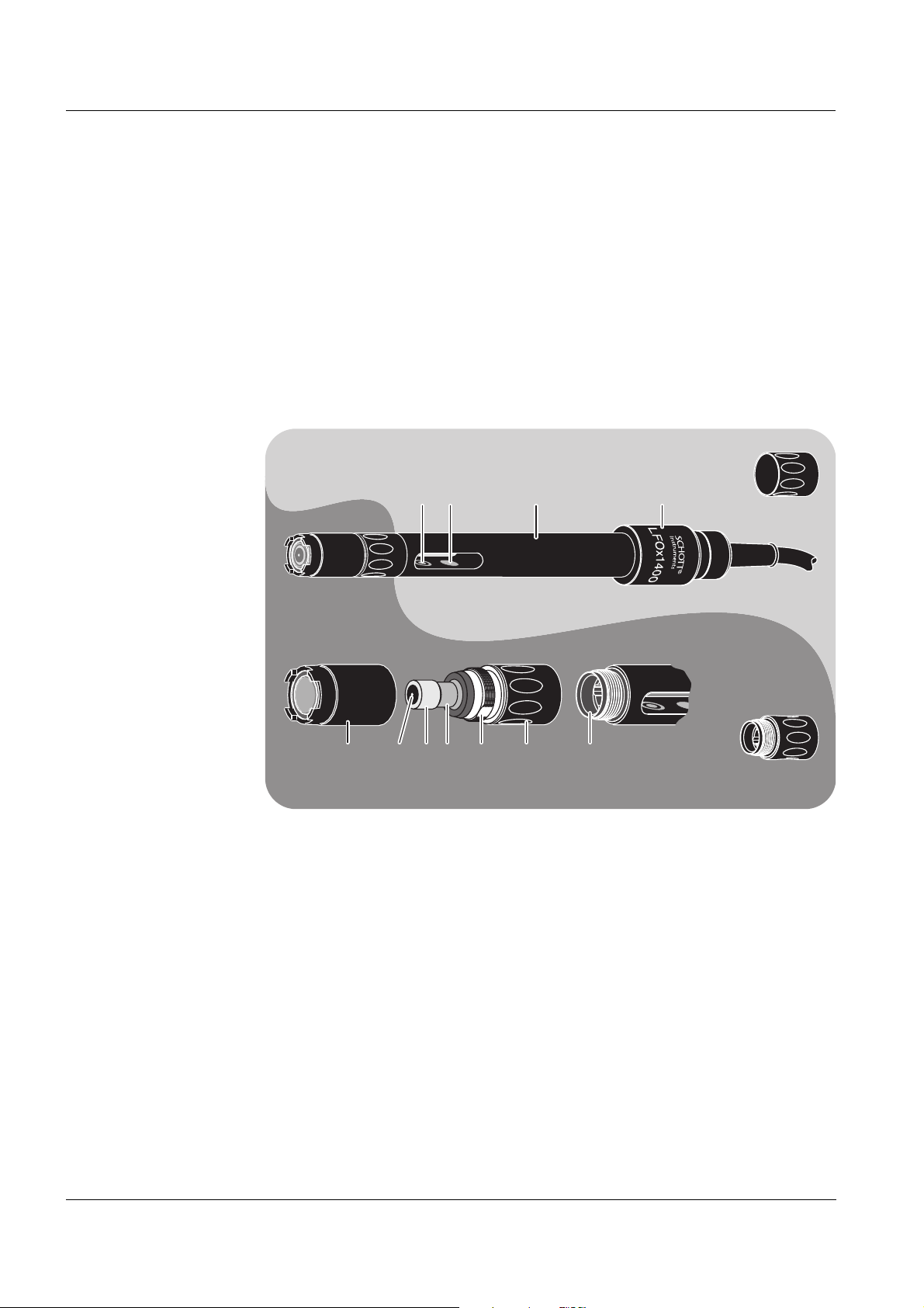
1.1 Structure and function
The LFOx1400(-ID) is a modular sensor for conductivity, dissolved oxygen
(DO) and temperature. It consists of two basic components:
Conductivity basic module, according to the quadripole measuring princi-
ple, with integrated temperature sensor
Removable dissolved oxygen module, according to the galvanic measur-
ing principle
Structure of the
LFOx1400(-ID)
1 Voltage electrode (inside, 2x)
2 Current electrode (ring, 2x)
3 Temperature sensor in a graphite enclosure
4 Shaft
28
5 Connection head
6 Membrane cap (filled with electrolyte solution)
7 Gold working electrode (cathode)
8 Insulator
9 Lead counter electrode (anode)
10 Screw thread base with ventilation area
11 Cap nut
12 Plug connection
13 Closing cap for conductivity basic module
14 Closing cap for DO module
ba75523e04 07/2011
LFOx1400(-ID) Overview
03360013
12 3
0342A007
1234
The conductivity basic module can be used as an independent conductivity
measuring cell. For this purpose, unscrew the DO module and close the open
plug connection with a closing cap.
The DO module is connected to the conductivity basic module via a watertight, three-pole plug connection. The conductivity basic module measures
the temperature, which is required for the determination of the DO content.
For this reason the DO module only works in conjunction with the conductivity
basic module.
Automatic sensor
recognition
Recommended
fields of
application
In the plug connector of the LFOx1400-ID sensor, data is stored for the automatic sensor recognition function. Among other, this data includes the sensor
type and series number. Besides, the calibration data is written in the sensor
with every calibration procedure. When the sensor is connected, the data is
called up by the meter and used for measurement and measured value documentation. The correct data is always used automatically if the sensor is operated with several meters because the data is stored in the sensor.
To be able to use the automatic sensor recognition function, a meter is
required that supports the function. More information on the automatic sensor
recognition function is given in the operating manual of the meter.
On site measurements in rivers, lakes and wastewater
Ground water measurements
Applications in water laboratories
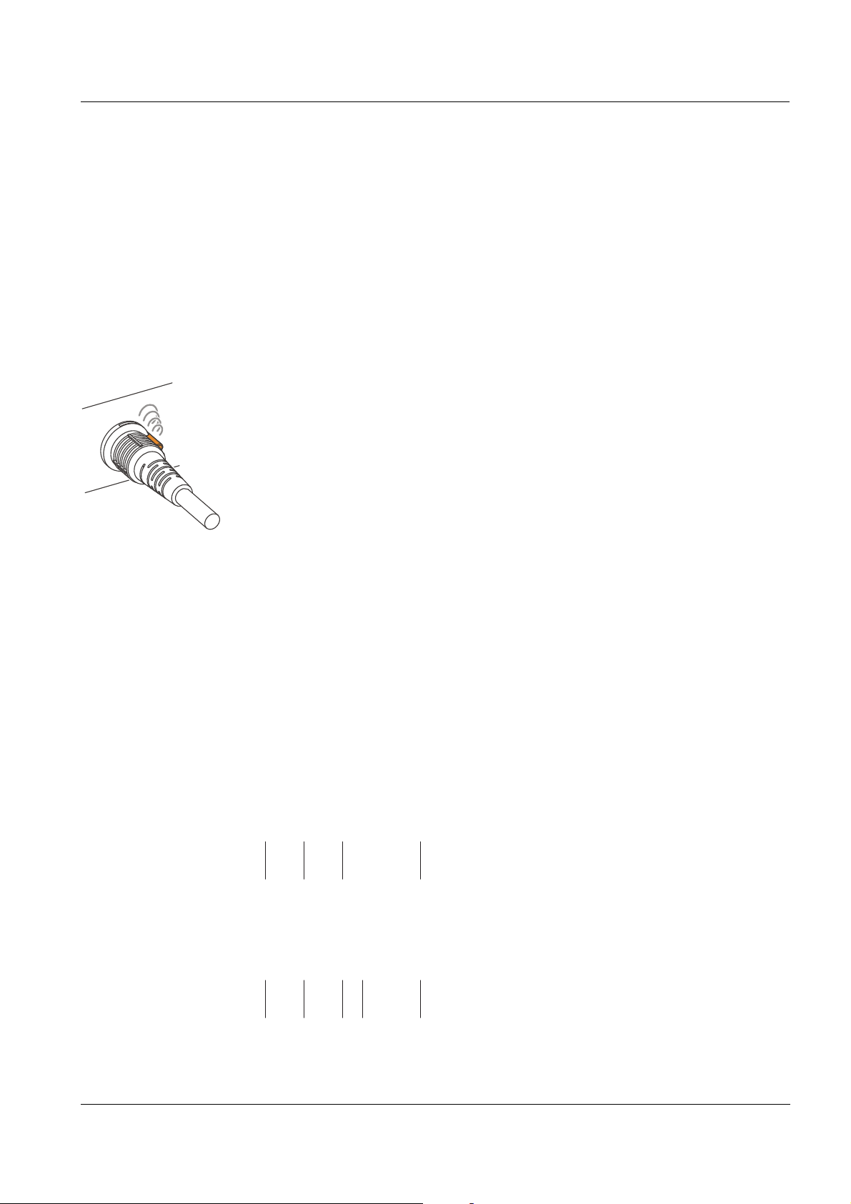
1.2 Instrument identification
A series number is printed on both LFOx1400(-ID) modules. Keep these
numbers ready if you have questions to ask the SI Analytics service
department. The series numbers contain the following information:
Conductivity basic
Dissolved oxygen
(DO) module
ba75523e04 07/2011
The number is printed on the shaft.
module
1 Manufacturing year 20... (example: 2003)
2 Calendar week of manufacturing (CW 36)
3 Sequential batch number (0013)
The number is printed on the cap nut.
1 Manufacturing year 20... (example: 2003)
2 Calendar week of manufacturing (CW 42)
3 Sensor type (type A)
4 Sequential batch number (007)
29
Safety LFOx1400(-ID)
2 Safety
This operating manual contains special instructions that must be followed
during the operation of the sensor.
Always keep this operating manual in the vicinity of the sensor.
Special user
qualifications
General safety
instructions
The membrane cap of the DO module is filled with a small amount of an
alkaline electrolyte solution. All maintenance work that requires dealing with
the electrolyte solution must only be carried out by persons who know how to
deal with chemicals safely.
The individual chapters of this operating manual use safety labels like the one
below to indicate danger:
Caution
indicates instructions that must be followed precisely in order to avoid
slight injuries or damage to the instrument or the environment.
3 Commissioning
3.1 Scopes of delivery
3.1.1 Scope of delivery of the LFOx1400(-ID)
LFOx1400(-ID) combination conductivity and DO sensor,
DO module filled with electrolyte solution and ready to use
1 closing cap for conductivity basic module
30
1 closing cap for DO module
3 exchange membrane caps, Ox923
Calibration and storage vessel, OxiCal
Polishing strip, SF300
Electrolyte solution, Ox920
Cleaning solution, Ox921
Operating manual for LFOx1400(-ID)
Note
The membrane cap that is mounted on the DO sensor for delivery serves
mainly as a transport protection. Depending on the duration of the transport
and storage period, it may have a shortened operational lifetime. If the measuring system cannot be calibrated (error message on the instrument),
please proceed according to section section 5.3 DO
ELECTROLYTE SOLUTION AND MEMBRANE CAP.
®
-CX
MODULE: CHANGING THE
ba75523e04 07/2011
LFOx1400(-ID) Commissioning
3.1.2 Scope of delivery of the conductivity basic module
Conductivity basic module
1 closing cap, mounted on the conductivity basic module
Operating manual for LFOx1400(-ID)
3.1.3 Scope of delivery of the DO module
DO module, filled with electrolyte solution and operable
1 closing cap, mounted on the DO module
1 exchange membrane cap, Ox923
Polishing strip, SF300
Electrolyte solution, Ox920
Cleaning solution, Ox921
Operating manual for LFOx1400(-ID)
Note
The membrane cap that is mounted on the DO sensor for delivery serves
mainly as a transport protection. Depending on the duration of the transport
and storage period, it may have a shortened operational lifetime. If the measuring system cannot be calibrated (error message on the instrument),
please proceed according to section section 5.3 DO
ELECTROLYTE SOLUTION AND MEMBRANE CAP.
MODULE: CHANGING THE
ba75523e04 07/2011
31
Commissioning LFOx1400(-ID)
12
21 3
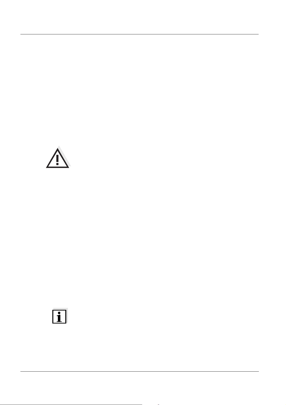
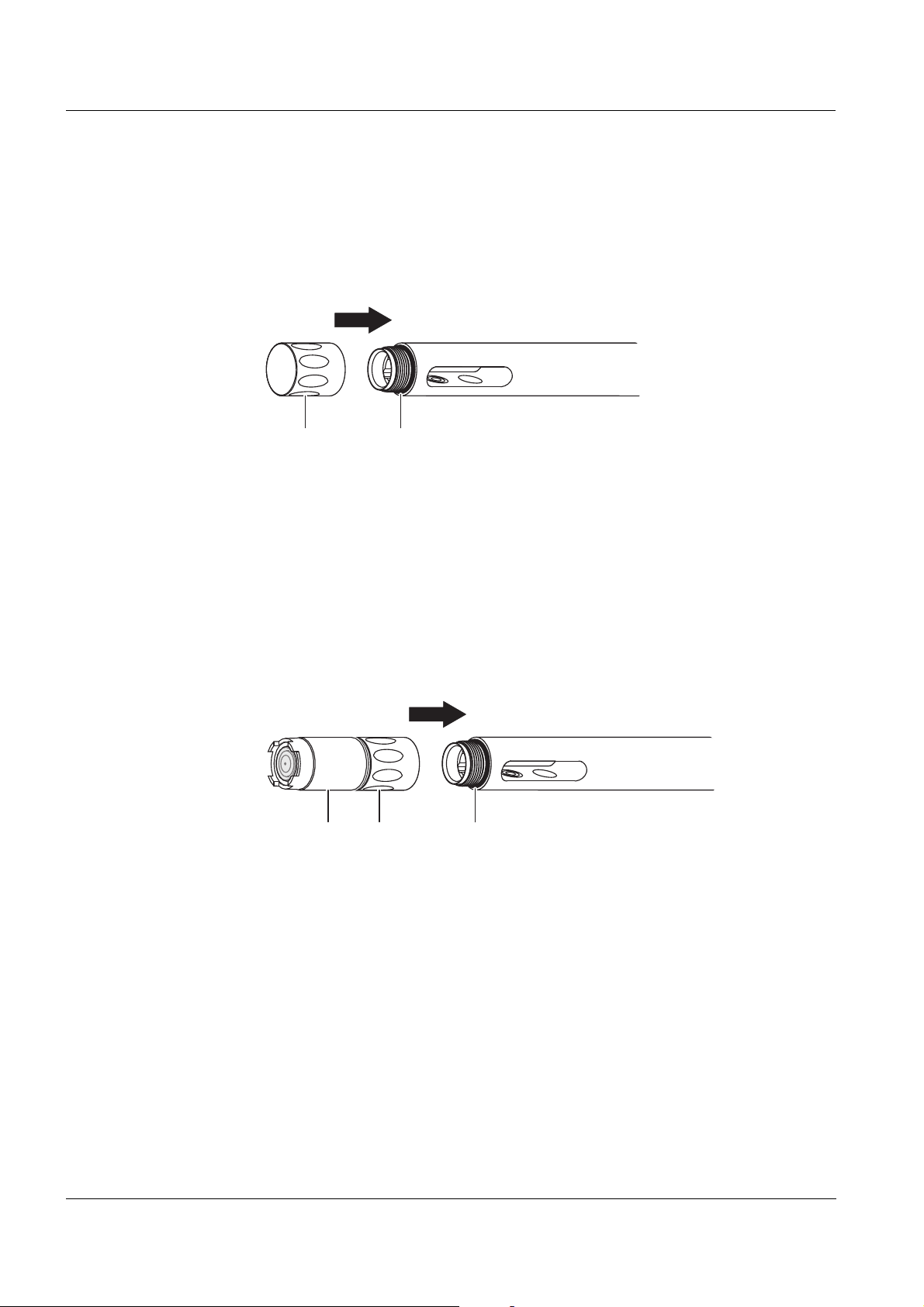
3.2 Getting the sensor ready for measuring
3.2.1 Measurements with the conductivity basic module
Make sure that the plug connection is tightly closed by the closing cap. When
mounted, the closing cap (1) must be screwed on up to the stop.
Before screwing on the closing cap, check the following points:
The sealing (2) must be clean and evenly positioned in the groove.
The plug connection and the inside of the closing cap must be clean.
Screwing on the
DO module
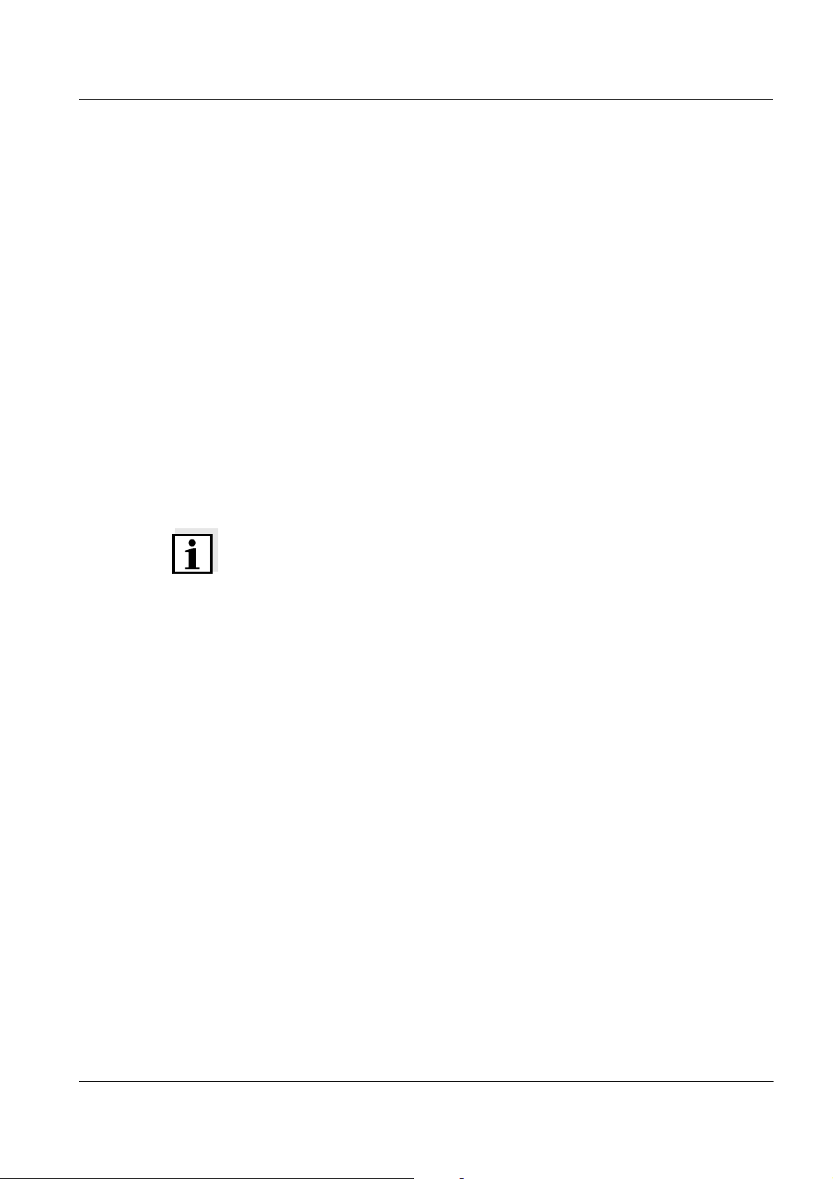
3.2.2 Measurements with the combination sensor
Make sure that the DO module and conductivity basic module are screwed
together tightly. When mounted, the cap nut of the DO module has to be
screwed on up to the stop.
Before screwing on the DO module, check the following points:
The sealing (3) must be clean and evenly positioned in the groove.
The plug connection must be dry on both sides.
Position the DO module (1) on the conductivity basic module and carefully
and with slight pressure turn it until the guiding nib on the DO module locks
in place in the corresponding groove on the conductivity basic module.
Subsequently tighten the cap nut (2) up to the stop. The thread only snatches
if the DO module was correctly positioned.
32
ba75523e04 07/2011

LFOx1400(-ID) Measuring / Operation
Unscrewing the
DO module
Unscrew the cap nut and remove the DO module from the conductivity basic
module.
Caution
Inappropriate handling can lead to the release of electrolyte solution.
When unscrewing the DO module only turn the cap nut (not the
membrane cap!).
3.2.3 Preparing the measuring operation
Connect the sensor to the measuring instrument. The sensor is immediately
ready to measure. It is not necessary to polarize the DO module.
4 Measuring / Operation
4.1 Calibration
To calibrate for DO measurements, use the OxiCal®-CX calibration and
storage vessel. If the A 325/K or A 325/S armoring is used, you have to
remove the protective hood and fixing nut of the armoring first.
Minimum
approach flow for
DO measurements
When determining the cell constant, observe the respective minimum
immersion depth with the closing cap or D. O. module screwed on (important:
the temperature sensor must be submersed). The minimum immersion
depths are given in chapter 7 T
ECHNICAL DATA.
Note
Please read the course of the calibration in the operating manual of the measuring instrument.
4.2 Measuring
Please always observe the required minimum immersion depth and the
minimum approach flow that is important for DO measurements (see
chapter 7 T
The minimum flow can be provided in different ways, e. g.:
The flow of the water to be measured is sufficient (aeration tank, water
pipe, stream)
Slowly pull the sensor through the water by hand (lake, container), or
Use a flow aid, e. g. a magnetic stirrer with stirring device or a battery stir-
rer (see chapter 8 W
ECHNICAL DATA).
EAR PARTS AND ACCESSORIES)
ba75523e04 07/2011
Note
When using the BR 325 battery stirrer, please make sure that the protective
pipe already has the groove in the area of the conductivity basic module (from
the year of manufacture, 2004).
33

Maintenance, cleaning, replacement LFOx1400(-ID)
12
4.3 Storage
Always store the sensor with the DO module in the calibration vessel at a
temperature of 0 to +50 °C. Make sure that the sponge in the calibration vessel is always moist.
Storage in the
calibration vessel,
OxiCal
®
-CX
Moisten the sponge:
Remove the cap (1).
Take out the sponge (2), wet it, then slightly squeeze it out.
Reinsert the sponge and close the calibration vessel with the cap.
5 Maintenance, cleaning, replacement
5.1 General maintenance instructions
For your safety Note the following safety instructions when handling electrolyte and cleaning
solutions:
Caution
The Ox920 electrolyte solution irritates eyes and skin. When dealing
with the Ox920 electrolyte solution, observe the following points:
During working activities, always wear suitable protective gloves
and protective goggles/face shield.
If it comes into contact with the skin, rinse thoroughly with water and
immediately change contaminated clothing.
If it comes into contact with the eyes, rinse thoroughly with water
and consult a doctor.
Follow the safety datasheet.
34
ba75523e04 07/2011

LFOx1400(-ID) Maintenance, cleaning, replacement
Caution
The Ox921 cleaning solution irritates eyes and skin. When dealing with
the Ox921 cleaning solution, observe the following points:
During working activities, always wear suitable protective gloves
and protective goggles/face shield.
If it comes into contact with the skin, rinse thoroughly with water and
immediately change contaminated clothing.
If it comes into contact with the eyes, rinse thoroughly with water
and consult a doctor.
Follow the safety datasheet.
Caution
Before all maintenance activities, disconnect the sensor from the
instrument.
Note
Information on how to order wear parts and maintenance means can be
found in chapter 8 W
EAR PARTS AND ACCESSORIES.
Maintenance
activities on the
DO module
Cleaning agents
For better handling, leave the DO module screwed on the conductivity basic
module. Thus, you can better immerse the sensor head in the electrolyte or
cleaning solution and the plug connection remains protected against
damage.
5.2 Outside cleaning
Contamination Cleaning procedure
Lime sediments Immerse in acetic acid for 1 minute (volume
share = 20 %)
Fat/oil Clean with warm water that contains
washing-up liquid
After cleaning, thoroughly rinse with deionized water and recalibrate if
necessary.
ba75523e04 07/2011
35

Maintenance, cleaning, replacement LFOx1400(-ID)
5.3 DO module: Changing the electrolyte solution and
membrane cap
Caution
Before starting to work with the sensor, please note the GENERAL
MAINTENANCE INSTRUCTIONS on page 34.
General
information
SI Analytics delivers the DO module ready to use (see section 3). The electrolyte solution and the membrane cap must only be replaced if:
a calibration error occurs and the membrane is heavily contaminated
the membrane is damaged
the electrolyte solution is exhausted.
36
ba75523e04 07/2011

LFOx1400(-ID) Maintenance, cleaning, replacement
Ox921
H O
2
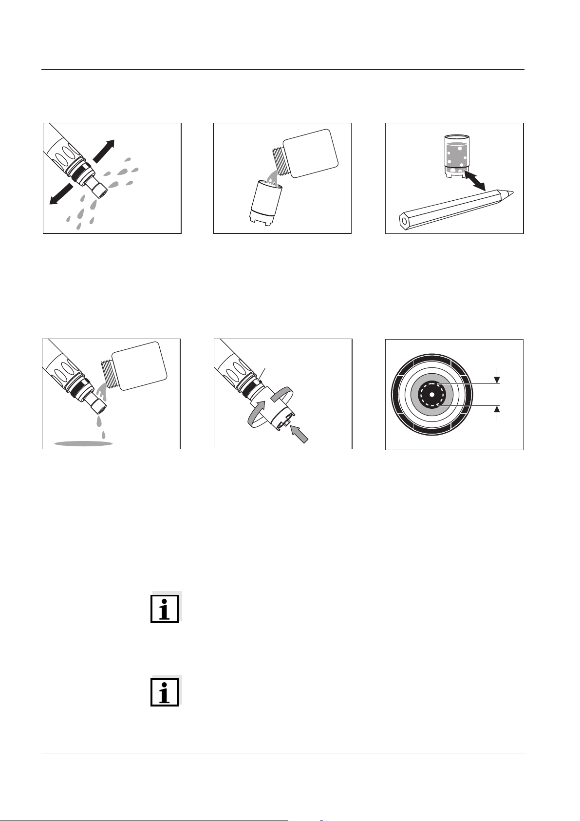
Changing the electrolyte solution and membrane cap
Unscrew the membrane cap.
Caution:
Electrolyte solution!
For disposal of the membrane
cap and electrolyte solution,
see section 5.7.
Immerse the sensor head including the counter electrode
in Ox921 cleaning solution.
Allow to react for 1 to 3 minutes.
Rinse the sensor head with
deionized water.
Thoroughly rinse the sensor
head with deionized water.
Carefully rub and dry the
counter electrode with a lintfree paper towel.
Water the counter electrode in
deionized water for at least
10 minutes.
ba75523e04 07/2011
37
Maintenance, cleaning, replacement LFOx1400(-ID)
Ox920
Ox920
Ventilation area
points upwards
4mm
Carefully shake off the drops
of water.
Thoroughly rinse the sensor
head with electrolyte solution.
Fill a new membrane cap with
Ox920 electrolyte solution.
Hold the sensor inclined and
screw on the membrane cap
fingertight using a paper towel. Excess electrolyte solution
is forced out of the ventilation
area.
Remove any air bubbles by
carefully tapping the membrane cap. Additionally, you
can prevent air bubbles by
throwing the first filling away
and refilling the membrane
cap.
Check the filling:
Inspect the face surface. No
air bubbles may be present
within the dashed circle. Air
bubbles outside this area do
not interfere.
Note
For measurements under high pressure the filling must be completely free of air bubbles.
Readiness to measure The DO module is ready for operation after approx. 30 to 50 min-
utes. Subsequently calibrate the sensor for DO measurements.
Note
If you want to measure very low DO concentrations (< 0.5 % saturation), we recommend to let the sensor rest overnight and then
calibrate it.
38
ba75523e04 07/2011

LFOx1400(-ID) Maintenance, cleaning, replacement
SF300
Ox921
5.4 DO module: Cleaning the electrodes
Caution
Before starting to work with the sensor, please note the GENERAL
MAINTENANCE INSTRUCTIONS on page 34.
General
information
Cleaning is only required in cases of slopes too small or too large (sensor
cannot be calibrated) that cannot be resolved by changing the membrane cap
and electrolyte solution.
Cleaning the electrodes
Unscrew the membrane cap.
Caution:
Electrolyte solution!
For disposal of the membrane
cap and electrolyte solution,
see section 5.7.
Rinse the sensor head with
deionized water.
Using the rough side of the
wet SF300 polishing strip,
polish off any contamination
from the gold working electrode using light pressure.
Caution:
Do not use any conventional sandpaper or glassfiber brushes.
Rinse the sensor head with
deionized water.
ba75523e04 07/2011
Wipe the counter electrode
with a lint-free paper towel
and carefully remove any
loose white deposits.
Immerse the sensor head including the counter electrode
in Ox921 cleaning solution.
Allow to react for 1 to 3 minutes.
39

Maintenance, cleaning, replacement LFOx1400(-ID)
H O
2
Ox920
Ox920
Ventilation area
points upwards
4mm
Thoroughly rinse the sensor
head with deionized water.
Fill a new membrane cap with
Ox920 electrolyte solution.
Water the counter electrode in
deionized water for at least
10 minutes.
Remove any air bubbles by
carefully tapping the membrane cap. Additionally, you
can prevent air bubbles by
throwing the first filling away
and refilling the membrane
cap.
Carefully shake off the drops
of water.
Rinse the sensor head with
electrolyte solution.
Hold the sensor inclined and
screw on the membrane cap
fingertight using a paper towel. Excess electrolyte solution
is forced out of the ventilation
area.
40
Check the filling:
Inspect the face surface. No
air bubbles may be present
within the dashed circle. Air
bubbles outside this area do
not interfere.
ba75523e04 07/2011

LFOx1400(-ID) Maintenance, cleaning, replacement
Note
For measurements under high pressure the filling must be completely free of
air bubbles.
Readiness to
measure
After approx. 30 to 50 minutes, the sensor is ready for operation. Subsequently calibrate the sensor.
Note
If you want to measure very low DO concentrations (< 0.5 % saturation), we
recommend to let the sensor rest overnight and then calibrate it.
5.5 Checking the DO module for freedom from zero-current
The DO module is free from zero-current. Checking the module for freedom
from zero-current is only necessary in the case of malfunctions that cannot
be remedied by exchanging the electrolyte solution and membrane cap or by
cleaning the electrodes.
There are two possibilities to check the DO module for freedom from zerocurrent:
Measurement in a nitrogen atmosphere (recommended method)
Measurement in a sodium sulfite solution according to DIN EN 25814/
ISO 5814.
Caution
If you check the sensor according to DIN EN 25814/ISO 5814, do not
leave the sensor in the sodium sulfite solution for more than 2 minutes.
Danger of sensor poisoning!
Test criterion The DO module is OK if the measuring instrument displays < 1 % DO
saturation after 2 minutes.
5.6 Aging of the conductivity measuring cell
Normally, the conductivity measuring cell does not age. Special measuring
media (e.g. strong acids and lyes, organic solvents) or too high temperatures
shorten the operational lifetime considerably or damage the measuring cell.
The warranty does not cover cases where such conditions cause failure or
mechanical damage.
ba75523e04 07/2011
41

Maintenance, cleaning, replacement LFOx1400(-ID)
5.7 Disposal
Caution
The Ox920 electrolyte solution irritates eyes and skin. When dealing
with the Ox920 electrolyte solution, observe the following points:
During working activities, always wear suitable protective gloves
and protective goggles/face shield.
If it comes into contact with the skin, rinse thoroughly with water and
immediately change contaminated clothing.
If it comes into contact with the eyes, rinse thoroughly with water
and consult a doctor.
Follow the safety datasheet.
Conductivity basic
module, DO
module and
membrane cap
Electrolyte
solution
For disposal, unscrew the membrane cap from the DO module. Then rinse
the entire sensor and the membrane cap with water.
We recommend to dispose of the conductivity basic module and the DO
module without membrane cap as electronic waste. The membrane cap may
be disposed of with the household refuse.
Disposal according to the safety data sheet.
42
ba75523e04 07/2011

LFOx1400(-ID) What to do if...
6 What to do if...
6.1 Error symptoms of DO measurement
Error symptom Cause Remedy
The sensor is in the air
and the display shows
0.0 mg/l or 0 % O
2
The sensor cannot be
calibrated
The sensor still cannot
be calibrated after
changing the electrolyte
and membrane cap
Incorrect temperature
display
Mechanical damage to
the sensor
– No connection between
measuring instrument and sensor
– Cable defective
– No electrolyte in the membrane
cap
– Contaminated membrane cap
– Electrolyte depleted
– Contaminated electrodes or
sensor toxification
– membrane cap not screwed on
tight enough
– The temperature sensor of the
conductivity basic module was not
immersed deep enough in the
measuring solution
– Temperature sensor defective
– Check connection between
measuring instrument and sensor
– Replace and refill the membrane
cap (see section 5.3)
– Replace and refill the membrane
cap (see section 5.3)
Subsequently, wait for 30 to
50 min and recalibrate.
– Clean the electrodes (see
section 5.4)
– Screw membrane cap tighter
– Observe the minimum immersion
depth
– Return the sensor
– Return the sensor
6.2 Error symptoms of conductivity measurement
Error symptom Cause Remedy
No temperature or conductivity display
Measurement delivers
implausible conductivity
values
Incorrect temperature
display
ba75523e04 07/2011
– No connection between
measuring instrument and sensor
– Cable defective
– Incorrect cell constant adjusted at
the measuring instrument
– Measuring range exceeded
– Contamination in the area of the
electrodes
– Electrodes damaged
– The temperature sensor was not
immersed deep enough in the
measuring solution
– Temperature sensor defective
– Check connection between
measuring instrument and sensor
– Check / correct the cell constant
– Observe the application range
– Clean the sensor (see
section 5.2).
– Return the sensor
– Observe the minimum immersion
depth
– Return the sensor
43

Technical data LFOx1400(-ID)
7 Technical data
7.1 Conductivity basic module
General features Measuring principle Four-electrode measurement
Cell constant 0.475 cm
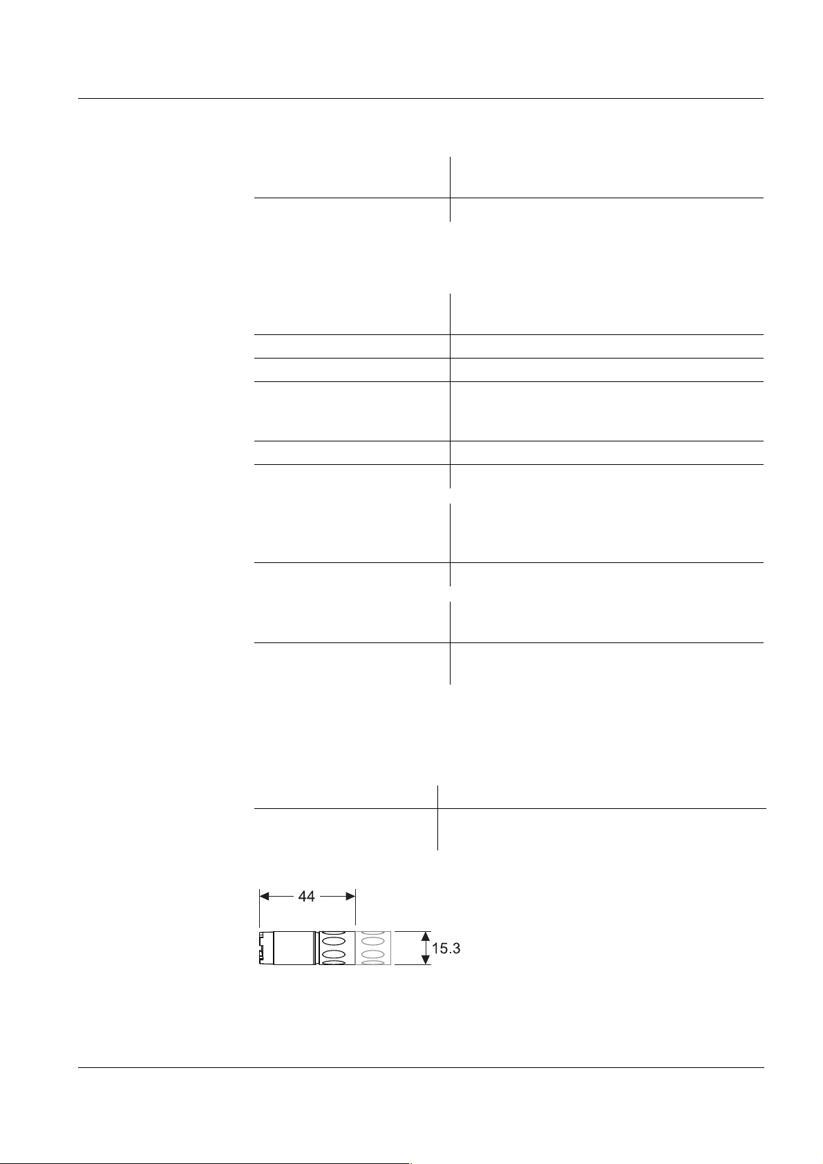
Temperature sensor integrated NTC 30 (30 k
Dimensions
(in mm)
-1
±1.5 %
Ω/ 25 °C)
Weight approx. 135 g (without DO module, with 1.5 m cable)
Materials Shaft Epoxy
– Connection head POM
– Closing cap PVC
Plug connection for
PEEK
DO module
Conductivity electrodes Graphite
Thermistor enclosure Graphite
Connection cable Lengths 1.5 / 3 / 6 / 10 / 15 / 20 m
Diameter 6 mm
Smallest allowed
bend radius
Fixed installation: 50 mm
Flexible use: 80 m
Plug type Socket, 8 pins
Connector for DO
module
Plug type 3-pole, watertight plug connection with cap
nut, reverse polarity protected, contacts
gold-plated
44
ba75523e04 07/2011
LFOx1400(-ID) Technical data
Pressure
resistance
Measurement
conditions
Storage
conditions
Sensor with closed plug
IP 68 (3 x 10⁵Pa or 3 bar)
connection
Cable plug IP 67 (when plugged in)
The LFOx1400(-ID) meets the requirements according to article 3(3) of the
97/23/EC directive ("Pressure equipment directive").
Conductivity measuring
1 µS/cm ... 2 S/cm
range
Temperature range 0 ... 50 °C
Max. allowed overpressure 3 x 10
5
Pa (3 bar)
Depth of immersion min. 6 cm (with closing cap)
min. 8 cm (with DO module)
max. 20 m (depending on the cable length)
Operating position any
Approach flow not required
Recommended storing
method
in the OxiCal
ened)
®
-CX calibration vessel (moist-
or dry (without DO module)
Storage temperature 0 ... 50 °C
Characteristic data
on delivery
Temperature responding
behavior
Precision of the temperature
(99 % of the final value display after)
t
99
<20s
±0.3K
sensor
7.2 Dissolved oxygen (DO) module
General features Measuring principle Membrane covered galvanic sensor
Temperature compensation
Dimensions
(in mm)
IMT compensation
(calculated by the measuring instrument)
Weight approx. 20 g (filled with electrolyte)
ba75523e04 07/2011
45

Technical data LFOx1400(-ID)
Materials Working electrode Gold
Counter electrode Lead
– Membrane cap
POM
– Cap nut
Membrane FEP, 13 µm
– Sensor head Epoxy, PEEK
– Plug connection PEEK
Screw thread base Stainless steel 1.4571
Seals FPM (Viton)
Closing cap POM
Plug connection Plug type 3-pole, watertight plug connection with cap nut,
reverse polarity protected, contacts gold-plated
5
Pressure
resistance
Sensor with closed plug
connection
IP 68 (3 x 10
Pa or 3 bar)
Measurement
conditions
Storage
conditions
The DO module meets the requirements according to article 3(3) of the 97/
23/EC directive ("Pressure equipment directive").
Measuring ranges at
20 °C
0 ... 50 mg/l DO
0 ... 600 % DO saturation
0 ... 1250 mbar DO partial pressure
Polarization time min. 30 ... 50 min after changing the electrolyte,
it is not necessary to connect the sensor to the
measuring instrument for polarization
Temperature range 0 ... 50 °C
Max. allowed overpres-
3 x 10
5
Pa (3 bar)
sure
Depth of immersion with
conductivity basic module
min. 8 cm
max. 20 m (depending on the cable length of
the conductivity basic module)
Operating position any
Approach flow > 3 cm/s at 10 % measurement accuracy
10 cm/s at 5 % measurement accuracy
18 cm/s at 1 % measurement accuracy
Recommended storing
method
in the OxiCal
ened)
®
-CX calibration vessel (moist-
Storage temperature 0 ... 50 °C
46
ba75523e04 07/2011

LFOx1400(-ID) Technical data
4
2
5
3
8
6
1
7
NTC
30 kΩ
Voltage electrode 2
Current electrode 1
Voltage electrode 1
Counter electrode
Working electrode
NTC
NTC
Current electrode 2
Conductivity basic moduleDO module
Shield
Shield+
wire
Plug from the front:
4
5
7
3
8
2
6
1
Plug connection:
GE
AE
Cod
GE GE
AE
Cod
AE
Characteristic data
on delivery
Pin assignment
Zero signal < 0.1 % of the saturation value
Response time at 20 °C t
Oxygen own consumption
(90 % of the final value display after) < 10 s
90
t
(95 % of the final value display after) < 16 s
95
(99 % of the final value display after) < 60 s
t
99
0.008 µg·h
-1
(mg/l)
-1
at 20 °C
Drift approx. 3 % per month in the operating condi-
tion
Working life min. 6 months with one electrolyte filling
ba75523e04 07/2011
47

Wear parts and accessories LFOx1400(-ID)
8 Wear parts and accessories
Wear parts and
maintenance
means
Description Model
Set of exchange membrane caps (3 pieces) Ox923/3
Electrolyte solution Ox920
Cleaning solution for lead counter electrode Ox921
Polishing film SF300
Accessory kit, comprising:
OX 925
– 3 exchange membrane caps, Ox923
– Polishing strip, SF300
– Electrolyte solution, Ox920
– Cleaning solution, Ox921
Note
For further accessories, refer to the SI Analytics catalog or the Internet.
48
ba75523e04 07/2011


SI Analytics GmbH
Postfach 2443
D-55014 Mainz
Hattenbergstr. 10
D-55122 Mainz
Telefon +49 (0) 61 31/66 5111
Telefax +49 (0) 61 31/66 5001
Email: support@
si-analytics.com
Internet: www.si-analytics.com
 Loading...