

Page 1

ITT
Vortex Series
Installation, Operation and Maintenance Instructions
IM205
Wastewater
Engineered for life
Page 2

2 Vortex Installation, Operation and Maintenance Manual
Page 3

Table of Contents
Table of Contents
Introduction and Safety ........................................................................................................................2
Technical Data ......................................................................................................................................7
General ............................................................................................................................................7
Components ..................................................................................................................................... 7
Start Up Procedures ..............................................................................................................................8
Delivery Check ................................................................................................................................. 4
Oil Level ..........................................................................................................................................8
Power Supply ................................................................................................................................... 8
Cable Entry ...................................................................................................................................... 8
Motor Protection..............................................................................................................................8
Motor Check ....................................................................................................................................8
Installation Parts ...............................................................................................................................9
Direction of Rotation ....................................................................................................................... 9
Current Check ..................................................................................................................................9
Start Frequency .............................................................................................................................. 10
Minimum and Maximum Submersible Depth ................................................................................. 10
Installation Options ............................................................................................................................ 11
Installation - Slide Rail ...................................................................................................................11
Check Point Installation ..................................................................................................................12
Installation - Hard Piped ................................................................................................................12
Routine Maintenance .......................................................................................................................... 14
General ..........................................................................................................................................14
Maintenance Schedule ....................................................................................................................14
Lubricants ......................................................................................................................................14
Cable Entry .................................................................................................................................... 14
Oil Level ........................................................................................................................................15
Oil Change .....................................................................................................................................15
Motor Housing ..............................................................................................................................15
Transportation and Storage .................................................................................................................16
Seal Fail and High Temperature ..........................................................................................................17
Seal Fail ..........................................................................................................................................17
High Temperature .......................................................................................................................... 17
Trouble Shooting ................................................................................................................................18
APPENDIX 1: Cable Connections ...................................................................................................... 20
Limited Warranty ................................................................................................................................ 22
Owners Information
Complete this information for your records. Model number and serial number may be found on the tag
mounted to the motor adapter.
Pump Model Number
Pump Serial Number
Control Model Number
___________________________________
Dealer
Dealer phone number
Date of purchase
Date of installation
Vortex Installation, Operation and Maintenance Manual 1
______________________
_______________________
____________________
______________________
__________________________
________________________
Page 4

Introduction and Safety
I. Introduction and Safety
Introduction
Foreward
We thank you for choosing an ITT pump, which will undoubtedly serve you both reliably
and economically for a long time, providing you observe the Maintenance instructions given
in this manual.
The Vortex pump is designed to pump sewage and other solids containing waste water.
Proper use and maintenance will prolong the operational life of your ITT pump. This
manual contains different warnings and safety instruction. Read this manual properly, so
that dangerous situations, physical injury or damage can be avoided. The pump is designed
for professional use only. Service and maintenance may only be done by authorized
personal, after reading this manual. The pump in basic version may not be used in a
potentially explosive atmosphere.
Description
This manual provides instructions for the Installation, Operation and Maintenance of the
Vortex pumps. This manual covers the standard product plus common options that are
available.
Requirement
Content
Key Topics
This manual must be read and understood before installation and start-up. ITT shall not be
liable for physical injury, damage or delays caused by a failure to observe the instructions for
installation, operation and maintenance contained in this manual.
This instruction manual covers several different pump models that all have similar power
end configurations. Most assembly, disassembly and inspection procedures are the same for
all the pumps. However, where there are differences, they are called out separately within
the manual. The design, materials and workmanship incorporated in the construction of
the pumps makes them capable of giving long, trouble free service. The life and satisfactory
service of any mechanical unit, however, is enhanced and extended by correct application,
proper installation, periodic inspection, condition monitoring and careful maintenance. This
instruction manual was prepared to assist operators in understanding the construction and
the correct methods of installing, operating and maintaining these pumps.
Technical Data
Start up Procedures
Installation Options
Routine Maintenance
Transportation and Storage
Seal Fail and High Temperature
Trouble Shooting
Cable Connections
2 Vortex Installation, Operation and Maintenance Manual
Page 5
Introduction and Safety (continued)
Safety
It is extremely important that you read, understand, and follow the safety messages and
regulations carefully before handling an ITT product. They are published to help prevent
• personal accidents and health problems
• damage to the product
• product malfunction
Observe all safety messages highlighted in other sections of this manual.
A pump is a pressure-containing device with rotating parts that can be dangerous.
Caution: You must observe the instructions for installation, operation, and maintenance contained in this manual. Failure to do so could result in physical injury,
damage, or delays.
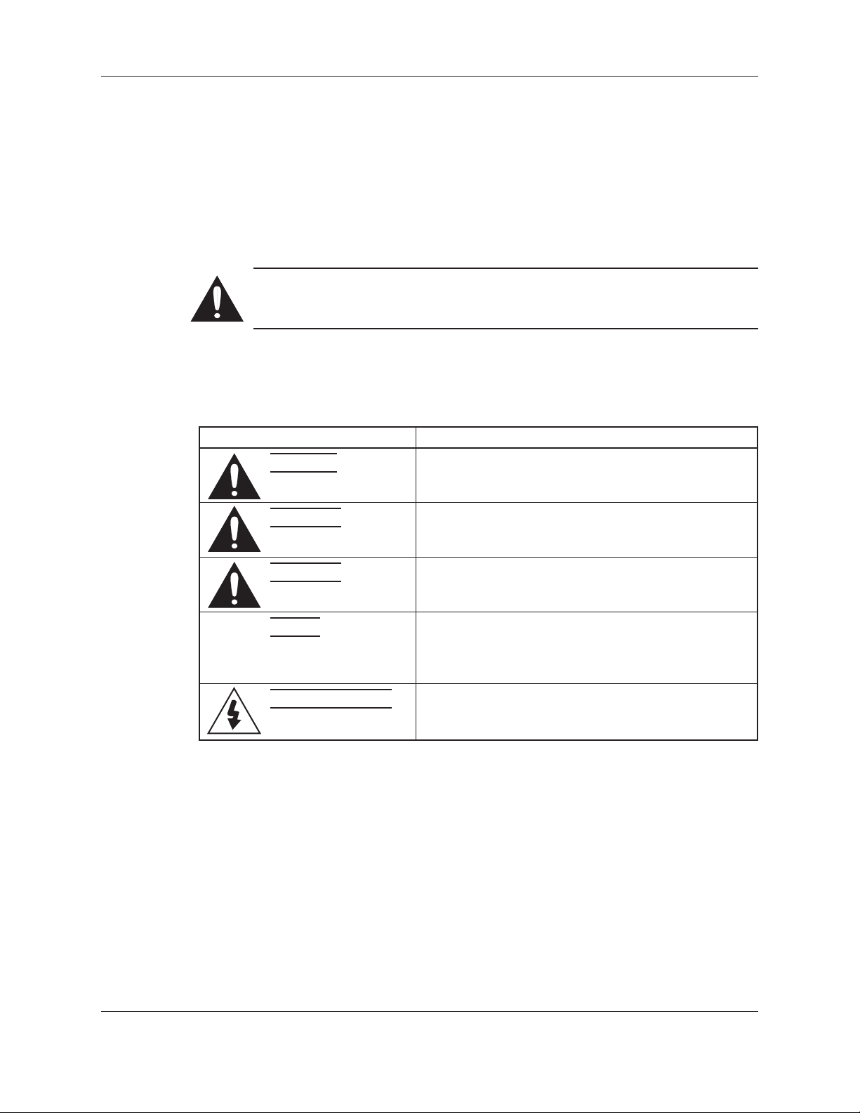
Safety message levels
Table 1: Definitions
Safety message level Indication
Danger: Indicates a hazardous situation which, if not
avoided, will result in death or serious injury.
Warning: Indicates a hazardous situation which, if not
avoided, could result in death or serious injury.
Caution: Indicates a hazardous situation which, if not
avoided, could result in minor or moderate injury.
Note: Indicates a potential situation which, if not avoided,
may result in undesirable results or state. Indicates a
practice not related to personal injury.
Electrical Hazard: Indicates the possibility of electrical risks if
direction are not applied in a proper manner.
Environmental safety
Preventive measures for the working area
Always keep the pump station clean to avoid and/or discover emissions.
Recycling guidelines
Always recycle according to the guidelines listed below:
1. Follow local laws and regulations regarding recycling if the unit or parts are accepted by
an authorized recycling company.
2. If the first guideline is not applicable then return the unit or parts to the nearest ITT
representative.
Vortex Installation, Operation and Maintenance Manual 3
Page 6

Introduction and Safety (continued)
Waste and emissions
Observe these safety regulations regarding waste and emissions:
• Dispose appropriately of all waste.
• Handle and dispose of the pumpage in compliance with applicable environmental
regulations.
• Clean-up all spills in accordance with safety and environmental procedures.
• Report all environmental emissions to the appropriate authorities.
Reference for electrical installation
For electrical installation recycling requirements, consult your local electric utility.
User health and safety
Safety equipment
Use safety equipment according to the company regulations. The following safety equipment should be used within the working area depending on the fluid being pumped:
• helmet
• safety goggles (with side shields)
• protective shoes
• protective gloves
• gas mask
• hearing protection
Note: The noise level of the product is lower than 70 dB. However, the
noise level of 70 dB may be exceeded in some installations and at certain
operating points on the performance curve. Make sure that you understand
the noise level requirements in the environment where the pump is installed. Failure to do so may result in hearing loss or violation of local laws.
The working area
Observe these regulations and warnings in the working area:
• Always keep the work area clean.
• Pay attention to the chemical and physical characteristics of the gas and vapors present
in hazardous areas.
• Avoid all electrical dangers. Pay attention to the risks of electric shock or arc ash hazards.
Product and product positioning requirements
Observe these requirements for the product and the product positioning:
• Never operate a pump unless safety devices are installed.
• Three-phase motors must have a properly sized starter with properly sized heaters
to provide overload and undervoltage protection. Single-phase motors have built-in
overload protectors.
• Never start a pump without the proper priming.
• Never run a pump below the minimum rated ow or with any suction or discharge
valve closed.
Electrical connections
Electrical connections must be made by authorized electricians in compliance with all international, national, state and local rules.
4 Vortex Installation, Operation and Maintenance Manual
Page 7

Observe the following regulations and warnings for electrical connections.
• Make sure that the product is isolated from the power supply and can not be
energized by mistake. This rule applies to the control circuit as well.
• Make sure that the thermal contacts are connected to a protection circuit according
to the product approvals, and that they are in use.
Observe the following regulations for grounding connections.
Table 2: Grounding
Grounding regulation Comment
All electric equipment must be grounded. This rule applies to pumps and mixers as
well as monitoring equipment.
Precautions before work
Observe the following safety precautions before working with or in connection with the
product:
• Make sure that there are no poisonous gases within the work area.
• Provide a suitable barrier around the work area, for example a guard rail.
• Make sure that all safety guards are in place and secure.
• Make sure that the equipment is properly insulated when operating at extreme tempera-
tures.
• Allow all system and pump components to cool before you handle them.
• Make sure that you have a clear path of retreat.
• Make sure that the product cannot roll or fall over and injure people or damage prop-
erty.
• Make sure that the lifting equipment is in good condition.
• Use a lifting harness, a safety line, and a breathing device as required.
• Make sure that the product has been thoroughly cleaned.
• Make sure that a rst-aid kit is close at hand.
• Check the explosion risk before welding or using electric hand tools.
Introduction and Safety (continued)
Precautions during work
Observe the following safety precautions when working with or in connection with the
product:
• Never work alone.
• Stay clear of suspended loads.
• Always lift the product by its lifting device.
• Beware of the risk of a sudden start if the product is used with an automatic level con-
trol.
• Beware of the starting jerk, which can be powerful.
• Rinse the components in water after disassembling the pump.
• Do not exceed the maximum working pressure of the pump.
• Do not open any vent or drain valves or remove any plugs while the system is
pressurized. Ensure that the pump is isolated from the system and that pressure is
relieved before you disassemble the pump, remove plugs, or disconnect piping.
Vortex Installation, Operation and Maintenance Manual 5
Page 8

Introduction and Safety (continued)
• Always bear in mind the risk of:
• electrical accidents
• burn injuries
Clean chemicals from the eyes
1. Forcibly hold the eyelids apart with the fingers.
2. Rinse the eyes for at least 15 minutes. Use an eyewash or running water.
3. Seek medical attention.
Clean chemicals from the body
1. Remove contaminated clothing.
2. Wash the skin with soap and water for at least 1 minute.
3. If required, seek medical attention.
Product approval standards
Regular standards
All electrical ratings and performance of the motors comply with UL, CSA and NEMA
standards.
Product warranty
Personnel requirements
All work on the product must be carried out by certified electricians and ITT authorized
mechanics.
ITT disclaims all responsibility for work done by untrained and unauthorized personnel.
Modification and spare parts
Modifications or changes to the product/installation should only be carried out after consulting with ITT. Original spare parts and accessories authorized by ITT are essential for
compliance. The use of other parts can invalidate any claims for warranty or compensation
and explosion-proof approvals.
Warranty claim
For warranty claim, contact your ITT Fluid Technology representative.
6 Vortex Installation, Operation and Maintenance Manual
Page 9

II. Technical Data
General
The vortex pump is a ductile/cast iron non-clogging vortex impeller pump, designed to
pump a wide variety of solids contaminated liquids.
The pump can be used for sewage and other non aggressive waste water applications.
The impeller leaves a wide unobstructed passage through the volute, in which a strong
vortex is created that carries most of the solids.
Components
5
Technical Data
9
7
6
9
11
15
2
4
1
Figure 1
14
13
8
12
10
3
1. Pump Casing 6. Rotor 11. Oil Reservoir
2. Impeller 7. Stator 12. Oil Plug
3. Suction 8. Shaft 13. Cable Entry
4. Discharge 9. Bearings 14. Cable
5. Motor Housing 10. Mechanical seal (2x) 15. Inspection Plug
Vortex Installation, Operation and Maintenance Manual 7
Page 10

Hazardous pressure can
cause personal injury or
property damage.
CAUTION
Start Up Procedures
III. Start Up Procedures
After unpacking the pump, carry out the following check points:
Delivery Check
Check for possible transport damage and especially check that the cable has not
been nicked or damaged.
Check for complete delivery.
When the delivery is incomplete or damaged, please contact your dealer
immediately.
Oil Level
Check the oil level (see Routine Maintenance section: Oil Level).
Power Supply
Before making the electrical connections, check if the line voltage and frequency are the
same as on the pump data plate.
For examples of electrical diagrams and pump cable coding, see appendix 1.
Cable Entry
Especially when the pump has been in storage for a long time, the cable gland should be
checked and if necessary tightened.
Motor Protection
The pump should always be connected to the line by means of a suitable motor protection
circuit breaker.
Overload protection must be provided in the panel.
Motor Check
If in doubt about the condition of the motor or cable, Megger test motor windings against
grounding wire.
The phase resistance against grounding wire should be at least 1 Mohm.
Figure 2
Turn the impeller clockwise by hand, using a proper socket wrench (see gure 6).
This should be possible without much force.
With this procedure sticking mechanical seal surfaces will be loosened smoothly.
8 Vortex Installation, Operation and Maintenance Manual
Page 11

Start Up Procedures (continued)
WARNING
Hazardous voltage
can shock, burn or
cause death.
Installation Parts
Check if all components for your installation are delivered.
Figure 3
Direction of Rotation
A correct direction of rotation is essential for proper operation. This can be checked as
follows:
• Put the pump in horizontal position and start the pump. Look at
impeller through the suction opening, the correct direction of rotation
is counterclockwise (see arrow on pump casing, Figure 3). or:
• Starting the pump will give a recoil on the pump frame. Looking at the
motor (in vertical position see Figure 4), the recoil is counterclockwise.
Take care! The recoil can be very powerful!
Don't go too near rotating parts!
Figure 4
Current Check
Note the maximum current from the data plate.
Apply an ammeter to one of the phase wires during normal operation. Check that the
current is not higher than the value on the data plate. If so check for:
• voltage (too low?) ± 5% nameplate
• specic gravity or viscosity of the uid
(too high?)
• blocked impeller?
• direction of rotation correct?
If the problem cannot be solved contact your dealer.
Vortex Installation, Operation and Maintenance Manual 9
Page 12

Hmin. 1
Hmin. 2
Start Up Procedures (continued)
Start Frequency
When the pump is controlled by level regulators, the on and off levels should be adjusted in
such a way, that the pump does not start more than 20 times an hour.
Minimum and Maximum Submersion Depth
The motor housing should be at least 2/3 submerged for continuous operation at full load
(see Hmin.1 Figure 5). It is good practice, whenever possible to keep the motor housing
completely under water.
For interrupted level controlled operation, less cooling is required. We recommend not to run
the pump with the water level below the top of the volute in order to avoid air being drawn in
(see Hmin.2 Figure 5).
Air in the discharge pipes might impair performance.
The maximum submersion depth is 20m/60ft.
Figure 5
10 Vortex Installation, Operation and Maintenance Manual
Page 13

IV. Installation Options
WARNING
Wire rope WILL FAIL if worn-out, overl oaded, misused,
damaged, improperly maintained or abused.
Wire rope failure may cause serious injury or death!
Protect yourself and others:
• ALWAYS INSPECT wire rope for, WEAR, DAMAGE or
ABUSE BEFORE USE.
• NEVER USE wire rope th at is WORN-OUT, DAMAGED
or ABUSED.
• NEVER OVERLOAD a wire rope.
• INFORM YOURSELF: Read and understand
manufacturer’s literature or “Wire Rope and Wire
Rope Sling Safety Bulletin”.*
• REFER TO APPLICABLE CODES, STANDARDS and
REGULATIONS for INSPECTION REQUIREMENTS and
REMOVAL CRITERIA.*
* For additional information or the BULLETIN, ask your
employer or wire rope supplier.
© 1993, Wire Rope Technical Board Form No. 193
For the submersible pump the following installations are possible:
• Slide rail installation
• Freestanding wet installation
Installation - Slide Rail
Stationary wet installation with a slide rail - The pump is automatically coupled to the
discharge.
Installation Options
Figure 6
Vortex Installation, Operation and Maintenance Manual 11
Except for the pump the following components are necessary:
1. Bottom elbow and pump adapter;
2. Guide bar foundation plate;
3. Two guide bars;
Page 14

1
10-15º
Installation Options (continued)
4. Top bracket, mounted within the wellcover clearance;
5. Switches for start-, stop-and alarm signals;
6. Suspension for switches and power supply cables;
7. Piping, non-return valve, discharge bends, etc.
Check points before operating:
• The guide bars must stand vertical (maximum tolerance 3°).
• The installation angle should be: 10-15º (see Figure 7). If necessary, this angle can be
changed by alteration of the position of the lifting hook on the suspension bracket on
top of the motor (pos. 1). (See bails in accessories.)
• Adjust the start-and stop levels in such a way that the motor does not make more then
20 starts per hour.
• Check that the motor is adequately cooled. The motorhousing should be at least 2/3
submerged for continuous operation at full load (see Hmin.1 Figure 6).
Figure 7
It is good practice, whenever possible, to keep the motor housing completely under water.
For interrupted level controlled operation, less cooling is required. We do not recommend
running the pump with a water level below the top of the volute, so as to avoid air being
drawn in.
Air in the discharge pipes will impair performance.
Check Point Installation
In some applications it is possible that the pump will not work due to presence of air in the
volute.
Lifting the pump a bit (10-20 mm) while running may solve the problem.
Installation - Hard Piped
Hard Piped: semi-permanent fixed wet installation.
Except for the pump the following components are necessary:
1. Pipe, which is fastened to the pump;
12 Vortex Installation, Operation and Maintenance Manual
Page 15

Hmin. 1
Hmin. 2
Installation Options
2. Pump support, stand, foot;
3. Switches.
Check points before operating:
• Adjust the start-and stoplevels in such a way that the motor does not make more than
20 starts per hour.
• Check that the motor is adequately cooled.
Figure 8
The motor housing should be at least 2/3 submerged for continuous operation at full load
(see Hmin.1 Figure 8).
Note: It is always good practice to drill 1/8" hole in the discharge pipe for venting air. This
will prevent the pump from air locking.
Vortex Installation, Operation and Maintenance Manual 13
Page 16

Hazardous pressure can
cause personal injury or
property damage.
CAUTION
1
2
3
WARNING
Hazardous voltage
can shock, burn or
cause death.
Routine Maintenance
IV. Routine Maintenance
General
Always disconnect the pump from the mains before inspection or
disassembly.
Clean the pump thoroughly.
The motor housing can be hot when the pump is just switched off.
Maintenance Schedule
Check oil once a year. If water is present oil will be milky in color.
Lubricants
• The bearings are greased for life and need no rell.
• The oil reservoir is lled with SHELL VITREA ISO-VG 46. Viscosity: 46 c St.
• Oil quantities: 20 oz.
Cable Entry
Especially when the pump has been in use for a long time, the compression of the rubber
cable seal might be diminished, which can cause leakage. By screwing in the cable entry the
seal will be retained.
Screw in the 2 hexagon socket screws (1).
Figure 9
14 Vortex Installation, Operation and Maintenance Manual
Page 17

Oil Level
Hazardous pressure can
cause personal injury or
property damage.
CAUTION
Hazardous pressure can
cause personal injury or
property damage.
CAUTION
21 2
A
1
B
21
C
1
2
Hazardous pressure can
cause personal injury or
property damage.
CAUTION
1
Hazardous pressure can
cause personal injury or
property damage.
CAUTION
Oil Change
Routine Maintenance (continued)
Put the pump in a horizontal position so that the 2 hexagonal socket screws
are on top and one at the bottom (see Figure 11). Unscrew the level plug
(1) and the vent plug (2).
The oil level should be at the lower side of the openings (see drawing). By
turning the pump a bit this should be visible. If not, fill up to the correct
level.
Always use the right kind of oil.
Collection, storage and removal of the oil should be done according to the
regulations of the local authorities.
Vortex Installation, Operation and Maintenance Manual 15
Motor Housing
Figure 10
When necessary replace the sealing rings.
Always use the right kind of oil. (See Figure 10).
Put the pump in a horizontal position so that one of the oil plugs is at the
bottom. Remove the vent plug (2). Put a receiving bin underneath the drain
plug (1). Remove the plug and drain the oil.
Rotate the pump so that the 2 openings are on top.
Refill the oil housing. The oil level should be at the lower side of the
openings. Replace the plugs.
Unscrew the inspection plug of the motor
housing. Put the pump in horizontal
position with the inspection opening
downwards. If water is present it will run
out this way. A small amount of water,
due to condensation is permissible. More
water is an indication of leakage of the
seal or housing. Oil is an indication of
seal failure between motorhousing and oil
chamber. Motor chamber is air filled only.
Figure 11
Page 18

Transportation and Storage
Hazardous pressure can
cause personal injury or
property damage.
CAUTION
WARNING
Wire rope WILL FAIL if worn-out, overloaded, misused,
damaged, improperly maintained or abused.
Wire rope failure may cause serious injury or death!
Protect yourself and others:
• ALWAYS INSPECT wire rope for, WEAR, DAMAGE or
ABUSE BEFORE USE.
• NEVER USE wire rope that is WORN-OUT, DAMAGED
or ABUSED.
• NEVER OVERLOAD a wire rope.
• INFORM YOURSELF: Read and understand
manufacturer’s literature or “Wire Rope and Wire
Rope Sling Safety Bulletin”.*
• REFER TO APPLICABLE CODES, STANDARDS and
REGULATIONS for INSPECTION REQUIREMENTS and
REMOVAL CRITERIA.*
* For additional information or the BULLETIN, ask your
employer or wire rope supplier.
© 1993, Wire Rope Technical Board Form No. 193
V. Transportation and Storage
The pump can be transported and stored in both horizontal and vertical
position.
Never lift the pump by the motor cable. Always use the lifting shackle.
In case of long storage, the pump must be protected against moisture and
heat.
Before storing the pump, clean
it with a water jet and check the
motor housing for water ingress
(see Motor Housing under Routine
Maintenance section). Every three
months, turn the impeller by hand.
This is necessary to prevent sticking
of the mechanical seal surfaces (see
Figure 12).
After 6 months of storage, a general
inspection is advised, before
installing the pump. Follow the
instructions of Section III: Start Up
Procedures.
Figure 12
16 Vortex Installation, Operation and Maintenance Manual
Page 19

Seal Fail and High Temperature
Hazardous pressure can
cause personal injury or
property damage.
CAUTION
VI. Seal Fail and High Temperature
Seal Fail
As a safeguard against water ingress into the motor, the pump is equipped with a water
detector.
The water detector detects water which might have entered the oil housing or motor
housing due to seal failure or cable damage.
The water detector, when connected to a seal fail circuit, alarms of water intrusion.
The probe itself is a non-active electrode, placed in oil and motor housing. It is used in
conjunction with a relay in the control circuit that measures the resistance between probe
and frame.
If only air or oil is present, the resistance is over 33,000 Ohm. If water enters, the resistance
will decrease to as low as 300 to 500 Ohm. We advise to use CentriPro seal fail relay. This
relay switches at 33,000 Ohms. See panel options in CentriPro catalog.
High Temperature
The pump is equipped with high temperature. The normal resistance of the
high temperature thermoswitch is 0-5 ohms. Leads on the cable (4 and 5
(see page 11)) should read "closed contact". Contacts will give open reading
in high temperature situation (125º – 140º C). High temperature will close
once motor temperature is normal (95º – 110º C).
Vortex Installation, Operation and Maintenance Manual 17
Page 20

Trouble Shooting
VII. Trouble Shooting
Safety
When working on the motor, make sure that the power is switched off. When working on
the pump make sure it cannot start unexpectedly. Only qualified electricians may do the
electrical work. When starting the pump ensure nobody goes near rotating parts.
PROBLEM POSSIBLE CAUSE REQUIRED ACTION CHECK POINTS
No voltage on Check power supply *No power
motor terminals *Main isolator switch
*Fuses
Check motor *Earth leakage relay
protection *Motor protection relay
Pump *Motor temperature
does not
start
stop signals *Obstructed level switches
*Switches interchanged
*Control panel
Motor failure Check motor *Continuity and isolation
wiring *Phase resistance
No stop signal Check level *Float switches
Pump regulation *Control panel
does not
stop
*Power supply not stable
Fault in power Check power *Low voltage
supply supply *Not all 3 phases available
Pump
starts and
stops
repeatedly
Motor overheated Check cooling *Continuity and isolation
Check motor *Fuses
Fault in power Check power *Low voltage
Current supply supply *Impeller blocked
too high
*Wrong direction of rotation
Clogging or air lock Check discharge *Discharge obstructed
and coupling *Valve fully or partly closed
*Air pocket in pump or discharge
Pump runs *Coupling leaks
but no flow or
too low flow
*Worn or broken impeller
Fault in power Check power *Control panel
supply supply *Fuses
*Low voltage
*Water detector
Check start and *Too low water level
Wrong start and Check level *Obstructed level switches
stop level regulation *Adjust start and stop level
*Setting of motor protection
Motor overloaded Check pump *Wrong direction of rotation
*Impeller blocked
*Protection in automatic reset mode
Pump failure Check pump *Visc. or spec. gravity too high
Pump failure Check pump *Impeller or volute blocked
*Pump is sucking to much air
18 Vortex Installation, Operation and Maintenance Manual
Page 21

Trouble Shooting (continued)
PROBLEM POSSIBLE CAUSE REQUIRED ACTION CHECK POINTS
Pump runs but Too low capacity Check discharge *Discharge obstructed
no flow or too *Valve fully or partly closed
low flow (cont.) *Air pocket
Pump failure Check pump *Impeller or volute blocked
*Pump is sucking to much air
High level
alarm
*Worn or broken impeller
*Worn or broken bearings
Fault in power Check *Fuses
supply power supply *Control panel
Motor failure Check motor *Continuity and isolation
Vortex Installation, Operation and Maintenance Manual 19
Page 22

1
o o o o
2 5G/Y
U V T
o
3
W
o
4
T
o
6
Wa
L1L2L
3
Appendix 1
VIII. Appendix 1: Cable Connections
PUMP CABLE CONNECTIONS
1 — Black – – – –> Motor
2 — White – – – –> Motor
3 — Red – – – –> Motor (1Ø capacitors)
4 — Orange – – – –> High Temperature
5 — Blue – – – –> High Temperature
6 — Yellow – – – –> Seal Fail
7 — Green/Yellow – – – –> Ground
20 Vortex Installation, Operation and Maintenance Manual
Page 23

Notes
Notes
Vortex Installation, Operation and Maintenance Manual 21
Page 24

ITT
Wastewater
LIMITED WARRANTY
This warranty applies to all water systems pumps manufactured by ITT Corporation.
Any part or parts found to be defective within the warranty period shall be replaced at no charge to the dealer during the warranty period. The warranty
period shall exist for a period of twelve (12) months from date of installation or eighteen (18) months from date of manufacture, whichever period is
shorter.
A dealer who believes that a warranty claim exists must contact the authorized ITT Corporation distributor from whom the pump was purchased and
furnish complete details regarding the claim. The distributor is authorized to adjust any warranty claims utilizing the ITT Corporation Customer Service
Department.
The warranty excludes:
(a) Labor, transportation and related costs incurred by the dealer;
(b) Reinstallation costs of repaired equipment;
(c) Reinstallation costs of replacement equipment;
(d) Consequential damages of any kind; and,
(e) Reimbursement for loss caused by interruption of service.
For purposes of this warranty, the following terms have these definitions:
(1) “Distributor” means any individual, partnership, corporation, association, or other legal relationship that stands between ITT Corporation and the
dealer in purchases, consignments or contracts for sale of the subject pumps.
(2) “Dealer” means any individual, partnership, corporation, association, or other legal relationship which engages in the business of selling or leasing
pumps to customers.
(3) “Customer” means any entity who buys or leases the subject pumps from a dealer. The “customer” may mean an individual, partnership,
corporation, limited liability company, association or other legal entity which may engage in any type of business.
THIS WARRANTY EXTENDS TO THE DEALER ONLY.
The ITT Engineered Blocks Symbol are registered
trademarks and tradenames of ITT Corporation.
SPECIFICATIONS ARE SUBJECT TO CHANGE WITHOUT NOTICE.
IM205 Revision Number 1 March, 2009
Copyright (c) 2009 ITT Corporation
Engineered for life
 Loading...