

Page 1
ITT
Goulds Pumps
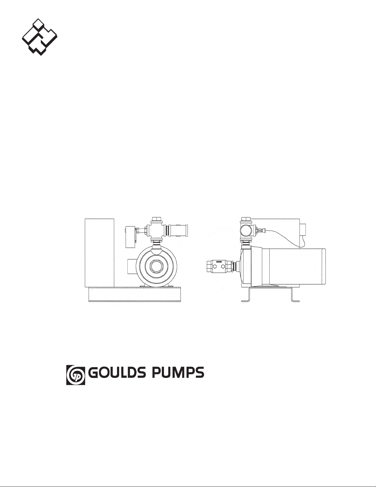
CentriBoost™
Fixed Speed Pumping Package
Installation, Operation and Maintenance Instructions
Commercial Water
Goulds Pumps is a brand of ITT
Residential and Commercial Water.
www.goulds.com
Engineered for life
Single or dual pump pressure booster for boosting system pressure by as much as
55 PSI. The pump is automatically controlled to run on demand to save energy.
Page 2

SECTION 1 - Safety Instructions . . . . . . . . . . . . . . . . . . . . . . . . . . . . . . . . . . . . . . . . . . . . . . . . . . . . . . . . . . . . 3
- General Description . . . . . . . . . . . . . . . . . . . . . . . . . . . . . . . . . . . . . . . . . . . . . . . . . . . . . . . . . . . 3
- Purpose of Manual. . . . . . . . . . . . . . . . . . . . . . . . . . . . . . . . . . . . . . . . . . . . . . . . . . . . . . . . . . . . 3
- Storage and Handling . . . . . . . . . . . . . . . . . . . . . . . . . . . . . . . . . . . . . . . . . . . . . . . . . . . . . . . . . 3
- Electrical Connections . . . . . . . . . . . . . . . . . . . . . . . . . . . . . . . . . . . . . . . . . . . . . . . . . . . . . . . . . 3
SECTION 2 - Installation . . . . . . . . . . . . . . . . . . . . . . . . . . . . . . . . . . . . . . . . . . . . . . . . . . . . . . . . . . . . . . . . . . 4
SECTION 3 - Putting the Unit into Service . . . . . . . . . . . . . . . . . . . . . . . . . . . . . . . . . . . . . . . . . . . . . . . . . . . . 5
- Adjustments and Settings . . . . . . . . . . . . . . . . . . . . . . . . . . . . . . . . . . . . . . . . . . . . . . . . . . . . . . 5
SECTION 4 Final Check Lists
- Start Up Check List - Piping . . . . . . . . . . . . . . . . . . . . . . . . . . . . . . . . . . . . . . . . . . . . . . . . . . . . . 6
- Start Up Check List - Electrical . . . . . . . . . . . . . . . . . . . . . . . . . . . . . . . . . . . . . . . . . . . . . . . . . . . 6
SECTION 5 Troubleshooting . . . . . . . . . . . . . . . . . . . . . . . . . . . . . . . . . . . . . . . . . . . . . . . . . . . . . . . . . . . . . . 6-7
APPENDIX 1 Programmable Pump Sequence Control Module for Duplex Units . . . . . . . . . . . . . . . . . . . . . . . . . . 8
FIELD PIPING . . . . . . . . . . . . . . . . . . . . . . . . . . . . . . . . . . . . . . . . . . . . . . . . . . . . . . . . . . . . . . . . . . . . . . . . . . . . .9
LIMITED WARRANTY . . . . . . . . . . . . . . . . . . . . . . . . . . . . . . . . . . . . . . . . . . . . . . . . . . . . . . . . . . . . . . . . . . . . . .12
NOTE: The information contained in this manual is intended to assist operating personnel by providing information on the
characteristics of the purchased equipment.
It does not relieve the user of the responsibility to adhere to local codes and ordinances and the use of accepted prac-
tices in the installation, operation and maintenance of this equipment.
Further information pertaining to the installation, operation and maintenance of your CentriBoost Pumping System can
be found in the Installation, Operation and Maintenance manuals for the associated equipment provided:
A. Goulds Pumps Model NPE
B. Tank (Model Specific)
Owner’s Information
Owner’s Information
Pump Model Number:
Pump Serial Number:
Control Model Number:
Dealer:
Dealer Phone No.
Date of Purchase: Installation:
Current Readings at Startup:
1Ø
Amps:
Volts:
2
Page 3
SECTION 1
dANGER
WARNING
CAUTION
WARNING
WARNING
WARNING
SAFETY INSTRUCTIONS
TO AVOID SERIOUS OR FATAL PERSONAL INJURY
OR MAJOR PROPERTY DAMAGE, READ AND
FOLLOW ALL SAFETY INSTRUCTIONS IN MANUAL
AND ON PUMP.
THIS MANUAL IS INTENDED TO ASSIST IN THE
INSTALLATION AND OPERATION OF THIS UNIT
AND MUST BE KEPT WITH THE PUMP.
This is a SAFETY ALERT SYMBOL.
When you see this symbol on the pump
or in the manual, look for one of the following signal words and be alert to the
potential for personal injury or property
damage.
Warns of hazards that WILL cause
serious personal injury, death or major
property damage.
Warns of hazards that CAN cause
serious personal injury, death or major
property damage.
Warns of hazards that CAN cause personal injury or property damage.
NOTICE: INDICATES SPECIAL INSTRUCTIONS
WHICH ARE VERY IMPORTANT AND
MUST BE FOLLOWED.
THOROUGHLY REVIEW ALL INSTRUCTIONS
AND WARNINGS PRIOR TO PERFORMING ANY
WORK ON THIS PUMP.
MAINTAIN ALL SAFETY DECALS.
GENERAl dESCRIpTION
The CentriBoost pumping package is a fixed constant
speed, and will increase the domestic water pressure
at the fixtures from 20 to 55 PSI above that of the city
water pressure.
Depending upon the pumping capacity required, a Simplex (one pump) type or a Duplex (two pump) type is
used. In both types, a pressure switch starts and stops the
pump(s).
TICES. FAILURE TO FOLLOW THESE INSTRUC-
TIONS COULD RESULT IN SERIOUS PERSONAL
INJURY, DEATH, AND/OR PROPERTY DAMAGE.
PREVENT ELECTRICAL SHOCKS.
DISCONNECT THE POWER SUPPLY
BEFORE BEGINNING INSTALLATION. FAILURE TO
FOLLOW THESE INSTRUCTIONS COULD RESULT
IN SERIOUS PERSONAL INJURY, DEATH AND/OR
PROPERTY DAMAGE.
Always use accurate test meters when checking electrical
components. Always work with another person in case of
emergency.
STORAGE
For long periods of storage, the unit should be covered to
prevent corrosion and contamination from dirt. It should
be STORED in a clean, dry location between 0 and 170°
F. The relative humidity should not exceed 85%. The
unit should be checked periodically to ensure that no
condensation has formed. After storage, again check that
it is dry before applying power.
HANdlING
Care should be taken to prevent damage due to dropping
or jolting when moving the CentriBoost. Transportation
damage should be brought to the carrier's attention immediately upon receipt.
TEmpERATURE ANd VENTIlATION
All electrical equipment is susceptible to failure if operated in ambient temperatures outside of its rating. The
OPERATING temperature range for this unit is 32 to
105° F. The relative humidity should not exceed 95%
non-condensing. The unit should not be operated outside
these extremes.
ElECTRICAl CONNECTIONS - A.C. pOWER
ANd SIGNAlS INpUT VOlTAGE
The input voltage tolerance is +10/-10% of nameplate
voltage.
pURpOSE OF mANUAl
This manual is furnished to acquaint you with some of
the practical ways to install, operate and maintain this
unit. Read it completely before doing any work on your
unit and keep it handy for future reference.
Equipment cannot operate well without proper care. To
keep this unit at top efficiency, follow the recommended
installation and servicing procedure outlined in this
manual.
AddITIONAl SAFETY REQUIREmENTS
ELECTRICAL SHOCK HAZARD.
INSPECT ALL ELECTRICAL CONNECTIONS PRIOR TO POWERING THE UNIT. WIRING
CONNECTIONS MUST BE MADE BY A QUALIFIED
ELECTRICIAN IN ACCORDANCE WITH ALL APPLICABLE CODES, ORDINANCES AND GOOD PRAC-
GROUNd CONNECTIONS
A grounding terminal is provided for a dedicated ground
wire connection. All provisions of the National Electrical
Code and local codes must be followed.
CONDUIT GROUNDS ARE NOT AD-
EQUATE. A SEPARATE GROUND WIRE
MUST BE ATTACHED TO THE GROUND LUG PROVIDED IN THE ENCLOSURE TO AVOID POTENTIAL
SAFETY HAZARDS. FAILURE TO FOLLOW THESE
INSTRUCTIONS COULD RESULT IN SERIOUS
PERSONAL INJURY, DEATH AND/OR PROPERTY
DAMAGE.
pOWER WIRING
Power wire types and sizes must be selected based upon
conformance with the National Electrical Code and all
local codes and restrictions. In addition, only copper
3
Page 4
(Cu) wire rated for at least 75° C may be used for the
dANGER
WARNING
WARNING
WARNING
CAUTION
power connections. Refer to the input current as listed
on the motor nameplate when sizing wire.
cut out. If the system does not include the other devices,
consult the responsible engineer or architect before making pumps operational.
FIEld CONNECTION dIAGRAmS
Refer to the NPE pump Installation, Operation and Maintenance manual for specific details unique to the pump.
The following field connection diagrams should be reviewed prior to unit installation and operation.
Drawing # Description Page
1MBD02 Piping: Simplex 8
1MBD03 Piping: Duplex 9
1SWD01 or Wiring, Simplex
1SWD02 (shipped with unit)
1SWD03 Wiring, Duplex
(shipped with unit)
1380
(shipped with unit)
_ _
Unit specific Drawing
SECTION 2
INSTAllATION INSTRUCTIONS
Locate the pumping unit for ease of inspection, maintenance, and service.
Place the unit preferably on a concrete floor or base.
Level the steel base, on which the pumps are mounted, in
both directions by placing steel shims between the base
and the anchor bolts.
HEAVY LOAD, MAY DROP IF NOT
LIFTED PROPERLY. DO NOT LIFT
THE ENTIRE UNIT BY THE MOTOR EYEBOLTS.
LIFT THE UNIT WITH SLINGS PLACED UNDER
THE UNIT BASE RAILS. FAILURE TO FOLLOW
THESE INSTRUCTIONS COULD RESULT IN SERIOUS PERSONAL INJURY, DEATH AND/OR PROPERTY DAMAGE.
A well-leveled and secured unit will result in quiet operation as well as longevity of service.
See drawing 1MBD02 (Simplex) or 1MBD03 (Duplex) in
Section 6 for general piping requirements.
Eccentric increasers can be used in the suction line when
increasing the pipe size. The straight side of eccentric
reducers should be installed with the flat side on top to
eliminate air pockets. Support the suction and discharge
lines independently by the use of pipe hangers or anchors. Do not attempt to spring the suction and discharge lines into position. It is recommended that a three
(3) valve by-pass between the suction and discharge be
installed at this time. See drawing 1MBD02 or 1MBD03
for location of valves.
IMPORTANT: Do not install and operate Goulds pumps
in closed systems unless the system is constructed with
properly sized safety devices and control devices. Such
devices include the use of properly sized and located
pressure relief valves, compression tanks, pressure
controls, temperature controls and flow controls as appropriate. The CentriBoost includes a high temperatures
4
THE HEATING OF WATER AND
OTHER FLUIDS CAUSES VOLUMETRIC EXPANSION. THE ASSOCIATED FORCES MAY
CAUSE FAILURE OF SYSTEM COMPONENTS AND
RELEASE OF HIGH TEMPERATURE FLUIDS. THIS
WILL BE PREVENTED BY INSTALLING PROPERLY
SIZED AND LOCATED PRESSURE RELIEF VALVES
AND COMPRESSION TANKS. FAILURE TO FOL-
LOW THESE INSTRUCTIONS COULD RESULT IN
SERIOUS PERSONAL INJURY, DEATH AND/OR
PROPERTY DAMAGE.
IMPORTANT: Unless the piping to which the vibra-
tion eliminators are connected to are properly anchored
to the floor, the benefits may not be fully realized. See
drawing 1MBD02 (Simplex) or 1MBD03 (Duplex).
ELECTRICAL SHOCK HAZARD.
INSPECT ALL ELECTRICAL CONNECTIONS PRIOR TO POWERING THE UNIT. WIRING
CONNECTIONS MUST BE MADE BY A QUALIFIED
ELECTRICIAN IN ACCORDANCE WITH ALL APPLICABLE CODES, ORDINANCES, AND GOOD PRACTICES. FAILURE TO FOLLOW THESE INSTRUC-
TIONS COULD RESULT IN SERIOUS PERSONAL
INJURY, DEATH, AND/OR PROPERTY DAMAGE.
The power supply required for the unit is either 230/1/60
or 208, 230, 460/3/60 with a dedicated ground wire.
Single phase motors have internal overload protection
and three phase motors have external overload protection in the control panel.
On single phase units the disconnecting means and short
circuit protection are to be supplied and mounted by
others. Three phase units have disconnecting means and
fuses for short circuit protection in the control panel.
For units installed with an optional tank, the tank must
be installed to the top connection of the discharge cross
for simplex units and the discharge manifold for duplex
units (see 1MBD02 or 1MBD03). Precharge the tank per
the tank specific IOM.
For units installed with an optional low suction pressure
switch, the switch, which typically ships loose, must be
piped to the inlet ¼" tap on the check valve for simplex
units or on of the ¼" tap on the suction manifold for duplex units (see 1MBD02 or 1MBD03). See section 3.10
for instructions on setting the switch.
CONDUIT GROUNDS ARE NOT AD-
EQUATE. A SEPARATE GROUND WIRE
MUST BE ATTACHED TO THE GROUND LUG PROVIDED IN THE ENCLOSURE TO AVOID POTENTIAL
SAFETY HAZARDS. FAILURE TO FOLLOW THESE
INSTRUCTIONS COULD RESULT IN SERIOUS
PERSONAL INJURY, DEATH AND/OR PROPERTY
DAMAGE.
SEAL DAMAGE MAY OCCUR. DO
NOT RUN PUMPS DRY. FILL AND
VENT THE PUMP VOLUTE PRIOR TO OPERATION.
FAILURE TO FOLLOW THESE INSTRUCTIONS
COULD RESULT IN PROPERTY DAMAGE AND/OR
MODERATE PERSONAL INJURY.
Page 5

CAUTION
WARNING
WARNING
SECTION 3
pUTTING THE UNIT INTO SERVICE
PREVENT SUBSEQUENT DAMAGE.
A UNIT SHOWING SYMPTOMS OF
POSSIBLE PROBLEMS (NOISE, LEAKS, VIBRATION,
AND/OR CONTINUAL OPERATION) MUST BE CORRECTED IMMEDIATELY. FAILURE TO FOLLOW
THESE INSTRUCTIONS COULD RESULT IN PROPERTY DAMAGE AND/OR MODERATE PERSONAL
INJURY.
Simplex package - for capacities up to 110 GPM.
Whenever the city water pressure falls below the system
pressure switch setting the pump will start through a
power relay.
When the system pressure rises above the setting of the
system pressure switch the pump will stop (provided the
minimum run timer has expired.)
Duplex package - for capacities up to 220 GPM.
The lead pump operates identically to the Simplex package. However, if the draw rate continues to increase beyond the capacity of the lead pump, the system pressure
will fall and cause Pump 2 On/Off pressure switch to trip
which in turn starts the lag pump.
Both pumps will continue to run until the system pressure rises above the setting of Pump 1 and Pump 2 pressure switches (provided the minimum run timers have
expired.)
For the duplex unit Pump 2 also acts as a Standby for
Pump 1. In the event there is a call for Pump 1 and it has
failed for whatever reason, Pump 2 will start and act as
the lead pump. Once Pump 1 is fixed, place the Pump 1
HOA into the Off/Reset position and then back to Auto
to reset the unit.
Simplex and Duplex units will run when there is demand
unless one of the following conditions occurs:
1) The optional low suction pressure switch trips due
to low city pressure
2) The high temperature cut out switch trips due to
the pump deadheading.
The low suction condition will reset automatically
when city pressure returns to an acceptable level.
If the unit cuts out on high temperature the unit can
reset automatically when there is demand by drawing
cooler water throughout the unit and across the temperature sensor. This will cool the sensor and cause
it to change state and restart the pump. A manual
purge can be done by running the unit in "Hand" for
about 5 seconds. The unit can then be put back into
"Auto" for normal operation.
AdJUSTmENTS ANd SETTINGS
Low Suction Pressure Switch (Optional)
ELECTRICAL SHOCK HAZARD.
SINGLE PHASE OR THREE PHASE AC
POWER. DISCONNECT AND LOCKOUT POWER
BEFORE SERVICING THE UNIT. FAILURE TO FOL-
LOW THESE INSTRUCTIONS COULD RESULT IN
SERIOUS PERSONAL INJURY, DEATH AND/OR
PROPERTY DAMAGE.
The pressure switch is piped into the suction line. There
is an adjusting dial located inside of the control. This
adjustment controls the low suction cutout.
The differential pressure setting is fixed at 1.5 PSI.
Therefore cut in pressure will be the switch setting plus
1.5 PSI.
Although the scale is calibrated in PSI, it may not correspond exactly to the actual suction gage indication.
Therefore, for critical installations, the setting should be
adjusted according to the gage reading.
The approximate settings should be set prior to placing
the unit in operation to suit the pressure conditions at
the installation.
System Pressure Switch (Simplex), Pump 1 and
Pump 2 Pressure Switch for Duplex
ELECTRICAL SHOCK HAZARD. DISCONNECT AND LOCKOUT POWER
BEFORE SERVICING THE UNIT. FAILURE TO FOL-
LOW THESE INSTRUCTIONS COULD RESULT IN
SERIOUS PERSONAL INJURY, DEATH AND/OR
PROPERTY DAMAGE.
This switch is piped to the discharge header piping.
There are two adjusting screws located on the top of the
control. Facing the switch, the screw on the right hand
side sets the cut-out point. This adjustment must be made
first.
The screw to the left and towards the front sets the cutin point. Turn the screw until the proper cut-in point is
obtained.
Although the scales are calibrated in PSI, they may not
correspond exactly to the actual discharge gage indication. Therefore, for critical installations, the settings
should be adjusted according to the gage reading. See
wiring diagram 1SWD04 for proper settings of the system pressure switches on a duplex unit.
Minimum Run Timer
For a simplex unit the minimum run timer is factory set
to 5 minutes. The setting should be verified before unit is
place into operation and adjusted if a shorter minimum
run time is desired. See Appendix 1 for instructions on
using the programmable pump sequence control module
to set the minimum run timers for a duplex unit. Appendix 1 also contains information about setting additional
parameters that are specific to duplex units.
Aquastat
The aquastat for high temperature cut out is factory set
for 100° F and should be adjusted if a different cut out
temperature is desired. The switch should not be set
above 225° F.
Optional Tank
Since a variety of different tanks can be used with either
the simplex or duplex units refer to the specific IOM that
was shipped with the tank for installation and operating
instructions.
5
Page 6

SECTION 4
CAUTION
WARNING
WARNING
WARNING
dANGER
INSTAllATION INSTRUCTIONS
A. SYSTEM PIPING AND UNIT INSTALLATION
_____ 1. Is the unit base properly leveled and
secured?
_____ 2. Are all lubrication points properly
lubricated?
_____ 3. Is the shut-off valve to the pump suction
open?
_____ 4. Is the shut-off valve on the discharge
line open?
_____ 5. Is the bypass valve, if used, closed?
_____ 6. Is the piping properly supported to
prevent strains on unit?
_____ 7. Is the system, including the pumps,
purged of debris and air?
ELECTRICAL SHOCK HAZARD.
SINGLE PHASE OR THREE PHASE AC
POWER. DISCONNECT AND LOCKOUT POWER
BEFORE SERVICING THE UNIT. FAILURE TO FOL-
LOW THESE INSTRUCTIONS COULD RESULT IN
SERIOUS PERSONAL INJURY, DEATH AND/OR
PROPERTY DAMAGE.
_____ 4. Are the pressure controls correctly set?
The pressure switch(es) need to be set
for proper operation. Any subsequent
change in system operating conditions
may require resetting the controls. For
best results, use compressed air and a
continuity meter (across the switch) to
reset the controls. The legend plate on
the control indicates approximate
readings only, therefore, should be used
with caution.
SECTION 5
TROUblESHOOTING
SEAL DAMAGE MAY OCCUR. DO
NOT RUN PUMPS DRY. FILL AND
VENT THE PUMP VOLUTE PRIOR TO OPERATION.
FAILURE TO FOLLOW THESE INSTRUCTIONS
COULD RESULT IN PROPERTY DAMAGE AND/OR
MODERATE PERSONAL INJURY.
B. ELECTRICAL WIRING AND CONTROL SETTINGS
_____ 1. Does the feeder line voltage correspond
to the unit voltage? Check the unit
nameplate or motor terminal
connection.
ELECTRICAL SHOCK HAZARD.
INSPECT ALL ELECTRICAL CONNECTIONS PRIOR TO POWERING THE UNIT. WIRING
CONNECTIONS MUST BE MADE BY A QUALIFIED
ELECTRICIAN IN ACCORDANCE WITH ALL APPLICABLE CODES, ORDINANCES, AND GOOD PRACTICES. FAILURE TO FOLLOW THESE INSTRUC-
TIONS COULD RESULT IN SERIOUS PERSONAL
INJURY, DEATH AND/OR PROPERTY DAMAGE.
_____ 2. Are the feeder wires correctly sized for
the load?
CONDUIT GROUNDS ARE NOT AD-
EQUATE. A SEPARATE GROUND WIRE
MUST BE ATTACHED TO THE GROUND LUG PROVIDED IN THE ENCLOSURE TO AVOID POTENTIAL
SAFETY HAZARDS. FAILURE TO FOLLOW THESE
INSTRUCTIONS COULD RESULT IN SERIOUS
PERSONAL INJURY, DEATH AND/OR PROPERTY
DAMAGE.
_____ 3. Have all the power terminals in the
control panel been checked for
tightness? This is imperative since
stranded wires tend to "flow" and
become loose after initial installation.
TROUBLESHOOTING LIVE CON-
TROL PANELS EXPOSES PERSONNEL TO HAZARDOUS VOLTAGES. ELECTRICAL
TROUBLESHOOTING MUST ONLY BE DONE BY A
QUALIFIED ELECTRICIAN. FAILURE TO FOLLOW
THESE INSTRUCTIONS WILL RESULT IN SERIOUS
PERSONAL INJURY, DEATH AND/OR PROPERTY
DAMAGE.
PUMP WILL NOT OPERATE:
1) Check incoming power
2) Check power fuses. Replace if blown.
3) Check transformer fuses. Replace if blown.
4) Check to see that control voltage is 120 volt.
5) Check motor overload. Reset if tripped.
6) Momentarily turn HOA switch to HAND position
and back to OFF. Does starter pull in? If starter
doesn’t pull into go to next step. If it does pull in
go to step 10.
7) Turn HOA switch to HAND position. Check voltage across terminals for coil in starter. If voltage
is present and the starter is not pulled in, the coil
is defective and must be replaced. If voltage isn’t
present go to step 8.
8) With HOA still in HAND, check voltage between
HOT side of starter coil and the neutral (white)
wire. 120 volts should be measured. If voltage is
measured go to step 9.
9) With HOA still in HAND, check voltage between
the hot side of coil & neutral (white wire) for
over load block. 120 volts should be measured. If
voltage is measured replace the overload block.
If no voltage is present contact your local Goulds
Pumps representative to service control circuit.
6
Page 7

10) With starter pulled in, check voltage at bottom of
dANGER
WARNING
overload block. Voltage should be the same as the
incoming power. If no voltage is present, replace
the starter. If voltage is present, contact electrician
to check the leads and motor.
PUMP WILL NOT BUILD PRESSURE:
1) Check rotation; rotation should be as indicated on
the pump volute. If rotation is wrong disconnect
power. For three phase motors, switch any two
leads at bottom of starter. If motor is single phase,
refer to wiring diagram on nameplate.
HIGH VOLTAGE 3 PHASE POWER
CAN KILL. DISCONNECT AND LOCK-
OUT POWER PRIOR TO SERVICING UNIT. FAILURE
TO FOLLOW THESE INSTRUCTIONS WILL RESULT
IN SERIOUS PERSONAL INJURY, DEATH AND/OR
PROPERTY DAMAGE.
2) Suction valve is closed. If closed, open.
3) Motor not operating at rated RPM. Have motor
checked at local motor repair shop.
4) Internal pump damage. Take pump to authorized
pump repair facility.
PUMP WILL NOT START AUTOMATICALLY:
ELECTRICAL SHOCK HAZARD.
INSPECT ALL ELECTRICAL CONNECTIONS PRIOR TO POWERING THE UNIT. WIRING
CONNECTIONS MUST BE MADE BY A QUALIFIED
ELECTRICIAN IN ACCORDANCE WITH ALL APPLICABLE CODES, ORDINANCES AND GOOD PRACTICES. FAILURE TO FOLLOW THESE INSTRUC-
TIONS COULD RESULT IN SERIOUS PERSONAL
INJURY, DEATH AND/OR PROPERTY DAMAGE.
1) No power. Restore if there is no power.
2) No control circuit. Restore control circuit power.
3) HOA switch not in the AUTO position. Turn
switch to AUTO position.
4) System pressure (Simplex) or Pump 1 and Pump 2
(Duplex) pressure switches not adjusted properly.
Refer to section 3.
7
Page 8

APPENDIX 1
pROGRAmmAblE pUmp SEQUENCE
CONTROl mOdUlE
The control system allows for intelligent pump control
while improving system reliability. Timers and relays
used in a conventional controller are integrated into a
single sequence controller. Because all of the timers and
relays are software, changes can be made to the system
operation without costly re-wiring. The working program is stored on a non-volatile EEPROM chip that is an
integral part of the unit. This means there is no danger of
ever losing a program due to power losses.
A 7-day military time clock is standard. It is maintained
by a super capacitor for a minimum of 8 hours under a
power loss condition. See section 2.4 for instructions on
how to set the clock.
The following page demonstrates a typical parameter
change. The programming of the module is very similar
to setting a digital watch. As each unit will contain a
program that has been specifically designed for the application, the actual data you will see will vary from that
shown in the example.
CHANGING A pARAmETER VAlUE
ADJUSTABLE SETTINGS
Parameter Default Variable
Number Description Setting Range
B01 Lead Pump Minimum Run Timer 10 m 0-99 m
B02 Lag Pump Minimum Run Timer 10 m 0-99 m
B04 Lead Pump Start Delay Timer 1 s 0-99 s
B05 Lag Pump Start Delay Timer 5 s 0-99 s
B07 Pump Fail to Start Delay Timer 5 s 0-99 s
B12 Low Suction/Temp Pump
Shutdown Off-Delay Timer 5 s 0-99 s
B33 Low Suction/Temp Pump
Shutdown On-Delay Timer 5 s 0-99 s
B36 Duty Cycle Alternation
Enable/Disable Switch OFF OFF/ON
When setting item B36 the OFF
selection allows the lag pump to
stage on during periods of high
demand. When B36 is set to ON
the lag pump is a standby pump
which will turn on in the event
the lead pump fails.
If you wanted to set the time you would have selected SET CLOCK instead. The time would have been
set the same as any other value in the module.
After selecting SET PARAM and pressing the OK key
the display will change as shown to the right.
The parameter number
is indicated here.
The preset value is
indicated here.
A live display of the
timer in question is
shown here. This can be
helpful if you just need
to see when a timer is
about to expire.
Press the Up and down arrow keys to select the parameter you wish to change.
Press OK to edit the displayed parameter.
Press the left and right arrow keys to select the digit
you wish to change. Selected digit will flash.
Press the up and down arrow keys to change the
value of the selected digit as required.
Press OK to accept the change. Pressing the ESC key
instead of OK will abort and the changes will not be
saved.
Use the ESC key to return to the main screen. Each
time you press the ESC key you will back up one
level from where you are until you finally return to
the normal operating screen, which is the date and
time display.
If any alarms are shown on the display of the programmable pump sequence control unit press the
ESC key to proceed with the following instructions.
Pressing the ESC key will cause the unit display to
show the following selections:
STOP – Do not use, this will stop the program
SET PARAM – Follow instructions as follows
SET CLOCK – Follow instructions as follows
PRG NAME – The name of the program loaded
in the module, such as: 2 pump with duty
Use the up and down arrow keys to select SET
PARAM and press the OK key to accept your
selection.
8
Page 9

CENTRIbOOST SImplEx TYpICAl FIEld pIpING
ANCHOR PIPE
SECURELY IF
VIBRATION
ELIMINATORS
ARE USED
CITY
SUPPLY
IF BYPASS LINE IS
INSTALLED THIS VALVE MUST
BE KEPT CLOSED DURING
NORMAL OPERATION. DO NOT
INSTALL CHECK VALVE.
OPTIONAL TANK
OPTIONAL PRESSURE
REDUCING VALVE
SUCTION AND
DISCHARGE GAUGES
RECOMMENDED
VIBRATION ELIMINATOR
TO SYSTEM
1
/4" INLET TAP
ON CHECK VALVE
FOR LOW SUCTION P/S
1
/4" TAP ON SUCTION
MANIFOLD FOR
LOW SUCTION P/S
OPTIONAL TANK
ANCHOR PIPE
SECURELY IF VIBRATION
ELIMINATORS ARE USED
OPTIONAL PRESSURE REDUCING VALVE
SUCTION AND DISCHARGE GAUGES RECOMMENDED
VIBRATION ELIMINATOR
TO SYSTEM
CITY SUPPLY
IF BYPASS LINE IS INSTALLED
THIS VALVE MUST BE KEPT
CLOSED DURING NORMAL
OPERATION. DO NOT
INSTALL CHECK VALVE.
CENTRIbOOST dUplEx TYpICAl FIEld pIpING
9
Page 10

NOTES
10
Page 11

NOTES
11
Page 12

ITT
Commercial Water
GOULDS PUMPS LIMITED WARRANTY
This warranty applies to all water systems pumps manufactured by Goulds Pumps.
Any part or parts found to be defective within the warranty period shall be replaced at no charge to the dealer during the warranty period. The
warranty period shall exist for a period of twelve (12) months from date of installation or eighteen (18) months from date of manufacture, whichever period is shorter.
A dealer who believes that a warranty claim exists must contact the authorized Goulds Pumps distributor from whom the pump was purchased
and furnish complete details regarding the claim. The distributor is authorized to adjust any warranty claims utilizing the Goulds Pumps Customer
Service Department.
The warranty excludes:
(a) Labor, transportation and related costs incurred by the dealer;
(b) Reinstallation costs of repaired equipment;
(c) Reinstallation costs of replacement equipment;
(d) Consequential damages of any kind; and,
(e) Reimbursement for loss caused by interruption of service.
For purposes of this warranty, the following terms have these definitions:
(1) “Distributor” means any individual, partnership, corporation, association, or other legal relationship that stands between Goulds Pumps and
the dealer in purchases, consignments or contracts for sale of the subject pumps.
(2) “Dealer” means any individual, partnership, corporation, association, or other legal relationship which engages in the business of selling or
leasing pumps to customers.
(3) “Customer” means any entity who buys or leases the subject pumps from a dealer. The “customer” may mean an individual, partnership,
corporation, limited liability company, association or other legal entity which may engage in any type of business.
THIS WARRANTY EXTENDS TO THE DEALER ONLY.
Goulds Pumps, CentriBoost and the ITT Engineered Blocks Symbol
are registered trademarks and tradenames of ITT Corporation.
SPECIFICATIONS ARE SUBJECT TO CHANGE WITHOUT NOTICE.
ITT RESIDENTIAL & COMMERCIAL GROUP, Seneca Falls, NY
(Phone) 315-568-7100 • (Fax) 315-568-7933
IM201R00 March, 2007
© 2007 ITT Corporation
Engineered for life
 Loading...