

Page 1

INSTRUCTION MANUAL
IM191
Motor Driven: Long-Coupled Models 4E and 6E
Long-Coupled and Close-Coupled Models 2P, 3P, 4P
Marlow Series Prime Line
Self-Priming Centrifugal Pumps
INSTALLATION, OPERATION AND MAINTENANCE INSTRUCTIONS
®
Page 2

Table of Contents
Section Page
Recommended Precautions ...................................................................................................................................................3
Operating Instructions ...........................................................................................................................................................4
Coupling Alignment ............................................................................................................................................................... 4
Piping .................................................................................................................................................................................... 5
Wiring and Grounding ..........................................................................................................................................................6
Rotation ................................................................................................................................................................................. 6
Impeller Running Clearance ..................................................................................................................................................6
Operation ...............................................................................................................................................................................6
Disassembly ...........................................................................................................................................................................7
Reassembly ............................................................................................................................................................................7
Maintenance ..........................................................................................................................................................................8
Troubleshooting ...................................................................................................................................................................10
Repair Parts ..........................................................................................................................................................................11
Limited Warranty .................................................................................................................................................................. 16
Owner’s Information
Pump Model Number:
Pump Serial Number:
Dealer:
Dealer Telephone Number:
Date of Purchase:
Date of Installation:
2
Page 3

Congratulations
DANGER
WARNING
CAUTION
You are now the owner of a Goulds Water Technology
pump. This pump was carefully inspected and subjected
to final tests before releasing for shipment. In order to
have maximum performance, please follow the simple
instructions in this manual.
Recommended Precautions
1. If there is a possibility of air being entrapped in the
pump casing, install an automatic venting device to
bleed off the air.
2. All electric motors require a magnetic starter with
current over-load protection.
3. Drain casing completely when servicing pump
handling volatile or harmful liquids. SEE CAUTION.
4. Avoid system pressures that may exceed one and
a half times the operating point selected from the
pump performance curve.
5. Should the fluid temperature rise more than 50ºF
above ambient, expansion joints must be installed on
both the suction and discharge ports to relieve any
stress on the pump casing.
6. All electrical wiring of the pump installation must
be done by a licensed electrician who will observe all
national and local electrical codes.
7. No modifications, additions or deletions should be
made to the pump, without prior approval of the
factory.
8. After servicing the pump, always install the coupling
guards and other safety devices as originally found
prior to disassembly.
9. In systems where shock wave pressures may be
generated, protective devices such as check valves/
gate valves etc., must be installed on discharge line
to prevent shock pressures from entering the pump
casing.
10. In systems containing discharge check valves, gate
valves, etc., pump will not prime against a closed
valve. Check the discharge valves making sure they
are open before attempting to prime pump.
11. Overheated pumps are dangerous. Burns or
explosion could occur due to steam pressure.
Operation pumps with suction and discharge closed
is one cause of severe overheating. If over-heating of
pump casing occurs: 1. Stop pump immediately.
2. Allow pump to cool. 3. Slowly and cautiously
vent pump.
12. Do not use in a combustible atmosphere.
13. Make daily checks of the tightness of suction and
discharge pipe, drain, filter plug and pump gaskets.
Operation should not proceed until all of the above
items have been checked and are tight.
14. This pump is designed primarily for water use.
Before pumping other liquids, READ CAREFULLY
THE FOLLOWING WARNING.
WARNING
THE PERFORMANCE OF GOULDS
WATER TECHNOLOGY PUMPS
IS BASED UPON CLEAR, COLD,
FRESH WATER WITH SUCTION
CONDITIONS AS SHOWN ON
THE PERFORMANCE CURVE.
IF USED TO PUMP OTHER
LIQUIDS, PUMP PERFORMANCE
Hazardous fluids
can cause fire,
burns or death.
MAY DIFFER FROM RATED
PERFORMANCE BASED ON THE
DIFFERENT SPECIFIC GRAVITY,
TEMPERATURE, VISCOSITY, ETC.
OF THE LIQUID BEING PUMPED.
A STANDARD PUMP MAY NOT
BE SAFE FOR PUMPING ALL
TYPES OF LIQUIDS, SUCH AS
TOXIC, VOLATILE OR CHEMICAL
LIQUIDS, OR LIQUIDS UNDER
EXTREME TEMPERATURES OR
PRESSURES.
Please consult Goulds Water Technology catalogs as well as local
codes and general references to determine the appropriate pumps
for your particular application. Since it is impossible for us to
anticipate every application of an Goulds Water Technology pump,
if you plan to use the pump for a non-water application, consult
Goulds Water Technology beforehand to determine whether such
application may be proper or safe under the circumstances. Failure
to do so may result in property damage or personal injury.
SAFETY INSTRUCTIONS
TO AVOID SERIOUS OR FATAL PERSONAL
INJURY OR MAJOR PROPERTY DAMAGE, READ
AND FOLLOW ALL SAFETY INSTRUCTIONS IN
THE MANUAL AND ON THE PUMP.
This is a SAFETY ALERT SYMBOL.
When you see this symbol on the pump or
in the manual, look for one of the following signal words and be alert to the potential for personal injury or property damage.
Warns of hazards that WILL cause serious
personal injury, death or major property
damage.
Warns of hazards that CAN cause serious
personal injury, death or major property
damage.
Warns of hazards that CAN cause personal
injury or property damage.
NOTICE: INDICATES SPECIAL INSTRUCTIONS
WHICH ARE VERY IMPORTANT AND
MUST BE FOLLOWED.
THIS MANUAL IS INTENDED TO ASSIST IN THE
INSTALLATION AND OPERATION OF THIS UNIT.
THOROUGHLY REVIEW ALL INSTRUCTIONS AND
WARNINGS PRIOR TO PERFORMING ANY WORK
ON THIS PUMP.
MAINTAIN ALL SAFETY DECALS.
3
Page 4
Hazardous machinery
can cause personal
injury or death.
WARNING
Operating Instructions
WARNING
Hazardous voltage
can shock, burn or
cause death.
Extreme heat can
cause personal injury
or property damage.
WARNING
(1/2 to 3/4")
Allowance
for leveling
Wood
frame
Grout
NOTICE: INSPECT UNIT FOR DAMAGE AND
REPORT ALL DAMAGE TO CARRIER
IMMEDIATELY.
LOCATION
By placing your Goulds Water Technology pump on a
firm, level foundation, you reduce harmful vibrations and
unnecessary noise. Your Goulds Water Technology pump is
self-priming, must be mounted horizontally and may be located
above the source of liquid supply. Best pump operation is
obtained by locating the pump as close as possible to the liquid
being handled. Keep in mind a pump can push liquid more
effectively than it can pull or draw liquid. The actual priming
ability of a pump depends upon many factors such as the size
and layout of the piping, the type of liquid and its temperature,
the specific pump selected and its speed of operation.
Additional priming information is given in the Goulds Water
Technology Sales Catalog. Provide the necessary space around
the pump for future inspection and servicing of the unit.
Protect the pump and piping from freezing temperatures.
CONNECTIONS
Connections at the easily accessible suction and discharge
ports can be made either with hose or pipe. The use of
strongly reinforced suction hose will prevent collapsing
of the hose during operation. New hose washers should
be used at the couplings to prevent trouble-causing leaks.
All hose or pipe should be independently supported to
eliminate excessive strain on the pump.
ROTATION
Your pump is specifically designed to rotate in a clockwise
direction when viewed from the coupling end of the pump
shaft. Three phase motors can rotate in either direction.
Interchanging any two leads of a three phase will reverse
the rotation. Check your rotation. (Also refer to cast
rotation arrow on pump casing.)
SPLASHING OR IMMERSING
OPEN DRIP PROOF MOTORS
IN FLUID CAN CAUSE FIRE,
SHOCK, BURNS OR DEATH.
FRAME-MOUNTED UNITS
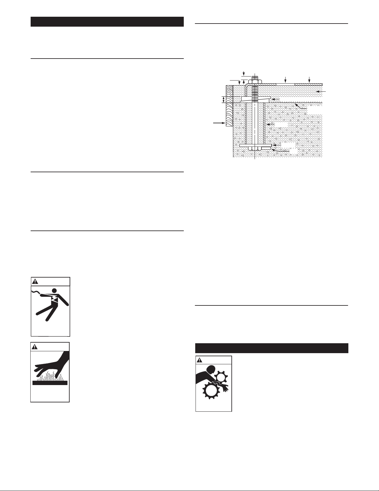
• A at substantial foundation surface MUST be provided to
avoid distortion and/or strain when tightening the foundation
bolts. A rubber mounting is acceptable to reduce noise or
excessive vibration.
• Tighten motor hold-down bolts BEFORE connecting piping
to pump.
Finished grouting
(1/4")
Grout hole Base
Leveling wedges or shims—left in place
Top of foundation—
clean and wet down
Sleeve
Washer
Lug
Figure 1
• It is recommended that the baseplate be grouted to a
foundation with solid footing. Refer to Figure 1.
• Place unit in position on wedges located at four points, two
below approximate center of driver and two below
approximate center of pump. Adjust wedges to level unit.
Level or plumb suction and discharge connections.
• Make sure bedplate is not distorted and nal coupling
alignment can be made within the limits of movement of
motor and by shimming, if necessary.
• Tighten foundation bolts nger tight and build dam around
foundation. Pour grout under bedplate making sure the areas
under the pump and motor feet are filled solid. Allow grout
to harden 48 hours before fully tightening foundation bolts.
• Tighten pump and motor hold-down bolts before aligning
shaft or connecting the piping to pump.
• Allow grout to harden for 48 hours before tightening 4
foundation bolts.
CLOSE-COUPLED UNITS
• Units must be installed horizontally.
• The motor feet MUST be bolted to a substantial surface that
is capable of complete and rigid support for the pump and
motor.
OPERATION AT OR NEAR
ZERO FLOW CAN CAUSE EXTREME HEAT, PERSONAL INJURY OR PROPERTY DAMAGE.
NOTICE: NO NOT RUN PUMP DRY OR SEAL
DAMAGE WILL RESULT.
• After stabilizing the system at normal operating conditions,
check the piping. If necessary, adjust the pipe supports.
• On frame-mounted units, coupling alignment may have
changed due to the temperature differential between pump
and motor. Recheck alignment following procedures and
hazard warnings in “COUPLING ALIGNMENT” section
of this manual.
4
Coupling Alignment
FAILURE TO DISCONNECT AND
LOCKOUT ELECTRICAL POWER
BEFORE ATTEMPTING ANY
MAINTENANCE CAN CAUSE
SEVERE PERSONAL INJURY.
Page 5
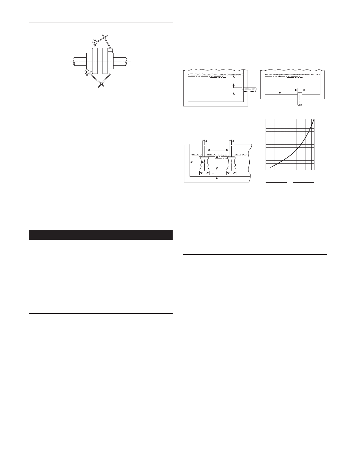
FRAME-MOUNTED UNITS ONLY
• Alignment MUST be checked prior to running. See Figure 2.
Parallel
• Use a foot valve or check valve ONLY if necessary for
priming or to hold prime during intermittent duty.
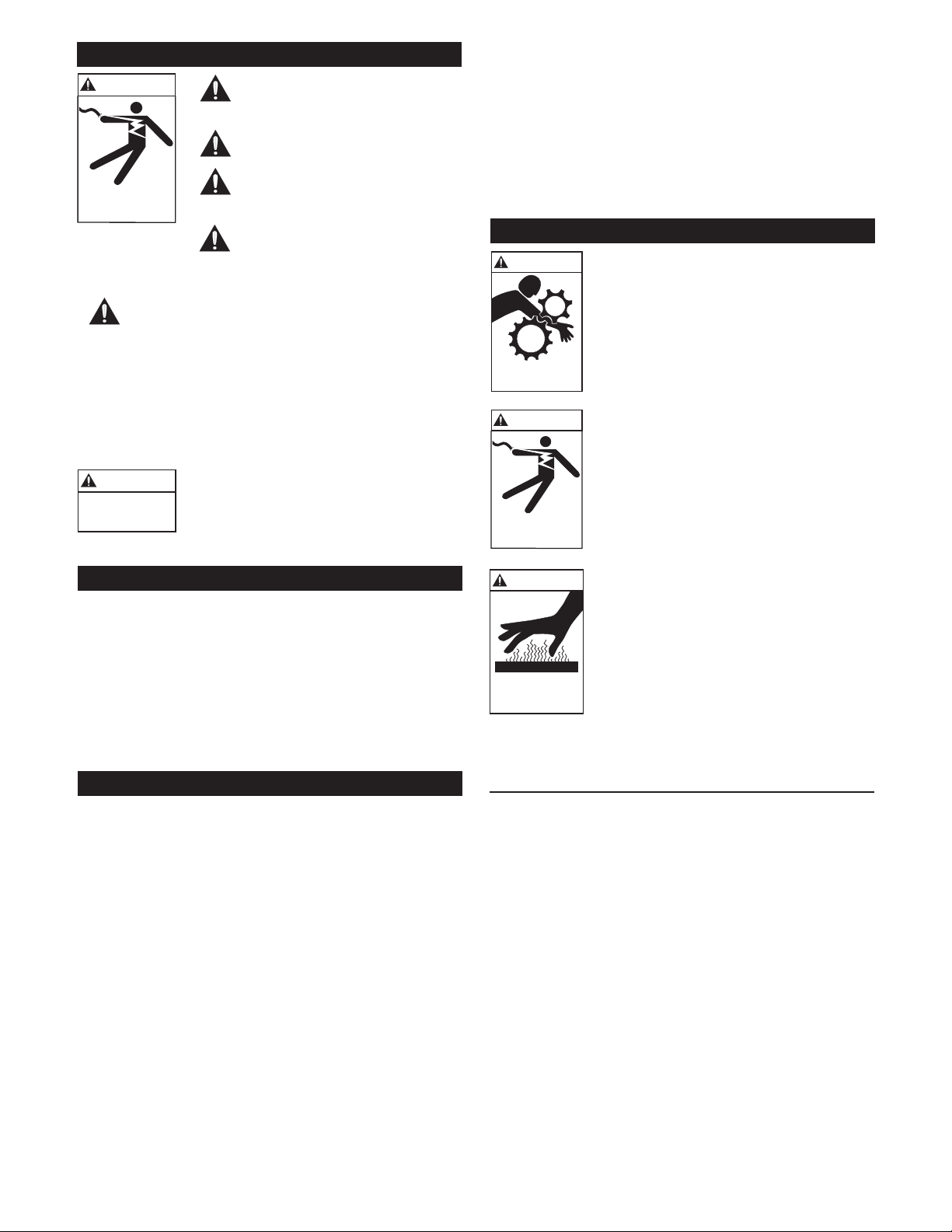
• The suction strainer or suction bell MUST be at least
3 times the suction pipe diameter area.
• Insure that the size and minimum submergence over suction inlet is sufficient to prevent air from entering pump
through a suction vortex. See Figures 3 through 6.
Angular
Figure 2
• Tighten all hold-down bolts before checking alignment.
• If realignment is necessary, always move the motor. Shim
as required.
• Parallel misalignment, shafts with axis parallel but not
concentric. Place dial indicator on one hub and rotate this
hub 360° while taking readings on the outside diameter of
the other hub. Parallel alignment is achieved when reading is
0.010" (0.254 mm) TIR, or less.
• Angular misalignment, shaft with axis concentric but not
parallel. Place dial indicator on one hub and rotate this hub
360° while taking readings on the face of the other hub.
Angular alignment is achieved when reading is 0.020"
(0.508 mm) TIR, or less.
• Final alignment is achieved when parallel and angular requirements are satisfied with motor hold-down bolts tight.
NOTICE: ALWAYS RECHECK BOTH ALIGNMENTS
AFTER MAKING ANY MECHANICAL
ADJUSTMENTS.
Piping
• Piping should be no smaller than pump’s discharge and
suction connections and kept as short as possible, avoiding
unnecessary fittings to minimize friction losses.
• All piping MUST be independently supported and MUST
NOT place any piping loads on the pump
NOTICE: DO NOT FORCE PIPING INTO PLACE
AT PUMP SUCTION AND DISCHARGE
CONNECTIONS.
• All pipe joints MUST be airtight.
PIPING – SUCTION
• For suction lifts over 10 ft. (3 m) and liquid temperatures
over 120° F (49° C), consult pump performance curve for
net positive suction head required (NPSHR).
• If a pipe size larger than pump suction is required, an eccentric pipe reducer, with the straight side up, MUST be
installed at the pump suction.
• If pump is installed below the liquid source, install a gate
valve in the suction for pump inspection and maintenance.
NOTICE: DO NOT USE THE GATE VALVE TO
THROTTLE PUMP. THIS MAY CAUSE LOSS
OF PRIME, EXCESSIVE TEMPERATURES
AND DAMAGE TO PUMP, VOIDING
WARRANTY.
• If the pump is installed above the liquid source, the following
MUST be provided:
• To avoid air pockets, no part of the piping should be above
the pump suction connection.
• Slope the piping upward from liquid source.
H min.
D
Figure 3 Figure 4
3.0D
min.
1.5D
min.
H min.
D min.
D D
2
H min.
H
16
15
14
13
12
11
10
9
8
7
6
5
4
3
2
H = Min. Submergence in feet
1
123456789101112 13141516
V = Velocity in feet per second
= GPM x 0.321
Area
GPM x 0.4085
D
V
2
D
Figure 5 Figure 6
PIPING – DISCHARGE
• Install a check valve suitable to handle the ow, liquids and
to prevent backflow. After the check valve, install an appropriately sized gate valve to be used to regulate the pump
capacity, pump inspection and for maintenance.
• When required, pipe increaser should be installed between
the check valve and the pump discharge.
AIR RELEASE LINE (4E & 6E)
It is essential to allow the air to escape from the discharge
line to atmosphere during the initial priming and re-priming
cycle. In systems with high discharge heads, it may be advisable
to install an air release line between the pump casing and
discharge check valve to aid their venting. The size of the
air release line is selected such that it does not significantly
affect the discharge capacity. You may install an air release line
through the filler plug hole if necessary. However, the preferred
location is in the discharge line – between the pump and the
discharge check valve – as close to the discharge check valve
as possible. We recommend the following line sizes for the
following pumps:
4" pump – ¾" line
6" pump – 1" line
NOTES:
1. This line size may be increased or decreased depending on
application.
2. Direct the air release line back into the sump (not into
the pump suction line). Leave the end of the line open to
atmosphere. Do not submerge into the liquid being
pumped.
3. The air release line may clog, particularly if a shut-off
valve is installed in the line and is closed during operation.
If this condition occurs, either use a larger line or leave the
shut-off valve open during pumping operation. To aid in
maintaining air release lines, fit them with crosses
instead of elbows.
5
Page 6
Hazardous machinery
can cause personal
injury or death.
WARNING
WARNING
Hazardous voltage
can shock, burn or
cause death.
WARNING
Hazardous voltage
can shock, burn or
cause death.
WARNING
Hazardous
voltage
Wiring and Grounding
Extreme heat can
cause personal injury
or property damage.
WARNING
Install, ground and wire according
to local and National Electrical Code
Requirements.
Install an all leg electrical power
disconnect switch near the pump.
Disconnect and lockout electrical
power before installing or servicing
the pump.
Electrical supply MUST match
pump’s nameplate specications. Incorrect voltage can cause fire, damage
motor and void the warranty.
Motors without built-in protection MUST be provided
with contactors and thermal overloads for single phase
motors, or starters with heaters for three phase motors.
See motor nameplate.
• Use only copper wire to motor and ground. The ground wire
MUST be at least as large as the wire to the motor. Wires
should be color coded for ease of maintenance.
• Follow motor manufacturer’s wiring diagram on the motor
nameplate or terminal cover carefully.
FAILURE TO PERMANENTLY
GROUND THE PUMP, MOTOR AND
CONTROLS BEFORE CONNECTING
TO ELECTRICAL POWER CAN CAUSE
SHOCK, BURNS OR DEATH.
NOTE: Tightening the jack-screws will increase the front
clearance and tightening the capscrews will decrease the
front clearance.
Tighten one set of screws and loosen the other to go in
the direction required. Tighten locknut (111).
NOTE: Maximum allowable bearing carrier (110) pull
back movement is 1⁄8", (i.e. from the condition when
impeller is “just” touching the diffuser you can push back
the bearing carrier assembly by 1⁄8".
Operation
DO NOT OPERATE FRAME MOUNTED
OR SAE UNITS WITHOUT SAFETY
GUARDS IN PLACE OR SEVERE
PERSONAL INJURY MAY RESULT.
SPLASHING OR IMMERSING OPEN
DRIP PROOF MOTORS IN FLUID
CAN CAUSE FIRE, SHOCK, BURNS OR
DEATH.
NOTICE: INCORRECT ROTATION MAY CAUSE
DAMAGE TO THE PUMP AND VOIDS
THE WARRANTY.
• Correct rotation is right-hand, CLOCKWISE when viewed
• To reverse three phase motor rotation, interchange any two
(Applicable for models with open impellers)
The impeller running clearance, the distance between the
impeller vanes and diffuser is adjusted at the factory prior
to shipment to .020"-.030". To adjust this clearance in the
field, shut down the pump, disconnect power supply to
the pump and use the following instructions.
1. Unscrew three jack-screws (112), jam-nuts (111) and
bearing carrier capscrews (45).
2. Adjust the jack-screws and capscrews until the
impeller just touches the diffuser (46) (slight rub).
Tighten the jam nuts.
3. Measure the gap between bearing housing surface
(coupling END) and bearing carrier flange.
4. Adjust jack-screws, jam-nuts and capscrews to
pull out the rotating assembly, until the gap between
bearing housing surface and bearing carrier flange
measures .020"-.030" more than previously
measured gap.
Rotation
from the motor end. For frame mounted units, switch power
on and off quickly to observe rotation. On close coupled
units, remove motor end plug or cover to observe rotation.
power supply leads.
Impeller Running Clearance (6E1 Only)
OPERATION AT OR NEAR ZERO
FLOW CAN CAUSE EXTREME HEAT,
PERSONAL INJURY OR PROPERTY
DAMAGE.
NOTICE: NO NOT RUN PUMP DRY OR SEAL
DAMAGE WILL RESULT.
STARTING
Follow the motor manufacturer’s instructions carefully.
Before starting fill the pump casing with liquid through
the priming plug provided. Your pump has been designed
to prime itself in a few minutes. High suction lifts require
additional time and reduce the performance of the pump.
Should you have difficulty, refer to the “Troubleshooting
Guide” table.
Goulds Water Technology self-priming pumps prime
and reprime themselves providing the casing is filled
with liquid. Should you lose this liquid from the casing
accidentally or by draining purposely, it will be necessary
to refill it with liquid before starting.
2P through 4P – Check grease in the bearing housing
cavity. Units are shipped with grease but should be
checked before starting. (Refer to Lubrication section for
more details.)
4E and 6E – Units are shipped without oil in the bearing
housing cavity. Fill this cavity with the proper amount
and proper grade of oil. (Refer to Lubrication section for
more details.)
6
Page 7
Check drive coupling alignment. (Refer to Coupling
Alignment section for instructions.)
Check motor wiring.
WARNING
1. All electrical work must be done
by a licensed electrician.
2. Before working on pump and/or
motor be certain the electrical power
is off at the main junction box.
Hazardous voltage
can shock, burn or
cause death.
3. Disconnect the fuse or circuit breaker
and have the main switch tagged
“DO NOT ENERGIZE THIS
SWITCH, PERSONNEL WORKING
ON EQUIPMENT.”
4. Some motors are equipped with built-in thermal
overloads to shut off the motors in the event the
temperature becomes excessive (as a result of
mechanical or electrical problems, such as low
voltage, poor ventilation, overloaded lines, etc.).
These motors will restart automatically as the motor
cools down. For safety sake, DO NOT work on any
motor without shutting off the electricity.
5. Never operate an electric motor driven pump
without properly grounding the motor frame. Serious
injury or death by electrocution could result.
6. Drain pump casing completely before taking pump
apart. It is advisable to flush the inside of the casing
with water before taking pump apart.
WARNING
7. Never start pump before putting
back all necessary guards such as
coupling guard.
Hazardous Machinery
• After stabilizing the system at normal operating conditions,
check the piping. If necessary, adjust the pipe supports.
• On frame-mounted units, coupling alignment may have
changed due to the temperature differential between pump
and motor. Recheck alignment following procedures and
hazard warnings in “COUPLING ALIGNMENT” section of
this manual.
SEASONAL SERVICE
• To REMOVE pump from service, remove drain plug and
drain all unprotected piping.
• To RETURN pump to service, replace drain plug using
Teflon™ tape or equivalent on male threads.
• Reconnect suction line if removed, examine union and repair
if necessary.
• Refer to OPERATION section of manual.
Disassembly
• Follow ALL warnings and instructions in the “MAINTE-
NANCE” section of this manual.
• Close-coupled units: Remove motor hold-down bolts.
• Frame-mounted units: Remove coupling guard, spacer, cou-
pling and frame hold-down bolts.
LIQUID END
1. Remove casing bolts (47).
2. Remove back pull-out assembly from casing (1).
Discard gasket (8).
3. Remove diffuser and o-ring.
NOTICE: DO NOT INSERT SCREWDRIVER BETWEEN
IMPELLER VANES TO PREVENT ROTATION.
4. On close-coupled units, remove motor end plug or cover
to expose screwdriver slot or flats on end of motor shaft.
5. While restraining shaft with an appropriate tool (close coupled units) or with a strap wrench (frame-mounted
units) remove impeller bolt/nut (4). Impeller bolt/nut may
need to be heated with torch to remove. Discard.
NOTICE: EXERCISE CAUTION WHEN HANDLING
HOT IMPELLER BOLT/NUT.
6. Remove impeller washer (5).
7. Insert two pry bars, 180° apart, between impeller and
seal housing (10). CAREFULLY pry off impeller.
8. Remove impeller key (37).
9. Remove seal housing bolts (33) and seal housing (10)
pulling with it the mechanical seal assembly. Discard seal
assembly.
10. Inspect shaft sleeve (24). If badly scored, remove by
heating with torch. Discard.
11. Push out the mechanical seal stationary seat from the
seal housing. Discard.
NOTE: Check impeller and diffuser for any broken vanes or
wear. Replace it if necessary. Also check diffuser o-ring (7).
Replace if damaged.
DISASSEMBLY OF BEARING FRAME (P-SERIES)
1. Remove deflector (63) from shaft.
2. Remove bearing cover (80).
3. Remove shaft assembly from frame.
4. Remove lip seals (69, 81) from bearing frame (70) and
bearing cover (80) if worn. Discard.
5. Remove retaining ring (71).
6. Use bearing puller or arbor press to remove ball
bearings (74, 78).
DISASSEMBLY OF BEARING FRAME (4E AND 6E)
1. Drain bearing housing oil cavity by removing drain plug
(28) for oil lubrication bearing housing.
2. Remove capscrews (33) to disassemble bearing housing
(31) from bracket (67).
NOTE: Check gasket (8) if worn, replace it.
3. Remove the shaft assembly with bearings and bearing
carrier (110) out of the bearing housing (31).
4. Check both lip seals (42), replace if necessary.
5. Remove the snap ring (108) from the shaft (38).
6. Check the bearings. If they feel rough when turning by
hand, replace the bearings.
Reassembly
• All parts should be cleaned before assembly.
NOTICE: O-RING SHOULD BE REPLACED AFTER ANY
DISASSEMBLY OF UNIT.
7
Page 8
Hazardous fluids can
cause personal injury
or property damage.
WARNING
WARNING
Hazardous voltage
can shock, burn or
cause death.
Hazardous pressure can
cause personal injury,
property damage or death.
CAUTION
BEARING FRAME
1. Replace lip seals if removed.
2. Replace ball bearings if loose, rough or noisy when rotated.
3. Check shaft (38) for runout. Maximum permissible is
0.002" (0.05 mm) TIR.
4. Refer to the “MAINTENANCE” section of this manual
for bearing frame lubricating instructions.
5. Refer to the “MAINTENANCE” section of this manual
for bearing replacement of the E-Series bearing frame.
LIQUID END
1. Inspect shaft removing any debris or burrs.
2. Treat shaft with LOCQUIC® Primer “T”, or equivalent,
following manufacturer’s instructions carefully.
3. When replacing shaft sleeve, spray new shaft sleeve’s bore
with LOCQUIC® Primer “T”, or equivalent. Let parts dry
and then apply LOCTITE® #271 on the same surfaces.
Slide new sleeve, I.D. chamfer end first, over shaft with a
twisting motion, wipe off excess. Let cure according to
instructions.
NOTICE: MECHANICAL SEAL MUST BE REPLACED
WHENEVER SEAL HAS BEEN REMOVED.
FOLLOW SEAL MANUFACTURER’S
INSTRUCTIONS CAREFULLY. FOR PACKED
BOX PUMPS SEE “PACKED BOX
INSTRUCTIONS”.
4. The stationary seal seat may be dipped in water to ease
installation. Place stationary seal seat squarely into seal
housing bore. Cover the polished face of the seat with
a thin piece of cardboard or paper towel. Press seat firmly
into bore using a round piece of plastic or wood that
disperses the force over the entire seal face. NOTE: If
mechanical seal is supplied with a spring retainer, remove
and discard the retainer.
5. Place adapter, concave face pointing up, over motor/frame
shaft and lower it onto the mounting face.
6. Install seal housing on adapter. Exercise care in that the
motor shaft does not dislodge or damage seal seat.
7. Fully and squarely install the rotary assembly of seal
against the stationary seat.
NOTICE: REPLACE IMPELLER BOLT/NUT AND
WASHER WHENEVER IMPELLER IS REMOVED.
8. Install impeller key in shaft keyway. Mount impeller on
shaft and push until it bottoms. Hold in place.
9. Install new impeller washer.
Reverse disassembly procedure to reassemble the pump.
NOTE: Make sure all gaskets, o-ring, rubber check valve and
seal assembly are in good condition before reassembly.
HYDROTEST
NOTE: If hydrostatic test is required in the field, it must
be performed with check valve removed or with partially
open check valve.
The hydrotest pressure is generally 1½ times the working
pressure.
To set up the pump for hydrostatic test follow these
instructions:
Before hydrotesting the pump all air must be removed
from the suction priming chamber. This is done by:
(a) Removing ¼" pipe plug from top of the suction
inlet (50).
(b) Install a ¼" pet cock valve (not supplied by Goulds
Water Technology) in place of pipe plug.
(c) With pet cock open fill casing (1) with fluid being
pumped through filler plug (129) provided on top of
casing. Do not close pet cock until all air is out of
casing (as shown by a solid stream of liquid coming
out of pet cock).
(d) Close pet cock, reinstall filler plug. Unit is now ready
for hydrotest.
Maintenance
FAILURE TO DISCONNECT AND
LOCKOUT ELECTRICAL POWER
BEFORE ATTEMPTING ANY
MAINTENANCE CAN CAUSE SHOCK,
BURNS OR DEATH.
FAILURE TO RELIEVE SYSTEM
PRESSURE AND DRAIN SYSTEM
BEFORE ATTEMPTING ANY
MAINTENANCE CAN CAUSE
PROPERTY DAMAGE, PERSONAL
INJURY OR DEATH.
IF PIPING HAZARDOUS OR TOXIC
FLUIDS, SYSTEM MUST BE FLUSHED
PRIOR TO PERFORMING SERVICE.
CLOSE-COUPLED UNITS
• Bearings are located in and are part of the motor. For lubrication information, refer to motor manufacturer’s instructions.
FRAME-MOUNTED UNITS
P-Series
• S Frame has greased for life bearings. No regreasing is
possible or necessary.
• ML frame should be regreased every 2,000 hours or at a
three month interval, whichever occurs first. Use a #2
sodium or lithium based grease. Fill until grease comes
out of relief fittings, or lip seals, then wipe off excess.
E-Series
• Set and maintain oil level as shown below.
1
/4"
MAX.
MIN.
SIGHT WINDOW
• Follow motor and coupling manufacturer’s lubrication
instructions.
• Recheck coupling alignment.
Approximately
52 fluids ounces.
8
Page 9

SHAFT AND BEARING REPLACEMENT (E-Series)
If shaft or bearing replacement is necessary, follow these
instructions. (Shut down the pump and disconnect power
supply to the pump before working on pump.)
1. Install the front (impeller end) bearing (36) on
the shaft (38).
2. Slide the carrier retaining ring (106) onto the
shaft (38) over the coupling end.
3. Install the rear (coupling end) bearing (117) on
the shaft (38).
4. Install the retaining ring (108) onto the shaft (38).
Add shims (107) between the retaining ring (108)
and the rear bearing (117) if required to lock the
rear bearing (117) on to the shaft axially.
5. Install O-ring (109) into the O.D. groove of the
bearing carrier (110).
6. Slide the bearing carrier (110) with o-ring over the
rear bearing such the rear bearing slides into the
bearing carrier (110). Install the retaining ring (106)
in place inside bearing carrier.
7. Insert shaft assembly with bearings and carrier into
the housing (31).
SEAL INSTALLATION INSTRUCTION
Seal is precision made. Handle carefully. Do not scratch
seal face.
1. Remove old seal. Clean shaft and all seal cavity
surfaces thoroughly.
2. Coat carbon washer, inside surface of rubber boot,
and rubber o-ring with a clean oil film.
3. Push stationary assembly into cavity, seating it
firmly and squarely with finger pressure only. DO
NOT use screwdriver or any tool which might
damage the stationary assembly.
4. Slide bellows assembly on shaft as far as possible,
pushing against rubber tail section only. Ease
bellows assembly into place. DO NOT DRIVE
WITH A HAMMER.
5. Install bellows spring with one end on flange of metal
seal flange. Some seal assemblies use a tapered spring.
On these, the smaller diameter fits on metal seal
flange.
6. Complete assembly of other pump parts.
A short “run-in” period may be necessary to provide a
tight seal joint.
CAUTION: Never run a seal dry for any length of time.
NOTE: Please make note that all “P” Series pumps are
equipped with shaft sleeve.
SHAFT SLEEVE INSTALLATION (2P, 3P, 4P ONLY)
Follow these instructions when applying loctite between
the shaft sleeve and shaft surface.
(a) Surface to be coated with loctite must be free of dirt
and grease. Wash with degreasing solvent if necessary.
(b) Spray these surfaces with loctite primer type “T”.
DO NOT OVERSPRAY. The thinnest film of primer
is best. Avoid skin contact or repeated breathing of
primer vapor. Allow three to four minutes for primer
to dry.
(c) Apply a coat (.005" or less thick) of loctite 271 (red)
to both shaft and inside of shaft sleeve.
(d) Slide shaft sleeve over the shaft all the way against
shaft shoulder. Make sure the chamfer on the I.D.
of the shaft sleeve is towards the shaft shoulder not
towards the impeller. Allow 5-10 minutes to cure if
primer type “T” is used, or 10-15 minutes if primer is
not used to attain full strength of loctite.
NOTE:
1. An evenly applied coat of loctite on both surfaces
will prevent leakage under shaft sleeve.
2. To remove shaft sleeve heat sleeve surface to
300º-350ºF with heat gun and tap gently on sleeve
to remove.
CHECK VALVE REPLACEMENT
To remove suction check valve follow these steps:
(a) Disconnect suction piping from suction inlet (50).
(b) Remove complete assembly, which includes suction
inlet (50) and check valve assembly.
(c) Remove shoulder bolts (54) to remove check valve
keeper plate (53) and rubber check valve (51).
If any of the parts of the check valve assembly are
damaged i.e. suction inlet (50), check valve (51), shoulder
bolt (54) and keeper plate (53), replace. Make sure the
sealing surface on suction inlet (angled surface) is not
damaged.
NOTE: Latest design check valve uses shoulder bolt (54)
instead of stud, space tube, locking nut, and washer.
Follow above procedure in reverse to reassemble the
pump.
NOTE: Make sure all gaskets, o-ring, rubber check
valve and seal assembly are in good condition before
reassemby. Replace as is necessary.
WINTER STORAGE
1. Wash off exterior of pump.
2. Flush suction line, discharge line, pump casing,
impeller and diffuser of all solids by pumping clear
liquid for a short time.
3. Drain pump casing, suction line and discharge line.
4. If complete draining is impossible add small amount
of anti-freeze into the pump casing. Rotate shaft for
mixing.
5. If the bearings are oil lubricated drain the old oil
from bearing housing and refill housing cavity with
proper grade of oil. (Refer to Maintenance section).
6. Seal off suction and discharge ports of pump casing.
7. Store the units in dry clean area if possible.
8. Motor windings should be protected from excessive
moisture. Follow motor manufacturer’s instructions.
9. Spray interior of pump casing with commercially
available anti-rust and anti-corrosion petroleum
aerosol.
10. Once a month rotate the pump shaft during storage
if possible.
9
Page 10

WARNING
Hazardous voltage
can shock, burn or
cause death.
Troubleshooting
DISCONNECT AND LOCKOUT
ELECTRICAL POWER BEFORE
ATTEMPTING ANY MAINTENANCE.
FAILURE TO DO SO CAN CAUSE A
SHOCK, BURN OR DEATH.
NOTE: Before implementing any remedial action recommended in the following Troubleshooting guide, refer to
“Recommended Precautions” and “Warning” sections of this manual. The following are some common causes of
problems that may arise.
Symptoms Probable Cause Recommended Action
Will not prime No liquid in pump casing (1). Fill pump casing with liquid being
pumped.
Loose suction inlet (50). Tighten bolts.
Worn suction inlet gasket (49). Replace with new gaskets.
Loose drain plug (2). Tighten plug, use pipe dope or
Teflon tape.
Worn pump shaft seal assembly (17). Install new seal.
Leaky suction line. Fix leaky suction. Check all
gasketed surface.
Worn diffuser gasket (7). Replace diffuser gasket.
Suddenly stops pumping. Clogged suction line or suction Clean suction line and strainer
strainer (if used).
Stops pumping until motor is Collapsing suction hose lining. Replace suction line and strainer.
stopped and restarted.
Slowly stops pumping. Clogged impeller (6) or (91), Clean out debris from impeller eye
diffuser (46), check valve (51) or area, suction check valve, or from
suction line. diffuser vanes.
Excessive leakage around shaft. Work pump shaft seal (17). Replace seal assembly.
Will not hold prime. Dislodged or worn check valve (51). Clean or replace check valve. Clean
sealing surface.
Small leak in suction line. Check suction hose or piping for
leak.
Worn seal or packing. Replace seal or packing.
Poor performance Impeller (6) or (91), seal Install new impeller, seal or diffuser.
assembly (17) or diffuser (46).
Motor not up to speed: (a) larger lead wires required
(a) low voltage (b) worn bearings (b) replace bearings.
Noisy operation Worn motor bearings. Replace.
Low discharge head. Throttle discharge.
Impeller clogged. Remove and clean impeller.
Worn coupling or misalignment. Replace or realign coupling.
Units operating at extreme left or Adjust for best performance point
right end of performance curve of operation.
(capacity too high or too low).
Bearings running dry. Check oil level or grease –
add if required.
10
Page 11
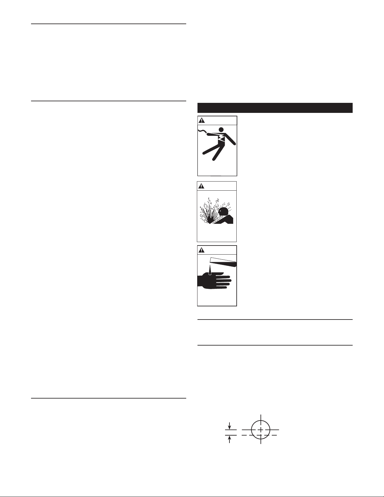
Repair Parts
PRIME LINE FRAME MOUNT REPAIR PARTS – 2P, 3P, 4P
49
27
27
129
54
53
51
27
50
2
2
58
57
37
17
8
48
10
7
47
32
33
46
24
67
66
65
64
71 72
69
70
6
5
4
63 74 75 77 78 79 8076 81
Key Description Key Description Key Description Key Description
1 Casing 32 Lockwasher 57 Capscrew 129 Bushing
2 Pipe Plug 33 Capscrew 58 Lockwasher 74 Ball Bearing
4 Bolt, Impeller *37 Key, Impeller 64 Hexnut 75 Grease Fitting (ML)
5 Washer, Impeller 46 Diffuser 65 Capscrew 76 Shaft
•6 Impeller 47 Capscrew 66 Lockwasher 77 Foot
*7 O-Ring 48 Lockwasher 67 Adapter, Motor 78 Ball Bearing
*8 Gasket, Diecut *49 Gasket, Diecut 68 Stud 79 Grease Fitting (ML)
10 Seal Housing 50 Inlet, Suction 69 Lip Seal 80 Bearing Cover
•17 Seal,SingleMech •51 Valve,Check 70 BearingFrame 81 LipSeal
*24 Sleeve, Shaft 53 Keeper 71 Retaining Ring 82 Key
27 Pipe Plug 54 Shoulder Bolt 72 Hex Head Cap Screw
* Recommended Spare parts
• RecommendedDistributorStock,ExportSparesandCriticalService.
82
11
Page 12
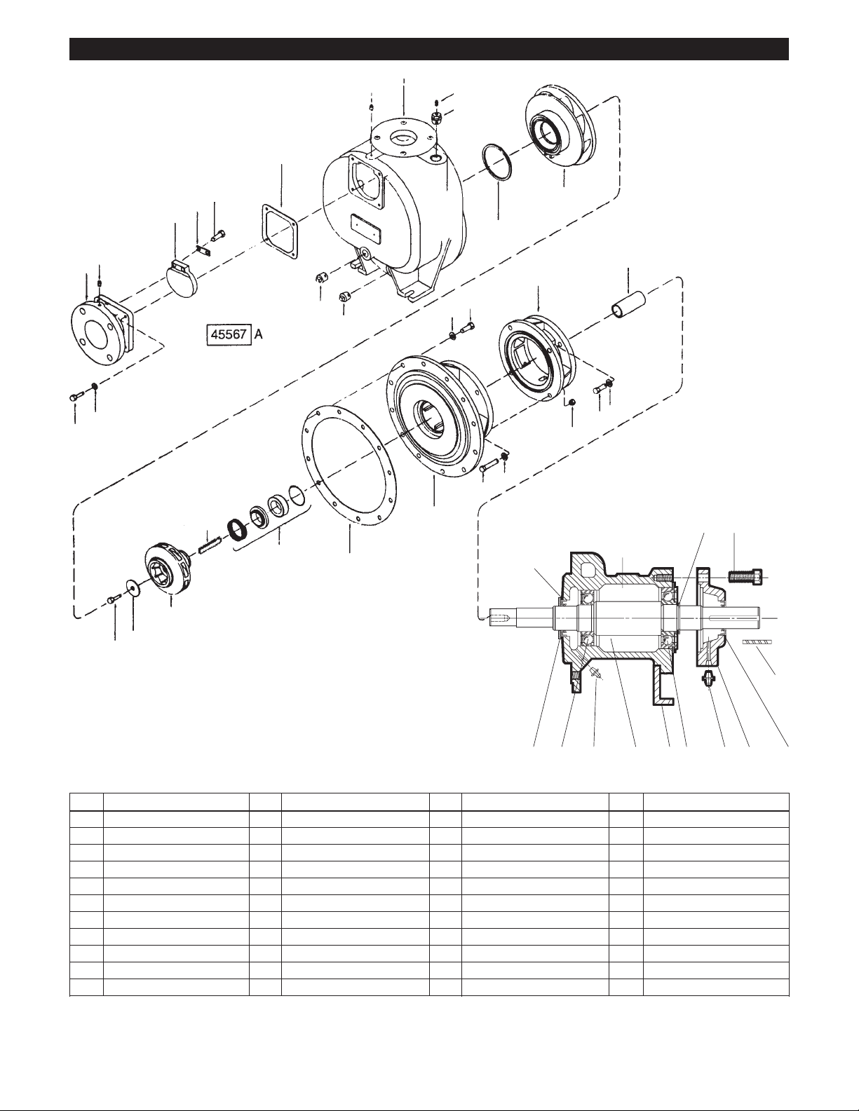
Repair Parts (Continued)
PRIME LINE CLOSE-COUPLED CROSS SECTION – 2P, 3P, 4P
50 49 27 54 1 8 10
27
6
4
5
37
53
51
2
7
46
17
67
24
63 69
72
68
2
Key Description Key Description Key Description
1 Casing •17 Seal,SingleMech 53 Keeper
2 Pipe Plug *24 Sleeve, Shaft 54 Shoulder Bolt
4 Bolt, Impeller 27 Pipe Plug 63 Slinger
5 Washer, Impeller *37 Key, Impeller 67 Adapter, Motor
•6 Impeller,Closed 46 Diffuser 68 Stud
*7 O-Ring *49 Gasket, Diecut 69 Motor (Specify)
*8 Gasket, Diecut 50 Inlet, Suction 72 Riser
10 SealHousing •51 Valve,Check 73 Base,Motor
* Recommended Spare parts
• RecommendedDistributorStock,ExportSparesandCriticalService.
73
12
Page 13
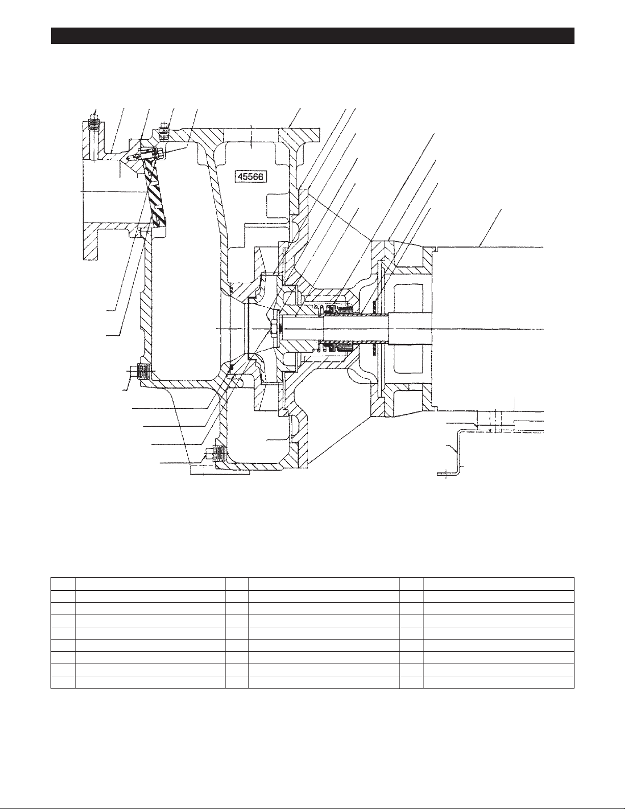
Repair Parts (Continued)
PRIME LINE CLOSE COUPLED REPAIR PARTS – 2P, 3P, 4P
49
1
27
27
129
54
53
51
27
50
2
2
58
57
17
8
7
47
48
10
46
63
67
32
33
37
66
24
66
65
64
69
70
71
6
5
4
Key Description Key Description Key Description
1 Casing *37 Key, Impeller 58 Lockwasher
2 Pipe Plug 46 Diffuser 63 Slinger
4 Bolt, Impeller 47 Capscrew 64 Hexnut
5 Washer, Impeller 48 Lockwasher 65 Capscrew
•6 Impeller *49 Gasket,Diecut 66 Lockwasher
*7 O-Ring 50 Inlet, Suction 67 Adapter, Motor
*8 Gasket,Diecut •51 Valve,Check 68 Stud
10 Seal Housing 52 Spacer 69 Motor (Specify)
•17 Seal,SingleMech 53 Keeper 70 Capscrew
*24 Sleeve, Shaft 54 Stud 71 Lockwasher
27 Pipe Plug 55 Flatwasher 72 Riser
32 Lockwasher 56 Locknut 73 Base, Motor
33 Capscrew 57 Capscrew 129 Bushing
* Recommended Spare parts
• RecommendedDistributorStock,ExportSparesandCriticalService.
73
72
13
Page 14
Repair Parts (Continued)
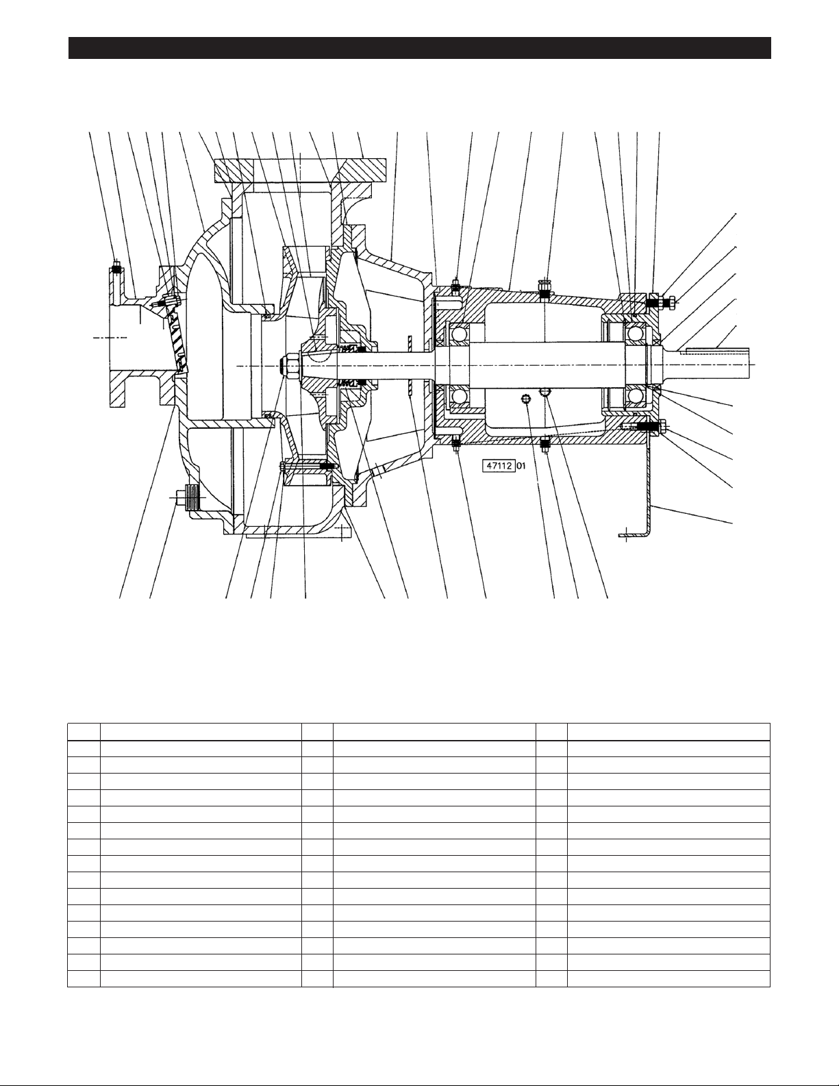
PRIME LINE CROSS SECTION – 4E, 6E
50 51 53 118 93132
27
7 46 37 91 10196 67 42 27 36 3031130 117 109 110106
111
112
42
38
39
108
107
2 4 133 134 8549 63 27 29, 27 28 2817
Key Description Key Description Key Description
1 Casing 37 Key, Impeller 96 Gasket, Diecut
2 Pipe Plug 38 Shaft 106 Ring, Retaining
4 Locknut, Impeller 39 Key, Coupling 107 Shim, Bearing
5 Washer, Curved, Impeller 42 Lip Seal 108 Ring, Retaining
7 O-Ring 44 Lockwasher 109 O-Ring, Molded
8 Gasket, Diecut 45 Capscrew 110 Carrier, Bearing
10 Seal Housing 46 Diffuser 111 Hexnut, Jam
17 Seal, Single Mechanical 49 Gasket, Diecut 112 Jackscrew
27 Pipe Plug 50 Inlet, Suction 117 Bearing, Rear
28 PipePlug 51 Valve,Check 118 Screw,Shouldered
29 Oiler, Optional 53 Keeper 130 Adaptor, Plate
30 Vent,Filter 63 Slinger 132 Cover,Casing
31 Housing, Bearing 67 Bracket 133 Capscrew
35 Foot, Mounting 92 Impeller, Open 134 Lockwasher
36 Bearing, Front 93 Gasket, Diecut
* Recommended Spare parts
• RecommendedDistributorStock,ExportSparesandCriticalService.
45
44
35
14
Page 15
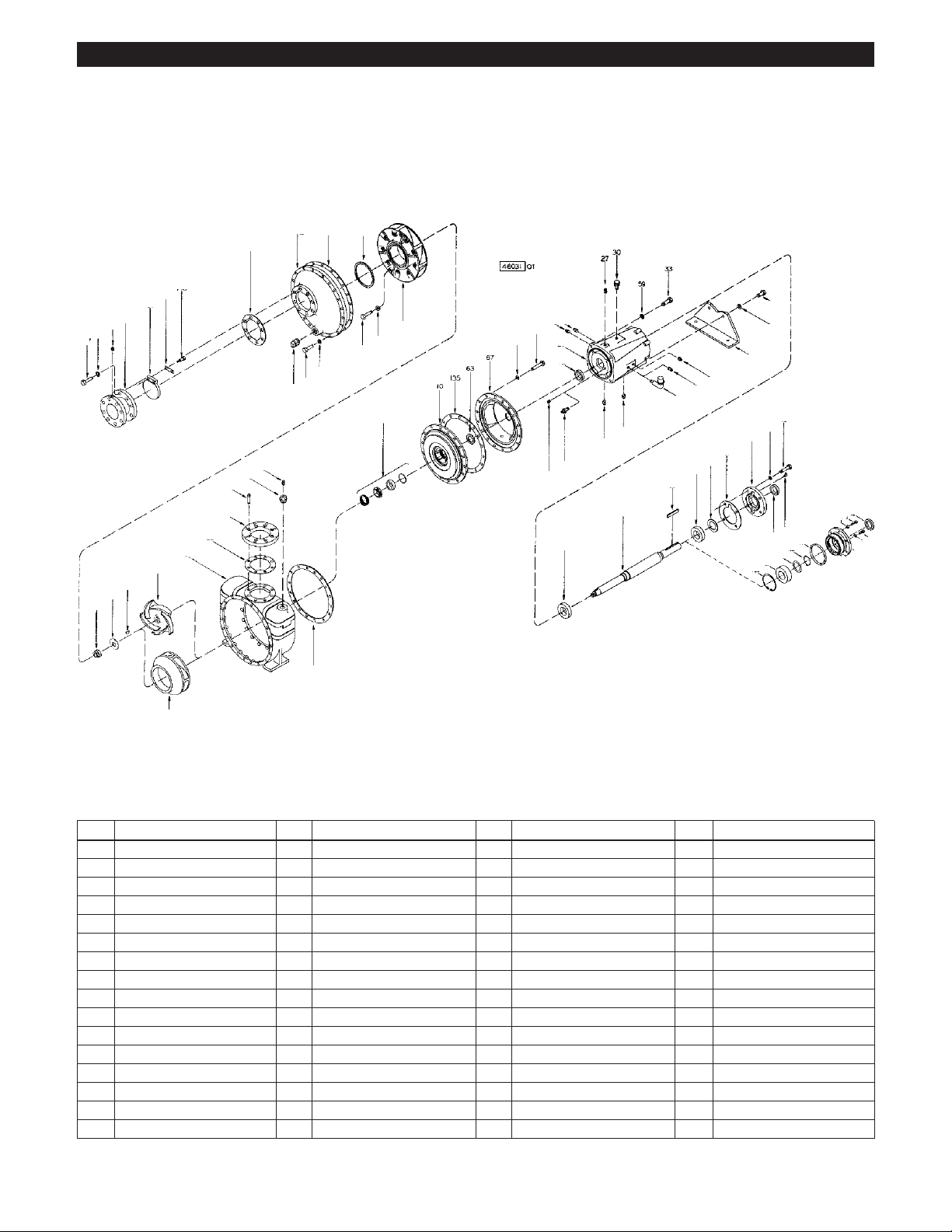
Repair Parts (Continued)
PRIME LINE REPAIR PARTS – 4E, 6E
132
7
93
49
118
53
51
50
27
58
57
59
92
2
133
46
134
27 28
47
44
31
42
28
27
29
17
28
27
27
129
131
130
96
1
61
26
39
38
36
41
40
36
91
37
5
4
34
59
35
45
44
43
112
42
111
106
117
62
109
42
108
107
44
110
45
8
6
Key Description Key Description Key Description Key Description
1 Casing 34 Capscrew 51 Valve,Check 109 O-Ring
2 Pipe Plug 35 Foot, Mounting 53 Keeper 110 Carrier, Bearing
4 Locknut, Impeller 36 Bearing, Front 57 Capscrew 111 Hex Nut, Jam
5 Washer, Curved, Impeller 37 Key Impeller 58 Lockwasher 112 Capscrew
6 Impeller, Closed 38 Shaft 59 Lockwasher 117 Bearing, Rear
7 O-Ring 39 Key, Coupling 61 Fitting, Hydraulic 118 Screw, Shoulder
8 Gasket, Diecut 40 Shim, Bearing 62 Fitting, Hydraulic 129 Bushing
10 Seal Housing 41 Gasket, Diecut 63 Slinger 130 Adapter, Plate
17 Seal, Single Mech. 42 Lip Seal 67 Bracket 131 Capscrew, Socket
26 Pipe Plug 43 Cap, Bearing 91 Impeller, Open 132 Cover, Casing
27 Pipe Plug 44 Lockwasher 92 Capscrew 133 Capscrew
28 Pipe Plug 45 Capscrew 93 Gasket, Diecut 134 Lockwasher
29 Oiler (Optional) 46 Diffuser 96 Gasket, Diecut 135 Shim, Lantern
30 Vent,Filter 47 Capscrew 106 Ring,Retaining
31 Housing, Bearing 49 Gasket, Diecut 107 Shim, Bearing
33 Capscrew 50 Inlet, Suction 108 Ring, Retaining
15
Page 16

GOULDS WATER TECHNOLOGY LIMITED WARRANTY
This warranty applies to all water systems pumps manufactured by Goulds Water Technology.
Any part or parts found to be defective within the warranty period shall be replaced at no charge to the dealer during the warranty period. The warranty period shall exist for a
period of twelve (12) months from date of installation or eighteen (18) months from date of manufacture, whichever period is shorter.
A dealer who believes that a warranty claim exists must contact the authorized Goulds Water Technology distributor from whom the pump was purchased and furnish complete
details regarding the claim. The distributor is authorized to adjust any warranty claims utilizing the Goulds Water Technology Customer Service Department.
The warranty excludes:
(a) Labor, transportation and related costs incurred by the dealer;
(b) Reinstallation costs of repaired equipment;
(c) Reinstallation costs of replacement equipment;
(d) Consequential damages of any kind; and,
(e) Reimbursement for loss caused by interruption of service.
For purposes of this warranty, the following terms have these definitions:
(1) “Distributor” means any individual, partnership, corporation, association, or other legal relationship that stands between Goulds Water Technology and the dealer in
purchases, consignments or contracts for sale of the subject pumps.
(2) “Dealer” means any individual, partnership, corporation, association, or other legal relationship which engages in the business of selling or leasing pumps to customers.
(3) “Customer” means any entity who buys or leases the subject pumps from a dealer. The “customer” may mean an individual, partnership, corporation, limited liability
company, association or other legal entity which may engage in any type of business.
THIS WARRANTY EXTENDS TO THE DEALER ONLY.
Xylem, Inc.
2881 East Bayard Street Ext., Suite A
Seneca Falls, NY 13148
Phone: (800) 453-6777
Fax: (888) 322-5877
www.xyleminc.com/brands/gouldswatertechnology
Goulds is a registered trademark of Goulds Pumps, Inc. and is used under license.
© 2012 Xylem Inc. IM191 Revision Number 3 July 2012
Page 17

MANUAL DE INSTRUCCIÓN
IM191
Motorizadas: Modelos 4E y 6E de acoplamiento largo
Modelos 2P, 3P, 4P de acoplamiento largo y acoplamiento próximo
®
Serie Marlow Prime Line
Bombas centrífugas de autocebadura
INSTRUCCIONES DE INSTALACIÓN, FUNCIONAMIENTO Y MANTENIMIENTO
Page 18

Índice
Sección Página
Precauciones recomendadas ................................................................................................................................................19
Instrucciones de operación ...................................................................................................................................................20
Alineación de acoplamiento ................................................................................................................................................. 20
Tuberías ................................................................................................................................................................................21
Cableado y conexión a tierra ................................................................................................................................................22
Rotación ................................................................................................................................................................................22
Huelgo de funcionamiento del impulsor ............................................................................................................................. 22
Funcionamiento ...................................................................................................................................................................22
Desensamble ........................................................................................................................................................................23
Reensamble .........................................................................................................................................................................24
Mantenimiento ....................................................................................................................................................................25
Investigación y solución de fallas ......................................................................................................................................... 27
Refacciones ........................................................................................................................................................................... 28
Garantía limitada .................................................................................................................................................................. 34
Información del propietario
Modelo de bomba
Número de serie
Distribuidor
Teléfono del dist.
Fecha de compra
Fecha de instalación
18
Page 19

DANGER
WARNING
CAUTION
Felicidades
Usted es ahora propietario de una bomba Goulds Water Technology. Esta bomba se inspeccionó y se sometió cuidadosamente
a pruebas finales antes de autorizar su traslado. Para obtener su
máximo desempeño, por favor siga las sencillas instrucciones de
este manual.
Precauciones recomendadas
1. Si existe la posibilidad de que haya aire atrapado en
la caja de la bomba, instale un dispositivo de
ventilación automático para purgar el aire.
2. Todos los motores eléctricos requieren de un
activador magnético con protección de sobrecarga de
corriente.
3. Drene la caja por completo para el mantenimiento de
bombas que manejen líquidos volátiles o dañinos.
VER PRECAUCIONES.
4. Evite cualquier presión del sistema que exceda una
y media veces el punto de operación seleccionado de
la curva de desempeño de la bomba.
5. En caso de que la temperatura del fluido se eleve
más de 50°F por encima de la temperatura
ambiente, se deben instalar las juntas de expansión
tanto en el puerto de succión como en el de descarga
para liberar cualquier tensión de la caja de la bomba.
6. Un electricista autorizado deberá realizar todo el
cableado eléctrico de la instalación de la bomba de
conformidad con todos los códigos nacionales y
locales de electricidad.
7. No deberán hacerse modificaciones, añadiduras ni
omisiones a la bomba sin el consentimiento previo de
la fábrica.
8. Una vez que haya terminado el mantenimiento de
la bomba, instale siempre las guardas de acoplamien to y demás dispositivos de seguridad tal como se
encontraban antes del desensamble.
9. En los sistemas en los que pueda generarse presión
de ondas de choque, se deberán instalar en la línea
de descarga los dispositivos de protección como las
válvulas de retención/válvulas de compuertas, etc.,
para evitar que las presiones de choque entren en la
caja de la bomba.
10. En los sistemas que contienen válvulas de retención
de descarga, válvulas de compuertas, etc., la bomba
no se cebará si la válvula está cerrada. Verifique las
válvulas de descarga asegurándose de que están
abiertas antes de intentar cebar la bomba.
11. Las bombas sobrecalentadas son peligrosas. La
presión del vapor podría ocasionar quemaduras o
explosión. Una causa de sobrecalentamiento grave en
las bombas es la operación de las mismas con las
tuberías de succión y descarga cerradas. En caso que
la caja de la bomba se sobrecaliente: 1. Detenga la
bomba de inmediato. 2. Permita que se enfríe. 3.
Ventílela despacio y con cuidado.
12. No la utilice en atmósferas inflamables.
13. Verifique todos los días si están bien apretados la
tubería de succión y descarga, el drenaje, el tapón
del filtro y las juntas de la bomba. La operación no
debe proseguir hasta que se hayan verificado y estén
apretados todos estos elementos.
14. Esta bomba ha sido diseñada principalmente para
manejar agua. Antes de bombear otros líquidos, LEA
CON ATENCIÓN LAS SIGUIENTES
PRECAUCIONES.
DAD, TEMPERATURA, VISCOSIDAD, ETC. DEL
LÍQUIDO BOMBEADO. UNA BOMBA ESTÁNDAR
PUEDE NO SER SEGURA PARA BOMBEAR TODO
TIPO DE LÍQUIDOS, COMO TÓXICOS, VOLÁTILES
O QUÍMICOS, O LÍQUIDOS SOMETIDOS A TEMPERATURAS O PRESIONES EXTREMAS.
Por favor, consulte los catálogos Goulds Water Technology así como los códigos locales y referencias generales
para determinar cuáles son las bombas adecuadas para sus
necesidades particulares. Debido a que es imposible que
anticipemos cada aplicación de una bomba Goulds Water
Technology, si usted planea utilizar la bomba para una
aplicación distinta del agua, consulte antes con Goulds
Water Technology, para determinar si tal aplicación sería la
adecuada o segura en tales circunstancias. No hacerlo puede ocasionar daños en la propiedad o lesiones corporales.
INSTRUCCIONES DE SEGURIDAD
ADVERTENCIA
EL DESEMPEÑO DE LAS BOMBAS
Goulds Water Technology SE BASA
EN AGUA LIMPIA, FRÍA Y DULCE
EN CONDICIONES DE SUCCIÓN,
COMO SE MUESTRA EN LA
CURVA DE DESEMPEÑO. SI SE
UTILIZA PARA BOMBEAR OTROS
Los fluidos peligrosos
pueden causar
incendios, quemaduras
o la muerte.
LÍQUIDOS, QUIZÁ EL DESEMPEÑO
DE LA BOMBA DIFIERA DEL DESEMPEÑO CALIFICADO, A CAUSA
DE LA DIFERENCIA DE GRAVE-
CON EL FIN DE EVITAR LESIONES CORPORALES GRAVES O FATALES O DAÑOS IMPORTANTES EN LAS INSTALACIONES, LEA
Y SIGA LAS INSTRUCCIONES DE SEGURIDAD QUE SE ENCUENTRAN EN EL MANUAL Y EN LA BOMBA.
Este es un SÍMBOLO DE ALERTA DE
SEGURIDAD Cuando usted lo vea en
la bomba o en el manual, busque una de
las siguientes palabras de señalización
y esté alerta a la posibilidad de lesiones
corporales o daños en las instalaciones.
Advierte de peligros que CAUSARÁN
lesiones corporales graves, muerte o
daños importantes en la propiedad.
Advierte de peligros que PUEDEN
ocasionar lesiones corporales graves,
muerte o daños importantes en la
propiedad.
Advierte de peligros que PUEDEN
ocasionar lesiones corporales o daños en
las instalaciones.
NOTA: INDICA INSTRUCCIONES ESPECIALES
MUY IMPORTANTES Y QUE DEBEN
SEGUIRSE.
ESTE MANUAL ESTÁ DESTINADO A AYUDAR
EN LA INSTALACIÓN Y OPERACIÓN DE ESTA
UNIDAD. ANTES DE REALIZAR CUALQUIER
TRABAJO EN ESTA BOMBA, REVISE METICULOSAMENTE TODAS LAS INSTRUCCIONES Y
ADVERTENCIAS.
CONSERVE TODAS LAS ETIQUETAS DE
SEGURIDAD.
19
Page 20

NOTA: INSPECCIONE LA UNIDAD PARA
Las maquinarias
peligrosas pueden
causar lesiones
personales o la muerte.
ADVERTENCIA
ADVERTENCIA
Un voltaje peligroso puede
producir golpes eléctricos,
quemaduras o la muerte.
Extreme heat can
cause personal injury
or property damage.
WARNING
DETERMINAR QUE NO ESTÉ DAÑADA; EN
CASO DE DESCUBRIR DAÑOS NOTIFIQUE
AL TRANSPORTISTA DE INMEDIATO.
UBICACIÓN
Para minimizar vibraciones dañinas y ruido innecesario, coloque su bomba Goulds Water Technology en una base nivelada. Su bomba Goulds Water Technology es de autocebadura
y puede colocarse por encima de la fuente de abastecimiento
de líquido. Se obtiene el mejor funcionamiento de la bomba
al colocarla lo más cerca posible del líquido en cuestión.
Tenga en cuenta que la bomba es más efectiva para empujar
un líquido que para jalarlo o succionarlo. La capacidad real
de cebado de una bomba depende de muchos factores como
el tamaño y la disposición de la tubería, el tipo de líquido y su
temperatura, la bomba específica seleccionada y su velocidad
de operación. El Catálogo de Ventas de Goulds Water Technology ofrece más información acerca del cebado. Considere
el espacio necesario alrededor de la bomba para permitir
inspecciones futuras y el mantenimiento de la unidad. Proteja
la bomba y la tubería de las temperaturas heladas.
CONEXIONES
Se pueden hacer las conexiones a los puertos de fácil acceso
de succión y descarga ya sea con mangueras o con tubos. El
uso de una manguera de succión fuertemente reforzada evitará que la manguera se colapse durante la operación. Deben
utilizarse abrazaderas nuevas en los acoplamientos de las
mangueras para evitar fugas problemáticas. Todos los tubos y
mangueras deben tener un soporte independiente para eliminar la tensión excesiva en la bomba.
ROTACIÓN
Su bomba ha sido diseñada específicamente para girar en el
sentido de las manecillas del reloj, vista desde el extremo del
acoplamiento del eje de la bomba. Los motores trifásicos
pueden girar en cualquier dirección. El intercambio de dos
cables de un trifásico, cualesquiera que sean, invertirá la
rotación. Verifique su rotación. (También consulte la flecha
NOTA: NO ACCIONE LA BOMBA EN SECO, DE LO
CONTRARIO HABRÁ DAÑOS EN EL SELLO.
• Una vez estabilizado el sistema en condiciones de operación
Instrucciones de operación
del eje de rotación fundida en la caja de la
bomba.)
SALPICAR O SUMERGIR LOS MOTORES ABIERTOS A PRUEBA DE
GOTERAS EN FLUIDOS PUEDE OCASIONAR INCENDIOS, DESCARGAS,
QUEMADURAS O LA MUERTE.
LA OPERACIÓN EN FLUJO MÍNIMO
O NULO PUEDE OCASIONAR SOBRECALENTAMIENTO, DAÑOS CORPORALES O DAÑOS EN LA PROPIEDAD.
normales, verifique la tubería. Ajuste los soportes de los
tubos si es necesario.
• En las unidades montadas en armazones, la alineación del
acoplamiento pudo haber cambiado debido al diferencial de
temperatura entre la bomba y el motor. Vuelva a verificar
los procedimientos de seguimiento de la alineación y las
advertencias de peligro que aparecen en la sección
“ALINEACIÓN DEL ACOPLAMIENTO” de este manual.
UNIDADES MONTADAS EN ARMAZONES
• Se DEBERÁ proporcionar una base segura y nivelada
para evitar la distorsión y/o tensión al apretar los pernos de cimentación. Se aceptan armazones de hule para
la reducción del ruido y la vibración excesivos.
• Apriete los pernos de cimentación del motor ANTES de
conectar la tubería a la bomba.
Enlechado terminado
(1∨2 a 3∨4")
Tole rancia
de nivelación
Bastidor
de madera
(
Cuñas o calzas de nivelación – dejadas en posición
Camisa
Arandela
BaseAgujero para lechada
Lengüeta
Lechada
Extremo superior del
cimiento – límpielo y mójelo
1
∨4")
Figura 1
• Se recomienda enlechar la base a una cimentación con una base
sólida. Consulte la Figura 1.
• Coloque cuñas en cuatro puntos diferentes, dos aproximadamente al centro del impulsor y dos al centro de la bomba. Ajuste
las cuñas para alinear la unidad. Nivele o emplome las conexiones de succión y descarga.
• Asegúrese de que la base no esté distorsionada y que pueda
efectuar la alineación final del acoplamiento dentro de los límites
del movimiento del motor o con un calibrador de separación, en
caso de ser necesario.
• Apriete los pernos de cimentación con los dedos y construya un
dique alrededor de la cimentación. Vierta la lechada debajo de
la base, asegurándose de que las áreas debajo de la bomba y de
los pies del motor estén completamente llenas de cemento. Deje
pasar 48 horas para que se solidifique por completo la lechada
de cemento, antes de apretar los pernos de cimentación.
• Apriete los pernos de cimentación de la bomba y del motor antes
de alinear el eje o conectar la tubería a la bomba.
• Deje pasar 48 horas para que se solidique por completo la lechada
de cemento, antes de apretar 4 pernos de cimentación.
UNIDADES DE ACOPLAMIENTO PRÓXIMO
• Se deberá instalar horizontalmente la unidad.
• Se DEBERÁN jar los pies del motor a una supercie
resistente y capaz de brindar apoyo firme y total a la bomba
y al motor.
Alineación de acoplamiento
NO DESCONECTAR NI BLOQUEAR
LA CORRIENTE ELÉCTRICA ANTES
DE INTENTAR CUALQUIER
MANTENIMIENTO, PUEDE
OCASIONAR LESIONES GRAVES.
20
Page 21

UNICAMENTE UNIDADES MONTADAS EN ARMAZONES
• Se DEBERÁ verificar la alineación antes de arrancar la
bomba. Vea la Figura 2.
Paralelo
Angular
Figura 2
• Apriete todos los pernos de cimentación antes de vericar la alineación.
• Si se requiere una realineación, retire el motor cada vez. Se deberá
espaciar lo necesario.
• Mala alineación paralela, ejes paralelos pero no concéntricos. Coloque
un indicador de cuadrante sobre una de las mitades del acoplamiento
y gírelo 360° mientras toma las medidas del diámetro exterior de la
otra mitad del acoplamiento. La alineación paralela será correcta cuando la lectura del indicador sea de 0.010" (0.254 mm) TIR o inferior.
• Mala alineación angular, ejes concéntricos pero no paralelos. Coloque un indicador de cuadrante sobre una de las mitades
del acoplamiento y gírelo 360° mientras toma las medidas de la cara
de la otra mitad del acoplamiento. La alineación angular será correcta cuando la lectura del indicador sea de 0.020" (0.508 mm) TIR
o inferior.
• Se obtiene la alineación nal cuando se cumplen los requerimientos
de alineación paralela y angular con los pernos de sujeción apretados.
NOTA: SIEMPRE VUELVA A VERIFICAR AMBAS
ALINEACIONES DESPUÉS DE CUALQUIER
AJUSTE MECÁNICO.
Tubería
• Las tuberías no deberán ser menores en diámetro a las
conexiones de descarga y de succión, y deben ser tan cortas
como sea posible y con el menor número de codos posible
para reducir la pérdida por fricción.
• Toda la tubería DEBERÁ tener un soporte independiente y
NO SE DEBERÁ colocar ninguna carga de la tubería sobre
la bomba.
NOTA: NO FUERCE LA COLOCACIÓN DE LOS
TUBOS EN LAS CONEXIONES DE SUCCIÓN Y
DESCARGA.
• Todas las juntas de la tubería DEBERÁN ser completamente
herméticas.
TUBERÍA DE SUCCIÓN
• Para elevaciones de succión de más de 10 pies (3 m), con
temperaturas líquidas de 120° F (49° C), consulte la curva
de desempeño de NPSH requerida (NPSHR).
• En caso de necesitar tubería más grande que la succión de
la bomba, se DEBERÁ instalar un reductor excéntrico en la
bomba de succión con el lado recto hacia arriba.
• Si se instala la bomba por debajo del nivel de la fuente del
líquido, instale una válvula de compuerta en la bomba de
succión para su inspección y mantenimiento.
NOTA: NO UTILICE LA VÁLVULA DE COMPUERTA
PARA CERRAR LA BOMBA, ESTO PUEDE
PROVOCAR PÉRDIDA DE CEBADURA,
TEMPERATURAS EXCESIVAS Y DAÑOS A LA
BOMBA, LO QUE ANULARÍA LA GARANTÍA
• Si se coloca la bomba por encima del nivel del líquido, se
DEBERÁ de proporcionar lo siguiente:
• Para evitar la formación de bolsas de aire, ninguna parte
de la tubería deberá estar más arriba de la conexión del
tubo de succión de la bomba.
• Coloque la tubería con una elevación gradual desde la
fuente del líquido.
• Utilice una válvula de pie o de retención ÚNICAMENTE si la necesita para cebar o para mantener el
cebado durante el servicio intermitente.
• El ltro de aspiración o la campana de succión
DEBERÁN cubrir al menos 3 veces el área del diámetro
de la tubería de succión.
• Asegúrese de que el tamaño y el sumergimiento mínimo
sobre la entrada de succión, sean suficientes para evitar
que entre aire de un vórtice de succión a la bomba. Vea
las figuras 3 a 6.
H min.
D
Figure 3 Figure 4
3.0D
min.
1.5D
min.
H min.
D min.
D D
2
H min.
H
16
15
14
13
12
11
10
9
8
7
6
5
4
3
2
H = Min. Submergence in feet
1
123456789101112 13141516
V = Velocity in feet per second
= GPM x 0.321
Area
GPM x 0.4085
D
V
2
D
Figure 5 Figure 6
TUBERÍA DE DESCARGA
• Instale una válvula de retención adecuada para controlar el
flujo de líquido y para evitar el contraflujo. Después de la
válvula de retención, instale una válvula de compuerta para
regular la capacidad de la bomba y para la inspección y el
mantenimiento de la bomba.
• Cuando se requiera, instale un aumentador de tubería entre
la válvula de retención y la descarga de la bomba.
LÍNEA DE LIBERACIÓN DE AIRE (4E y 6E)
Es esencial permitir el escape del aire de la línea de descarga a
la atmósfera durante el cebado inicial y el ciclo de recebado.
En los sistemas con presiones hidrostáticas altas de descarga, se
recomienda instalar una línea de liberación de aire entre la caja
de la bomba y la válvula de retención de descarga para contribuir a su ventilación. Se selecciona el tamaño de la línea de
liberación de aire de manera que no afecte significativamente la
capacidad de descarga. Si es necesario, puede instalar una línea
de liberación de aire a través del orificio del tapón de llenado.
Sin embargo la ubicación preferente es en la línea de descarga
–entre la bomba y la válvula de retención de descarga- tan
cerca de la válvula de retención de descarga como sea posible.
Recomendamos el uso de los siguientes tamaños de líneas para
las bombas que se mencionan a continuación:
Bomba de 4" – línea ¾";
Bomba de 6" – línea 1"
21
Page 22

Las maquinarias
peligrosas pueden
causar lesiones
personales o la muerte.
ADVERTENCIA
ADVERTENCIA
Un voltaje peligroso puede
producir golpes eléctricos,
quemaduras o la muerte.
ADVERTENCIA
Un voltaje peligroso puede
producir golpes eléctricos,
quemaduras o la muerte.
ADVERTENCIA
Voltaje
peligroso
ADVERTENCIA
El calor extremo
puede causar lesiones
personales o daños
materiales.
NOTAS:
1. Este tamaño de línea puede aumentar o disminuir
dependiendo de su aplicación.
2. Dirija la línea de liberación de aire al pozo (no a la línea
de succión de la bomba). Deje el final de la línea abierto a
la atmósfera. No lo sumerja al líquido bombeado.
3. Es posible que la línea de liberación de aire se obstruya,
en especial si una válvula de apagado está instalada en
la línea y se cierra durante la operación. Si esto ocurre,
utilice una línea más grande, o bien, deje abierta la válvula
de apagado durante la operación de bombeo. Para con
tribuir al mantenimiento de las líneas de liberación de
aire, adáptelas con cruces y no con codos.
Cableado y conexión a tierra
Instale, conecte a tierra y cablee de
acuerdo con los requerimientos del
Código Eléctrico Nacional y Local.
Instale un interruptor de desconexión de todas las ramificaciones cerca
de la bomba.
Desconecte y asegure la energía
eléctrica antes de instalar o dar
servicio a la bomba.
El suministro eléctrico DEBERÁ coincidir con las
especificaciones de la placa de datos de la bomba. Un
voltaje incorrecto puede causar incendio, dañar el motor y anular la garantía.
Los motores que no tengan protección integrada
DEBERÁN incluir contactos descargas térmicas para
motores monofásicos, o arrancadores con calefacción para motores trifásicos. Vea la placa de datos del
motor.
• Utilice cable de cobre para el motor y la conexión a tierra.
El cable de tierra DEBERÁ ser al menos del tamaño del
cable del motor. El cableado se deberá realizar de acuerdo
con un código por colores, para facilitar su mantenimiento.
• Siga con atención el diagrama eléctrico del fabricante localizado en la placa de datos del motor o en la cubierta de la
terminal.
NO ASEGURAR UNA CONEXIÓN
A TIERRA PERMANENTE PARA LA
BOMBA, EL MOTOR Y LOS CONTROLES ANTES DE CONECTARLOS A
LA CORRIENTE ELÉCTRICA PUEDE
PROVOCAR CHOQUES ELÉCTRICOS, QUEMADURAS
O MUERTE.
Rotación
NOTA: LA ROTACIÓN INCORRECTA PUEDE DAÑAR
LA BOMBA Y ANULA LA GARANTÍA.
• La rotación correcta es hacia la derecha, EN EL SENTIDO
DE LAS MANECILLAS DEL RELOJ con vista desde el lado
del motor. Para las unidades de montaje de armazón, encienda y apague rápidamente para observar la rotación. Para
las unidades de acoplamiento próximo, retire el tapón del
extremo del motor o la cubierta para observar la rotación.
• El intercambio de dos cables de un trifásico, cualesquiera que
sean, invertirá la rotación.
Huelgo de funcionamiento del impulsor (únicamente 6E1)
(Aplicable para modelos con impulsores abiertos)
El huelgo de funcionamiento del impulsor, es decir la
distancia entre los álabes del impulsor y el difusor, se ajusta
en fábrica, antes del envío, a .020”- .030”. Para ajustar este
margen en campo, apague la bomba, desconecte el suministro
de corriente a la bomba y siga las instrucciones que aparecen
a continuación.
1. Destornille los tres tornillos de apriete y separación (112),
las contratuercas (111) y los tornillos ensamblados del
cojinete de apoyo (45).
2. Ajuste los tornillos de apriete y separación y los tornillos
ensamblados hasta que el impulsor apenas toque el
difusor (46) (roce ligero). Apriete las contratuercas.
3. Mida la brecha entre la superficie del alojamiento del
cojinete (EXTREMO del acoplamiento) y la pestaña del
cojinete de apoyo.
4. Ajuste los tornillos de apriete y separación, las contratuer cas y los tornillos ensamblados para jalar el ensamble
rotatorio, hasta que la brecha entre la superficie del
alojamiento del cojinete y la pestaña del cojinete de apoyo
mida .020"-.030" más que la brecha medida con
anterioridad.
NOTA: Al apretar los tornillos de apriete y separación
incrementará el margen delantero y al apretar los tornillos
ensamblados disminuirá el margen delantero.
Apriete un conjunto de tornillos y afloje el otro para ir en la
dirección deseada. Apriete la contratuerca (111).
NOTA: El máximo movimiento hacia atrás permitido para el
cojinete de apoyo (110) es de 1⁄8", (es decir, de la condición cuando el impulsor está “apenas” tocando el difusor, usted puede
empujar hacia atrás el ensamble del cojinete de apoyo 1⁄8").
Funcionamiento
NO OPERE LAS UNIDADES DE
MONTAJE DE ARMAZÓN O SAE SIN
GUARDAS DE SEGURIDAD YA QUE
PODRÁ RESULTAR EN LESIÓN
PERSONAL GRAVE.
SALPICAR O SUMERGIR LOS MOTORES
ABIERTOS A PRUEBA DE GOTERAS EN
FLUIDOS PUEDE OCASIONAR INCENDIOS, DESCARGAS, QUEMADURAS O
LA MUERTE.
LA OPERACIÓN EN FLUJO MÍNIMO O
NULO PUEDE OCASIONAR SOBRECALENTAMIENTO, DAÑOS CORPORALES
O DAÑOS EN LA PROPIEDAD.
22
NOTA: NO ACCIONE LA BOMBA EN SECO, DE LO
CONTRARIO HABRÁ DAÑOS EN EL SELLO.
Page 23

ARRANQUE
Siga las instrucciones del fabricante del motor con atención.
Antes de empezar, llene la caja de la bomba con líquido a
través de su tapón de cebado. Su bomba está diseñada para
autocebarse en pocos minutos. Las elevaciones de alta succión
requieren tiempo adicional y minimizan el desempeño de la
bomba. En caso de que surja alguna dificultad, consulte la
tabla en la “Guía de investigación y solución de fallas”.
Las bombas Goulds Water Technology de autocebado se ceban y receban solas siempre que su caja esté llena de líquido.
En caso de que este líquido se salga accidentalmente de la caja
o por drenado intencional, será necesario volverla a llenar
antes de empezar de nuevo.
De 2P a 4P – Verifique la grasa en la cavidad del alojamiento
del cojinete. Las unidades se envían con grasa pero antes de
arrancar verifíquelo. (Consulte la sección de Lubricación para
ver más detalles.)
4E y 6E – Las unidades se envían sin aceite en la cavidad de
alojamiento del cojinete. Llene esta cavidad con la cantidad
y el grado adecuados de aceite. (Consulte la sección de
Lubricación para ver más detalles.) Verifique la alineación del
acoplamiento del impulsor. (Consulte la sección de
Alineación de acoplamiento para obtener instrucciones.)
Verifique el cableado del motor.
ADVERTENCIA
1. Un electricista autorizado deberá realizar
todo el trabajo eléctrico.
2. Antes de trabajar en la bomba y/o el
motor, asegúrese de que la corriente
eléctrica esté apagada en la caja principal
de conexiones.
Un voltaje peligroso puede
producir golpes eléctricos,
quemaduras o la muerte.
3. Desconecte el fusible o el cortacircuitos
y en el interruptor principal ponga una
etiqueta con la leyenda “NO
ENERGICE ESTE INTERRUPTOR,
HAY PERSONAL TRABAJANDO EN
EL EQUIPO.”
4. Algunos motores están equipados con sobrecargas
térmicas incorporadas para apagar los motores en caso
de que la temperatura se vuelva excesiva (a consecuencia
de problemas mecánicos o eléctricos, como bajo voltaje,
ventilación deficiente, líneas sobrecargadas, etc.). Estos
motores se reiniciarán automáticamente una vez que el
motor se haya enfriado. Por su seguridad, NO trabaje en
ningún motor sin apagar la electricidad.
5. Nunca opere una bomba con motor eléctrico sin la base
adecuada del armazón del motor. Hacerlo puede dar
como resultado lesiones graves o muerte por
electrocución.
6. Drene en su totalidad la caja de la bomba antes de
moverla. Se recomienda limpiar por chorro de agua el
interior de la caja antes de desarmar la bomba.
WARNING
7. Nunca arranque la bomba antes de
volver a colocar todas las guardas
necesarias como la guarda de
acoplamiento.
Hazardous Machinery
• Una vez estabilizado el sistema a condiciones de operación normales, verifique la tubería. Ajuste los
soportes de los tubos si es necesario.
• En las unidades montadas en armazones, la alineación del
acoplamiento pudo haber cambiado debido al diferencial
de temperatura entre la bomba y el motor. Vuelva a verificar los procedimientos de seguimiento de la alineación y las
advertencias de peligro en la sección “ALINEACIÓN DEL
ACOPLAMIENTO” de este manual.
SERVICIO POR TEMPORADA
• Para RETIRAR la bomba del servicio, quite el tapón de
drenaje y toda la tubería sin protección.
• Para REINICIAR el servicio de la bomba, reemplace
el tapón de drenaje utilizando cinta de Teflon™ o su
equivalente en las roscas macho.
• Vuelva a conectar la línea de succión en caso de haberla
retirado, examine la unión y repare si es necesario.
• Consulte la sección de FUNCIONAMIENTO del manual.
Desensamble
• Siga TODAS las advertencias y las instrucciones en la
sección de “MANTENIMIENTO” de este manual.
• Unidades de acoplamiento próximo: Retire los pernos de
cimentación de la bomba.
• Unidades montadas en armazones: Retire la guarda de
acoplamiento, el espaciador, el acoplamiento y los pernos
de cimentación.
LÍQUIDO AGOTADO
1. Retire los tornillos ensamblados (47).
2. Jale y retire el ensamble trasero de la caja de la bomba
(1). Deseche la junta (8).
3. Retire el difusor y la junta tórica.
NOTA: NO INTRODUZCA UN DESARMADOR
ENTRE LOS ÁLABES DEL IMPULSOR PARA
IMPEDIR LA ROTACIÓN.
4. Para las unidades de acoplamiento próximo, retire
el tapón del extremo del motor o la cubierta para
mostrar la ranura para el desarmador o las partes lisas en
el extremo del eje del motor.
5. Al sujetar el eje con una herramienta adecuada (unidades
de acoplamiento próximo), o con una llave de correa
(unidades de montaje de armazón), retire la contratuerca
del impulsor (4). Puede que sea necesario calentar la
contratuerca del impulsor con una pistola de calor para
retirarla. Desechar.
NOTA: MANEJE LA CONTRATUERCA CALIENTE
DEL IMPULSOR CON PRECAUCIÓN.
6. Retire la arandela del impulsor (5).
7. Inserte dos palancas a 180° grados, entre el impul
sor y el prensaestopas/cubierta del sello (10). Levante
CUIDADOSAMENTE el impulsor.
8. Retire la llave del impulsor (37).
9. Retire los tornillos ensamblados (33) y el prensaestopas/
cubierta del sello (10) jalándolo con el conjunto del sello
mecánico. Deseche el conjunto del sello.
10. Inspeccione la camisa del eje (24). Si está muy rayada
la camisa, retírela con la ayuda de una pistola de calor.
Desechar.
11. Retire el elemento estacionario del sello mecánico
del prensaestopas/cubierta del sello. Desechar.
NOTA: Revise el impulsor y el difusor para determinar si
existen daños o álabes rotos. Cámbielo de ser necesario.
También revise la junta tórica del difusor (7). Reemplácela si
está dañada.
23
Page 24

DESENSAMBLE DEL ARMAZÓN DEL COJINETE (SERIE P)
1. Retire el deflector (73) del eje.
2. Retire la cubierta del cojinete (80).
3. Retire el ensamble del eje del armazón.
4. Retire los sellos de labio (69, 81) del armazón del
cojinete (70) y la cubierta del cojinete (80) si están
desgastados. Desechar.
5. Retire el anillo de retención (71).
6. Utilice el extractor de cojinetes o la prensa de tornillo
para retirar los cojinetes de bolas (74, 78).
DESENSAMBLE DEL ARMAZÓN DEL COJINETE (4E y 6E)
1. Drene el aceite del alojamiento del cojinete quitando
el tapón de drenado (28) del alojamiento de aceite
de lubricación del cojinete.
2. Retire los tornillos ensamblados (33) para
desensamblar el alojamiento del cojinete (31) de la
abrazadera (67).
NOTA: Verifique la junta (8) y reemplácela si está desgastada.
3. Retire el ensamble del eje con los cojinetes y el cojinete
de apoyo (110) fuera del alojamiento del cojinete (31).
4. Verifique ambos sellos de labio (42), reemplácelos si es
necesario.
5. Retire el anillo a presión (108) del eje (38).
6. Revise los cojinetes. Si al tacto se sienten ásperos,
reemplácelos.
Reensamble
• Se deberán limpiar todas las piezas antes del reensamble.
NOTA: SE DEBERÁ REEMPLAZAR LA JUNTA TÓRICA
DESPUÉS DE CADA DESENSAMBLE DE LA
UNIDAD.
ARMAZÓN DEL COJINETE
1. Reemplace los sellos de labio si los retiró.
2. Reemplace todos los cojinetes de bola si están sueltos,
ásperos o hacen ruido al rotar.
3. Verifique la excentricidad el eje (38). La máxima
excentricidad permitida es de 0.002" (0.05 mm) TIR.
4. Consulte la sección de “MANTENIMIENTO” de este
manual para las instrucciones de lubricación del armazón
del cojinete.
5. Consulte la sección de “MANTENIMIENTO” de este
manual para el reemplazo del cojinete de los armazones
de cojinete de la Serie-E.
LÍQUIDO AGOTADO
1. Inspeccione el eje para eliminar partículas o rebaba.
2. Proteja el eje con cebador LOCQUIC® “T”, o su
equivalente, siguiendo cuidadosamente las instrucciones
del fabricante.
3. Al reemplazar la camisa del eje, rocíe la camisa nueva
del eje con cebador LOCQUIC® “T”, o su equivalente.
Deje secar las piezas y luego aplique LOCTITE® #271
en las mismas superficies. Deslice la nueva camisa sobre
el eje, con el extremo del chaflán hacia delante, con un
movimiento giratorio; luego elimine el exceso. Permita
que cure de acuerdo a las instrucciones.
NOTA: SE DEBERÁ REEMPLAZAR EL SELLO
MECÁNICO CADA VEZ QUE SE RETIRE EL
SELLO. SIGA LAS INSTRUCCIONES DEL
FABRICANTE CON CUIDADO. PARA LAS
BOMBAS DE CAJA EMPACADAS, CONSULTE
LAS “INSTRUCCIONES DE LA CAJA DE
EMPAQUE”.
4. Se puede sumergir en agua el elemento estacionario del
sello para facilitar su instalación. Coloque el elemento
estacionario del sello dentro de la cavidad del sello.
Cubra la cara pulida del elemento con una porción
delgada de cartón o con una toalla de papel. Presione
el elemento dentro de la cavidad con firmeza, utilizando
una pieza redonda de plástico o madera para dispersar
la fuerza sobre la cara completa del elemento. NOTA:
Si el sello mecánico se suministró con retenedor de
resorte, retire y deseche el retenedor.
5. Coloque el adaptador sobre el motor/armazón del eje
con la cara cóncava hacia arriba, e introdúzcalo en la
cara del armazón.
6. Instale el prensaestopas/cubierta del sello en el adaptador.
Tenga cuidado para evitar que el eje del motor se mueva
o dañe el elemento del sello.
7. Instale firme y correctamente el ensamble rotatorio del
sello en el elemento estacionario.
NOTA: REEMPLACE LA CONTRATUERCA Y LA
ARANDELA DEL IMPULSOR CADA VEZ QUE
RETIRE EL IMPULSOR.
8. Instale la llave del impulsor en el orificio de llave del
eje. Monte el impulsor en el eje empujándolo hasta que
llegue al tope. Manténgalo firme en su lugar.
9. Instale la nueva arandela del impulsor.
Siga el procedimiento de desensamble en orden invertido
para reensamblar la bomba.
NOTA: Asegúrese de que todas las juntas, la junta tórica,
la válvula de goma de retención y el ensamble del sello
estén en buenas condiciones antes de reensamblar.
PRUEBA HIDRÁULICA
NOTA: Si se necesita una prueba hidrostática en campo, ésta
debe realizarse sin la válvula de retención o con la válvula de
retención parcialmente abierta.
La presión de la prueba hidráulica es por lo general de 1 ½
veces la presión de trabajo.
Para preparar la bomba para la prueba hidrostática siga las
instrucciones que se mencionan a continuación:
Antes de hacer la prueba en la bomba, saque todo el aire de la
cámara de cebado de succión. Esto se logra:
(a) Al quitar el tapón del tubo de ¼" de la parte superior de
la entrada de succión (50).
(b) Instale la válvula del grifo de purga (Goulds Water Tech
nology no la suministra) en el lugar del tapón del tubo.
(c) Con el grifo de purga abierto llene la caja (1) con el
fluido bombeado a través del tapón de llenado (129)
ubicado en la parte superior de la caja. No cierre el grifo
de purga antes de que el aire se haya salido de la caja
(como se muestra mediante un chorro fuerte de líquido
que sale del grifo de purga).
(d) Cierre el grifo de purga, reinstale el tapón de llenado.
Ahora la unidad está lista para la prueba hidráulica.
24
Page 25

Los fluidos peligrosos
pueden causar lesiones
personales o daños
materiales.
ADVERTENCIA
ADVERTENCIA
Un voltaje peligroso puede
producir golpes eléctricos,
quemaduras o la muerte.
PRECAUCI N
Niveles de presi n
peligrosos pueden causar
lesiones personales o
da os materiales.
UNIDADES DE ACOPLAMIENTO PRÓXIMO
• Los cojinetes están colocados dentro del motor y son
UNIDADES MONTADAS EN ARMAZONES
Serie-P
• El armazón S esta engrasado de por vida. Reengrasar estas
• El armazón ML se deberá reengrasar cada 2,000 horas o
Serie-E
• Fije y mantenga el nivel de aceite como se muestra a
• Siga las instrucciones de lubricación del motor y
• Revise la alineación del acoplamiento de nuevo.
REEMPLAZO DE EJES Y COJINETES (Serie E)
En caso de que los ejes o los cojinetes requieran reemplazo,
siga las instrucciones que se indican a continuación. (Apague
la bomba y desconecte el suministro de energía a la bomba
antes de trabajar en ella.)
1. Instale el cojinete (36) delantero (extremo del impulsor)
en el eje (38).
2. Deslice el anillo de retención (106) del soporte hacia el
eje (38) por encima del extremo del acoplamiento.
Mantenimiento
NO DESCONECTAR NI BLOQUEAR
LA CORRIENTE ELÉCTRICA ANTES
DE INTENTAR CUALQUIER MANTENIMIENTO, PUEDE OCASIONAR
DESCARGAS, QUEMADURAS O LA
MUERTE.
NO ALIVIAR LA PRESIÓN DEL
SISTEMA NI DRENAR EL SISTEMA
ANTES DE INTENTAR CUALQUIER
MANTENIMIENTO PUEDE OCASIONAR DAÑOS EN LA PROPIEDAD,
LESIONES CORPORALES GRAVES O
LA MUERTE.
SI ESTÁ BOMBEANDO FLUIDOS
PELIGROSO O TÓXICOS, LIMPIE
EL SISTEMA CON AGUA ANTES DE
LLEVAR A CABO EL SERVICIO DE
MANTENIMIENTO.
parte del mismo. Consulte las instrucciones del fabricante del motor sobre información de lubricación.
unidades no es posible ni necesario.
a intervalos de tres meses, lo que ocurra primero. Utilice
grasa #2 a base de sodio o litio. Llene hasta que la grasa
empiece a derramarse del orificio del “nivel de aceite” o los
sellos de labio, luego limpie el excedente.
continuación:
1
/4"
MAX.
MIN.
SIGHT WINDOW
acoplamiento del fabricante.
Approximately
52 fluids ounces.
3. Instale el cojinete (117) trasero (extremo del acoplamien to) en el eje (38).
4. Instale el anillo de retención (108) en el eje (38).
Coloque las cuñas (107) entre el anillo de retención
(108) y el cojinete trasero (117) si requiere bloquear
el cojinete trasero (117) al eje.
5. Instale la junta tórica (109) en la ranura O.D. del cojinete
de apoyo (110).
6. Deslice el cojinete de apoyo (110) con la junta tórica
por encima del cojinete trasero de tal forma que el
cojinete trasero se deslice hacia el cojinete de apoyo
(110). Instale el anillo de retención (106) en su lugar
dentro del cojinete de apoyo.
7. Inserte el ensamble del eje con los cojinetes y el soporte
dentro del alojamiento (31).
INSTRUCCIONES PARA LA INSTALACIÓN DEL SELLO
El sello es de precisión. Manéjelo con cuidado. No raspe la
cara del sello.
1. Retire el sello usado. Limpie a conciencia el eje y todas
las superficies de la cavidad del sello.
2. Cubra la arandela de carbón, la superficie interior del
fuelle de goma y la junta tórica de goma con una capa
de aceite limpio.
3. Empuje el ensamble estacionario en la cavidad,
sentándolo con firmeza y de frente sólo con la presión de
los dedos. NO utilice un desarmador ni ninguna otra
herramienta que pueda dañar el ensamble estacionario.
4. Deslice el ensamble de los fuelles sobre el eje tanto como
sea posible, empujándolo sólo contra la sección de la
cola de goma. Coloque el ensamble de fuelles cuidadosa mente en su lugar. NO LO CLAVE CON MARTILLO.
5. Instale el resorte de los fuelles con un extremo en la
brida de la caja de metal. Algunos ensambles del sello
utilizan un resorte aguzado. En éstos, el diámetro más
pequeño cabe en la brida del sello.
6. Complete el ensamble de las otras partes de la bomba.
Es probable que sea necesario un pequeño periodo de “ar-
ranque” para lograr una junta de sello apretada.
PRECAUCION: Sin importar por cuánto tiempo, nunca
haga funcionar un sello en seco.
NOTA: Por favor note que todas las bombas de Serie “P”
están equipadas con una camisa del eje.
INSTALACIÓN DE LA CAMISA DEL EJE (sólo 2P, 3P, 4P)
Siga estas instrucciones al aplicar Loctite entre la camisa del
eje y la superficie de la misma.
a) La superficie que será cubierta de Loctite debe estar
libre de polvo y grasa. Si es necesario, lávela con un
solvente desengrasante.
b) Rocíe estas superficies con cebador de Loctite tipo “T”.
NO ROCÍE DEMASIADO. Cuanto más fina sea la
capa del cebador, mejor. Evite el contacto con la piel o
respirar repetidamente el vapor del cebador. Deje pasar
3 o 4 minutos para que el cebador seque.
c) Aplique una capa (.005” o menos gruesa) de Loctite 271
(rojo) al eje y dentro de la camisa del eje.
d) Deslice la camisa del eje por encima del eje hasta el
hombro del eje. Asegúrese de que el chaflán de la camisa
del eje apunta hacia el hombro del eje y no hacia el
impulsor. Deje pasar de 5 a 10 minutos para que cure si
utiliza el cebador tipo “T”, o de 10 a 15 minutos si no
utiliza el cebador para alcanzar la fuerza total del Loctite.
25
Page 26

NOTA:
Una capa de Loctite aplicada uniformemente en ambas superficies evitará goteras por debajo de la camisa del eje.
Para retirar la camisa del eje, caliente la superficie de la camisa
a 300°F-350°F con una pistola de calor y dé pequeños golpecitos en la camisa.
REEMPLAZO DE LA VÁLVULA DE RETENCIÓN
Para retirar la válvula de retención de succión siga las
instrucciones a continuación:
a) Desconecte la tubería de succión de la entrada de
succión (50).
b) Retire el ensamble en su totalidad, que incluye la entrada
de succión (50) y el ensamble de la válvula de retención.
c) Retire el montante (54) para retirar la placa del
retenedor de la válvula de retención (53) y la válvula de
retención de goma (51).
Reemplace lo necesario en caso de que cualquiera de las
partes del ensamble de la válvula de retención esté dañada,
i.e. entrada de succión (50), la válvula de retención (51), el
montante (54) y la placa del retenedor (53). Asegúrese de
que la superficie selladora en la entrada de succión (superficie
angulada) no esté dañada.
NOTA: Las válvulas de retención del último modelo utilizan
montantes (54) en vez de birlos, tubos espaciadores, contratuercas y arandelas.
Siga el procedimiento anterior en orden invertido para reensamblar la bomba.
NOTA: Asegúrese de que todas las juntas, la junta tórica,
válvula de goma de retención y el ensamble del sello están en
buenas condiciones antes del reensamble. Cámbielo de ser
necesario.
ALMACENAMIENTO DE INVIERNO
1. Limpie el exterior de la bomba.
2. Limpie con una descarga de agua todos los sólidos de
la línea de succión, la línea de descarga, la caja de la
bomba, el impulsor y el difusor bombeando líquido
limpio por poco tiempo.
3. Drene la caja de la bomba, la línea de succión y la línea
de descarga.
4. Si es imposible drenar por completo, añada una pequeña
cantidad de anticongelante en el interior de la caja de la
bomba. Para mezclar gire el eje.
5. Si los cojinetes están lubricados con aceite, drene el
aceite usado del alojamiento del cojinete y rellene la
cavidad del alojamiento con aceite del grado apropiado.
(Consulte la sección de Mantenimiento).
6. Selle los puertos de succión y descarga de la caja de la
bomba.
7. Almacene las unidades en un área seca y limpia si es
posible.
8. Los bobinados del motor deben estar protegidos contra
humedad excesiva. Siga las instrucciones del fabricante
del motor.
9. Rocíe el interior de la caja de la bomba con aerosol de
petróleo antioxidante y anticorrosivo disponible en el
mercado.
10. Si es posible, gire el eje de la bomba una vez al mes
durante el almacenamiento.
26
Page 27

ADVERTENCIA
Un voltaje peligroso puede
producir golpes eléctricos,
quemaduras o la muerte.
NOTA: Antes de implementar cualquier acción correctiva sugerida en la siguiente guía de investigación y localización
de fallas, consulte las secciones “Precauciones recomendadas” y “Advertencia” que aparecen en este manual. Las
siguientes son algunas causas comunes de problemas que pueden surgir.
Síntomas Causa probable Acción recomendada
No ceba No hay líquido en la caja de la bomba (1). Llene la caja de la bomba con el líquido
bombeado. Apriete los pernos.
Entrada de succión suelta (50). Tighten bolts.
Desgaste de la junta de entrada de Reemplace con nuevas juntas.
succión (49).
Tapón de drenaje suelto (2). Apriete el tapón, utilice el aditivo del
tubo o la cinta de teflón.
Desgaste del ensamble del sello del eje Instale el sello nuevo.
de la bomba (17).
Línea de succión con goteras. Arregle las goteras de la línea de
succión. Verifique toda la superficie
empaquetada.
Desgaste de la junta del difusor (7). Reemplace la junta del difusor.
Repentinamente deja de bombear La línea de succión o la alcachofa de Limpie la línea de succión y
aspiración de la bomba (si se utiliza) el filtro de aspiración.
está tapada.
Detiene el bombeo hasta después de La alineación de la manguera de Reemplace la línea de succión y el filtro
apagar y reiniciar el motor. succión se colapsa. de aspiración.
Lentamente deja de bombear. Impulsor (6) o (91), difusor (46), la Limpie los residuos de la zona del
válvula de retención (51) o la línea de ojo del impulsor, la válvula de
succión está tapada(o). retención de succión o de los álabes
del difusor.
Goteo excesivo alrededor del eje. Desgaste en el sello del eje Reemplace el ensamble del sello.
de la bomba (17).
No retiene el cebador Válvula de retención desalojada o Limpie o reemplace la válvula de
desgastada (51). retención. Limpie la superficie
selladora.
Fuga pequeña en la línea de succión. Verifique si hay fugas en la manguera
de succión o en la tubería.
Sello o empaque desgastado. Reemplace el sello o el empaque.
Desempeño pobre Impulsor (6) o (91), ensamble del sello Instale el impulsor, sello o difusor
(17) o difusor (46). nuevo.
El motor no alcanza la velocidad: (a) se requieren hilos conductores más
(a) voltaje bajo (b) cojinetes desgastados largos
(b) reemplace el sello o el empaque.
Operación ruidosa Desgaste de los cojinetes del motor. Reemplace.
Presión hidrostática de descarga baja. Descarga del cuello obturador.
Impulsor bloqueado. Retire y limpie el impulsor.
Desgaste en el acoplamiento o mala Reemplace o vuelva a alinear
alineación. el acoplamiento.
Unidades operando al extremo izquierdo Ajuste al mejor punto de desempeño
o derecho de la curva de desempeño de la operación.
(capacidad muy alta o muy baja).
Los cojinetes se están secando. Revise nivel de aceite o grasa –
añada lo necesario.
Investigación y solución de fallas
DESCONECTE Y BLOQUEE LA CORRIENTE
ELÉCTRICA ANTES DE INTENTAR CUALQUIER
SERVICIO DE MANTENIMIENTO. NO
HACERLO PUEDE PROVOCAR UN CHOQUE,
QUEMADURAS O LA MUERTE.
27
Page 28

Refacciones
REFACCIONES PRIME LINE DEL MONTAJE DEL ARMAZÓN - 2P, 3P, 4P
27
49
27
129
54
53
51
27
50
2
2
58
57
37
17
8
48
10
7
47
32
33
46
24
67
66
65
64
71 72
69
70
6
5
4
63 74 75 77 78 79 8076 81
Clave Descripción Clave Descripción Clave Descripción Clave Descripción
1 Caja 32 Arandela de seguridad 57 Tornillo ensamblado 129 Buje
2 Tapón del tubo 33 Tornillo ensamblado 58 Arandela de seguridad 74 Cojinete de bolas
4 Contratuerca, impulsor *37 Llave, impulsor 64 Tuerca hexagonal 75 Adaptador de grasa (M/L)
5 Arandela,arqueada 46 Difusor 65 Tornilloensamblado 76 Eje
•6 Impulsor 47 Tornilloensamblado 66 Arandeladeseguridad 77 Pie
*7 Junta, troquelada/moldeada 48 Arandela de seguridad 67 Adaptador, motor 78 Cojinete de bolas
*8 Junta, troquelada *49 Junta, troquelada 68 Montante 79 Adaptador de grasa (M/L)
10 Cubierta,prensaestopas 50 Entrada,succión 69 Sellodelabio 80 Cubiertadelcojinete
•17 Sello,mec.único •51 Válvula,retención 70 Armazóndelcojinete 81 Sellodelabio
*24 Camisa, eje 53 Placa de seguridad 71 Anillo de retención 82 Llave
27 Tapóndeltubo 54 Montante 72 Tornilloensambladodecabeza
hexagonal
* Refacciones recomendadas.
• Almacéndedistribuidor,refaccionesdeexportaciónyserviciocríticorecomendados.
82
28
Page 29

Refacciones (Continuación)
REFACCIONES PRIME LINE DEL MONTAJE DEL ARMAZÓN - 2P, 3P, 4P
50 49 27 54 1 8 10
27
6
4
5
37
53
51
2
7
46
17
67
24
63 69
72
68
2
Clave Descripción Clave Descripción Clave Descripción
1 Caja •17 Sello,mec.único 53 Placadeseguridad
2 Tapón del tubo *24 Camisa, eje 54 Montante
4 Contratuerca,impulsor 27 Tapóndeltubo 63 Eslingador
5 Arandela, arqueada *37 Llave, impulsor 67 Adaptador, motor
•6 Impulsor,cerrado 46 Difusor 68 Montante
*7 Junta, troquelada/moldeada *49 Junta, troquelada 69 Motor (especifique)
*8 Junta,troquelada 50 Entrada,succión 72 Elevador
10 Cubierta,prensaestopas •51 Válvula,retención 73 Base,motor
* Refacciones recomendadas.
• Almacéndedistribuidor,refaccionesdeexportaciónyserviciocríticorecomendados.
73
29
Page 30

Refacciones (Continuación)
REFACCIONES PRIME LINE DEL MONTAJE DEL ARMAZÓN - 2P, 3P, 4P
27
49
1
27
129
54
53
51
27
50
2
2
58
57
17
8
7
47
48
10
46
63
67
32
33
37
66
24
66
65
64
69
70
71
6
5
4
Clave Descripción Clave Descripción Clave Descripción
1 Caja *37 Llave, impulsor 58 Arandela de seguridad
2 Tapóndeltubo 46 Difusor 63 Eslingador
4 Contratuerca, impulsor 47 Tornillo ensamblado 64 Tuerca hexagonal
5 Arandela, arqueada 48 Arandela de seguridad 65 Tornillo ensamblado
•6 Impulsor *49 Junta,troquelada 66 Arandeladeseguridad
*7 Junta,troquelada/moldeada 50 Entrada,succión 67 Adaptador/motor
*8 Junta,troquelada •51 Válvula,retención 68 Montante
10 Cubierta,prensaestopas 52 Espaciador 69 Motor(especique)
•17 Sello,mec.único 53 Placadeseguridad 70 Tornilloensamblado
*24 Camisa, eje 54 Montante 71 Arandela de seguridad
27 Tapóndeltubo 55 Arandelaplana 72 Elevador
32 Arandela de seguridad 56 Contratuerca 73 Base, motor
33 Tornillo ensamblado 57 Tornillo ensamblado 129 Buje
* Refacciones recomendadas.
• Almacéndedistribuidor,refaccionesdeexportaciónyserviciocríticorecomendados.
73
72
30
Page 31

Refacciones (Continuación)
SECCIÓN TRANSVERSAL DE LA BOMBA DE ACOPLAMIENTO PRÓXIMO PRIME LINE – 2 P, 3 P, 4P
50 51 53 118 93132
27
7 46 37 91 10196 67 42 27 36 3031130 117 109 110106
111
112
42
38
39
108
107
2 4 133 134 8549 63 27 29, 27 28 2817
Clave Descripción Clave Descripción Clave Descripción
1 Caja 37 Llave, impulsor 96 Junta, troquelada
2 Tapóndeltubo 38 Eje 106 Anillo,retención
4 Contratuerca, impulsor 39 Llave, acoplamiento 107 Cuña, cojinete
5 Arandela, arqueada 42 Retenedor 108 Anillo, retención
7 Junta moldeada 44 Arandela de seguridad 109 Junta tórica, moldeada
8 Junta, troquelada 45 Tornillo ensamblado 110 Transportador, cojinete
10 Cubierta, prensaestopas 46 Difusor 111 Tuerca hexagonal, atasco
17 Sello,mec.único 49 Junta,troquelada 112 Tornillodeaprieteyseparación
27 Tapóndeltubo 50 Entrada,succión 117 Cojinete,trasero
28 Tapóndeltubo 51 Válvula,retención 118 Tornillo,Hombro
29 Aceitero, opcional 53 Placa de seguridad 130 Adaptador, placa
30 Oriciodepurga,ltro 63 Eslingador 132 Cubierta,caja
31 Alojamiento,cojinete 67 Abrazadera 133 Tornilloensamblado
35 Pie, montaje 92 Impulsor, abierto 134 Arandela de seguridad
36 Cojinete, frente 93 Junta, troquelada
* Refacciones recomendadas.
• Almacéndedistribuidor,refaccionesdeexportaciónyserviciocríticorecomendados.
45
44
35
31
Page 32

Refacciones (Continuación)
SECCIÓN TRANSVERSAL DE PRIME LINE 4E, 6E
132
7
93
49
118
53
51
50
27
58
57
59
92
2
133
46
134
27 28
47
44
31
42
28
27
29
17
28
27
27
129
131
130
96
1
61
26
39
38
36
41
40
36
91
37
5
4
34
59
35
45
44
43
112
42
111
106
117
62
109
42
108
107
44
110
45
8
6
Clave Descripción Clave Descripción Clave Descripción Clave Descripción
1 Caja 34 Tornilloensamblado 51 Válvula,retención 109 Junta,moldeada
2 Tapón del tubo 35 Pie, montaje 53 Placa de seguridad 110 Transportador, cojinete
4 Contratuerca, impulsor 36 Cojinete 57 Tornillo ensamblado 111 Tuerca hexagonal, atasco
5 Arandela, arqueada 37 Llave, impulsor 58 Arandela de seguridad 112 Tornillo ensamblado
6 Impulsor,cerrado 38 Eje 59 Arandeladeseguridad 117 Cojinete,trasero
7 Juntatroquelada/moldeada 39 Llave,acoplamiento 61 Adaptador,hidráulico 118 Tornillo,hombro
8 Junta,troquelada 40 Cuña,cojinete 62 Adaptador,hidráulico 129 Buje
10 Cubierta,prensaestopas 41 Junta,troquelada 63 Eslingador 130 Adaptador,placa
17 Sello,mec.único 42 Retenedor 67 Abrazadera 131 Tornilloensamblado,tomacorriente
26 Tapón del tubo 43 Sombrerete, cojinete 91 Impulsor, abierto 132 Cubierta, Caja
27 Tapón del tubo 44 Arandela de seguridad 92 Tornillo ensamblado 133 Tornillo ensamblado
28 Tapón del tubo 45 Tornillo ensamblado 93 Junta, troquelada 134 Arandela de seguridad
29 Aceitero, (opcional) 46 Difusor 96 Junta, troquelada 135 Cuña, Linterna
30 Orificio de purga, filtro 47 Tornillo ensamblado 106 Anillo, retención
31 Alojamiento, cojinete 49 Junta, troquelada 107 Cuña, cojinete
33 Tornilloensamblado 50 Entrada,succión 108 Anillo,retención
32
Page 33

Notas
33
Page 34

GARANTÍA LIMITADA DE GOULDS WATER TECHNOLOGY
Esta garantía es aplicable a todas las bombas para sistemas de agua fabricadas por Goulds Water Technology.
Toda parte o partes que resulten defectuosas dentro del período de garantía serán reemplazadas sin cargo para el comerciante durante dicho período de garantía. Tal período de
garantía se extiende por doce (12) meses a partir de la fecha de instalación, o dieciocho (18) meses a partir de la fecha de fabricación, cualquiera se cumpla primero.
Todo comerciante que considere que existe lugar a un reclamo de garantía deberá ponerse en contacto con el distribuidor autorizado de Goulds Water Technology del
cual adquiriera la bomba, y ofrecer información detallada con respecto al reclamo. El distribuidor está autorizado a liquidar todos los reclamos por garantía a través del
Departamento de Servicios a Clientes de Goulds Water Technology.
La presente garantía excluye:
(a) La mano de obra, el transporte y los costos relacionados en los que incurra el comerciante;
(b) los costos de reinstalación del equipo reparado;
(c) los costos de reinstalación del equipo reemplazado;
(d) daños emergentes de cualquier naturaleza; y
(e) el reembolso de cualquier pérdida causada por la interrupción del servicio.
A los fines de esta garantía, los términos “Distribuidor”, “Comerciante” y “Cliente” se definen como sigue:
(1) “Distribuidor” es aquel individuo, sociedad, corporación, asociación u otra entidad jurídica que opera entre Goulds Water Technology y el comerciante para la compra,
consignación o contratos de venta de las bombas en cuestión.
(2) “Comerciante” es todo individuo, sociedad, corporación, asociación u otra entidad jurídica que realiza negocios de venta o alquiler-venta (leasing) de bombas a clientes.
(3) “Cliente” es toda entidad que compra o que adquiere bajo la modalidad de leasing las bombas en cuestión de un comerciante. El término “cliente” puede significar un
individuo, una sociedad, una corporación, una sociedad de responsabilidad limitada, una asociación o cualquier otra entidad jurídica con actividades en cualquier tipo de
negocios.
LA PRESENTE GARANTÍA SE EXTIENDE AL COMERCIANTE ÚNICAMENTE
Xylem, Inc.
2881 East Bayard Street Ext., Suite A
Seneca Falls, NY 13148
Teléfono: (800) 453-6777
Fax: (888) 322-5877
www.xyleminc.com/brands/gouldswatertechnology
Goulds es una marca registrada de Goulds Pumps, Inc. y se utiliza bajo licencia.
© 2012 Xylem Inc. IM191 Revisión Número 3 Julio 2012
Page 35

MANUEL D'UTILISATION
IM191
Modèles 4E et 6E, montés sur palier
Modèles 2P, 3P et 4P, montés sur palier ou sur moteur
Marlow, série Prime Line
Électropompes centrifuges autoamorçantes
DIRECTIVES D’INSTALLATION, D’UTILISATION ET D’ENTRETIEN
MD
Page 36

Table des matières
Section Page
Précautionsrecommandées ................................................................................................................................................37
Directives d'utilisation ......................................................................................................................................................... 38
Alignement des demi-accouplements .................................................................................................................................38
Tuyauterie ............................................................................................................................................................................39
Câblage et mise à la terre ....................................................................................................................................................40
Sens de rotation ...................................................................................................................................................................40
Jeu fonctionnel de la roue ................................................................................................................................................... 40
Utilisation ............................................................................................................................................................................40
Démontage .......................................................................................................................................................................... 41
Remontage .......................................................................................................................................................................... 42
Entretien .............................................................................................................................................................................. 42
Diagnostic des anomalies ....................................................................................................................................................44
Pièces de rechange ..............................................................................................................................................................45
Garantielimitée ................................................................................................................................................................... 52
Informations pour le propriétaire
No de modèle de la pompe :
No de série de la pompe :
Détaillant :
No de tél. du détaillant :
Date d’achat :
Date d’installation :
36
Page 37

Félicitations !
DANGER
AVERTISSEMENT
ATTENTION
Vous êtes maintenant propriétaire d’une pompe Goulds
Water Technology, soigneusement inspectée et soumise
aux derniers essais avant de recevoir l’autorisation
d’expédition. Pour en maximiser les performances, suivre
les directives du présent manuel.
Précautions recommandées
1. Si de l’air peut s’accumuler dans le corps de pompe,
poser un purgeur d’air automatique.
2. Tous les moteurs nécessitent un démarreur
magnétique avec protection contre les surcharges.
3. Si la pompe contient des liquides volatiles ou
dangereux, la vidanger avant d’en effectuer
l’entretien (v. AVERTISSEMENT ci-contre).
4. S’assurer que la pression du système ne dépasse pas
de 1,5 fois la pression choisie selon la courbe de
performances de la pompe.
5. Si la température du liquide devait excéder la
température ambiante de plus de 50 °F, poser un joint
de dilatation sur les orices d’aspiration et de
refoulement de la pompe pour les protéger des
contraintes.
6. Tout le matériel électrique doit être connecté par un
électricien selon le code provincial ou national de
l’électricité pertinent et les règlements locaux.
7. On ne peut modifier la pompe, y ajouter des éléments
ni en enlever sans avoir obtenu l’approbation de
l’usine à cette n.
8. Après l’entretien de la pompe, il faut reposer le carter
d’accouplement et les autres protections d’origine
installés avant le démontage.
9. Si des ondes de choc peuvent se propager dans le
système, on doit poser des protections (clapets de
non-retour, robinets-vannes, etc.) sur le tuyau de
refoulement pour empêcher les coups de bélier de
parvenir au corps de pompe.
10. On ne peut amorcer une pompe dont le tuyau de
refoulement est bloqué par des appareils fermés du
genre clapet de non-retour, robinet-vanne, etc. Voir à
ce que ces appareils soient ouverts avant l’amorçage.
11. La surchauffe de la pompe est surtout due à l’arrêt
de la circulation du liquide dans les tuyaux (aspi ration et refoulement). Elle est dangereuse : elle
peut générer de la vapeur, causer des brûlures et
provoquer une explosion. S’il y a surchauffe,
1) arrêter la pompe ; 2) la laisser refroidir ; 3) en
purger la vapeur lentement et avec précaution.
12. Ne pas utiliser la pompe en milieu combustible.
13. Vérier journellement l’étanchéité de la tuyauterie,
des bouchons de vidange, du reniard à ltre et des
joints de la pompe. Ne pas mettre celle-ci en marche
tant que la vérication en question n’a pas été
effectuée.
14. Les Prime Line sont conçues principalement pour
le pompage de l’eau. Avant de les utiliser pour
d’autres liquides, LIRE ATTENTIVEMENT
L’AVERTISSEMENT QUI SUIT.
AVERTISSEMENT
LES PERFORMANCES DES POMPES
GOULDS WATER TECHNOLOGY
SONT BASÉES SUR LE POMPAGE
D’EAU DOUCE, LIMPIDE ET FROIDE
DANS LES CONDITIONS D’ASPIRATION FIGURANT DANS LES COURBES DE PERFORMANCES. AVEC LES
Les fluides dangereux
peuvent causer un
incendie, des brûlures
et la mort.
AUTRES LIQUIDES, LES PERFORMANCES PEUVENT VARIER, COMPTE TENU DE LA DENSITÉ, DE LA
TEMPÉRATURE ET DE LA VISCOSITÉ DU LIQUIDE. L’USAGE D’UNE POMPE STANDARD
PEUT ÊTRE RISQUÉ SI LE LIQUIDE EST TRÈS CHAUD,
TOXIQUE, VOLATILE, D’ORIGINE CHIMIQUE OU
SOUS UNE TRÈS FORTE PRESSION.
Il vaut mieux consulter les catalogues d’Goulds Water Technology ainsi que les codes locaux et les ouvrages de référence
généraux pour sélectionner la pompe convenant à un usage
particulier. Goulds Water Technology ne peut prévoir tous les
usages faits de ses pompes. Il est donc recommandé de s’adresser à Goulds Water Technology si l’on prévoit utiliser une
pompe pour un liquide autre que l’eau, et ce, an de savoir s’il
y a risque ou non. L’inobservation de cette recommandation
pourrait entraîner des blessures et des dommages matériels.
CONSIGNES DE SÉCURITÉ
AFIN DE PRÉVENIR LES BLESSURES GRAVES OU
MORTELLES ET LES DOMMAGES MATÉRIELS
IMPORTANTS, LIRE ET SUIVRE CHAQUE CONSIGNE DE SÉCURITÉ FIGURANT DANS LE MANUEL
ET SUR LA POMPE.
Le symbole ci-contre est un SYMBOLE
DE SÉCURITÉ employé pour signaler
les mots-indicateurs dont on trouvera la
description ci-dessous. Sa présence sert à
attirer l’attention an d’éviter les bles-
sures et les dommages matériels.
Prévient des risques qui VONT causer
des blessures graves, la mort ou des
dommages matériels importants.
Prévient des risques qui PEUVENT
causer des blessures graves, la mort ou
des dommages matériels importants.
Prévient des risques qui PEUVENT
causer des blessures ou des dommages
matériels.
AVIS : SERT À ÉNONCER LES DIRECTIVES
SPÉCIALES DE GRANDE IMPORTANCE
QUE L’ON DOIT SUIVRE.
LE PRÉSENT MANUEL A POUR BUT DE
FACILITER L’INSTALLATION ET L’UTILISATION
DE LA POMPE. LIRE SOIGNEUSEMENT
CHAQUE DIRECTIVE ET AVERTISSEMENT
AVANT D’EFFECTUER TOUT TRAVAIL SUR LA
POMPE.
N’ENLEVER AUCUN AUTOCOLLANT
DE SÉCURITÉ.
37
Page 38

AVIS : INSPECTER L’APPAREIL ET SIGNALER
La machinerie dangereuse peut causer des
blessures ou la mort.
AVERTISSEMENT
AVERTISSEMENT
Les tensions dangereuses
peuvent causer un choc
électrique, des brûlures ou
la mort.
AVERTISSEMENT
Les hautes températures
peuvent causer des
blessures et des
dommages matériels.
IMMÉDIATEMENT TOUT DOMMAGE AU
TRANSPORTEUR.
LIEU D’INSTALLATION
La pose de la pompe autoamorçante Goulds Water Technology sur un massif de béton solide et de niveau réduira les
vibrations nuisibles et le bruit excessif. La pompe doit être
à l’horizontale et peut être placée plus haut que la source
de liquide. On obtiendra les meilleurs résultats en installant
la pompe aussi près que possible du liquide à pomper. Ne
pas oublier qu’une pompe peut refouler le liquide plus efcacement que l’aspirer. La capacité d’autoamorçage d’une
pompe dépend de facteurs tels que le calibre et la disposition de la tuyauterie, le type de liquide, sa température,
la pompe choisie et sa vitesse de rotation. Le catalogue de
vente d’Goulds Water Technology fournit d’autres détails
sur l’autoamorçage. Prévoir sufsamment d’espace autour
de la pompe pour les inspections et l’entretien de celle-ci.
Protéger la pompe et la tuyauterie du gel.
RACCORDEMENT
Les orices d’aspiration et de refoulement de la pompe
facilitent le raccordement des tuyaux, souples ou rigides.
Tout tuyau d’aspiration souple doit être renforcé pour
ne pas s’affaisser sous la pression d’aspiration. Poser des
joints plats neufs sur les raccords pour éviter les fuites,
nuisibles. La tuyauterie doit posséder ses propres supports pour prévenir les contraintes sur la pompe.
SENS DE ROTATION
La pompe est conçue pour tourner en sens horaire, vue du
côté accouplement de son arbre, selon la flèche sur le corps
de pompe. Comme les moteurs triphasés peuvent tourner
dans les deux sens, vérifier leur sens de rotation et, au
besoin, l’inverser en intervertissant deux des ls de moteur.
AVIS : NE PAS FAIRE FONCTIONNER LA POMPE À
SEC POUR NE PAS ENDOMMAGER LA
GARNITURE MÉCANIQUE.
• Employer la pompe dans des conditions normales et,
• La différence de température entre la pompe sur palier
38
DIRECTIVES D’UTILISATION
ÉCLABOUSSER OU PLONGER UN
MOTEUR ABRITÉ DANS UN LIQUIDE PEUT CAUSER UN INCENDIE,
UN CHOC ÉLECTRIQUE, DES BRÛLURES ET LA MORT.
ARRÊTER LA POMPE SI SON DÉBIT
EST NUL OU PRESQUE. ON PRÉVIENDRA AINSI UN ÉCHAUFFEMENT EXCESSIF, DES BLESSURES ET
DES DOMMAGES MATÉRIELS.
une fois le système stabilisé, vérifier la tuyauterie et en
régler les supports au besoin.
et le moteur peut causer le désalignement des arbres.
Revérier l’alignement (v. « ALIGNEMENT DES DEMIACCOUPLEMENTS » et l’AVERTISSEMENT joint).
POMPES SUR PALIER
• On DOIT xer le groupe de pompage à une surface
plane et solide pour prévenir toute déformation ou
contrainte due au serrage des boulons d’ancrage. Le
montage sur support en caoutchouc est permis pour
réduire les vibrations et le bruit excessifs.
• Serrer les boulons de xation du moteur AVANT de
raccorder la tuyauterie à la pompe.
• Il est recommandé de remplir de coulis le vide entre la
plaque de base et le massif de béton (fig. 1). Le massif
doit reposer sur une semelle de fondations solide.
Trou de remplissage
(coulis)
Coins ou cales de nivellement – laissés en place
Manchon
Rondelle
Patte de blocage
Plaque de base
Dessus de la dalle (massif),
propre et humecté
Coulis
Coulis arasé
Espace de
nivellement :
1
∨2 à 3∨4 po
Coffrage
en bois
1
∨4 po)
(
Figure 1
• Placer des coins de nivellement sous le groupe de pom-
page, en quatre endroits : deux sous le centre approximatif du moteur et deux sous celui de la pompe. Régler
la hauteur des coins pour que les raccords d’aspiration
et de refoulement soient de niveau (employer un l à
plomb ou un niveau).
• S’assurer que la plaque de base n’est pas déformée et
que l’alignement nal des demi-accouplements est pos-
sible dans les limites de déplacement du moteur ou en
calant celui-ci au besoin.
• Poser et serrer les 4 boulons d’ancrage à la main et
construire un coffrage autour de la plaque de base.
Remplir entièrement de coulis le coffrage et le dessous
de la plaque. S’assurer qu’il n’y a aucun creux sous les
pattes de fixation de la pompe et du moteur.
• Laisser le coulis durcir pendant 48 heures avant de
visser les boulons d’ancrage à fond.
• Assujettir la pompe et le moteur avec leurs boulons
avant d’aligner les arbres ou de raccorder la tuyauterie
à la pompe.
GROUPES MONOBLOC (POMPES SUR MOTEUR)
• Le groupe monobloc doit être installé à l’horizontale.
• Les pattes de xation du moteur DOIVENT être assu-
jetties à une surface solide et rigide pouvant supporter
tout le poids du groupe monobloc.
Alignement des demi-accouplements
OMETTRE LE VERROUILLAGE DE LA
SOURCE DE COURANT EN POSITION
HORS CIRCUIT AVANT D’EFFECTUER
TOUT TRAVAIL D’ENTRETIEN SUR
LA POMPE PEUT CAUSER DE GRAVES
BLESSURES.
Page 39

POMPES SUR PALIER SEULEMENT
• On DOIT vérier l’alignement avant la mise en service de
la pompe (fig. 2).
Parallèle
Angulaire
Figure 2
• Serrer tous les boulons de xation avant de vérier
l’alignement.
• Lorsqu’un alignement est nécessaire, ne déplacer que le
moteur. Employer des cales au besoin.
• Désalignement parallèle (arbres parallèles mais non concentriques) — Fixer au moyeu d’un demi-accouplement un
comparateur à cadran, dont on déplacera le curseur de 360°
le long de la jante de l’autre demi-accouplement tout en
notant l’écart indiqué par l’aiguille. L’alignement conviendra
si le faux-rond total est de 0,254 mm (0,010 po) ou moins.
• Désalignement angulaire (arbres concentriques mais non
parallèles) — Fixer au moyeu d’un demi-accouplement
un comparateur à cadran et déplacer le curseur de celui-ci
de 360° le long du plateau de l’autre demi-accouplement
tout en notant l’écart indiqué par l’aiguille. L’alignement
conviendra si le faux-rond total est de 0,508 mm (0,020 po)
ou moins.
• L’alignement nal est correct quand il est conforme aux
exigences sur l’alignement parallèle et angulaire après le
serrage à fond des boulons de xation du moteur.
AVIS : IL FAUT TOUJOURS VÉRIFIER LES DEUX
TYPES D’ALIGNEMENT APRÈS CHAQUE
RÉGLAGE MÉCANIQUE.
Tuyauterie
• An de réduire les pertes de charge (par frottement) au
minimum, maintenir la tuyauterie aussi courte que possible,
ne pas employer un calibre de tuyau inférieur à celui des
raccords d’aspiration et de refoulement de la pompe ni utiliser d’accessoires ou de raccords de tuyauterie superus.
• La tuyauterie DOIT posséder ses propres supports et NE
DOIT appliquer AUCUNE contrainte sur la pompe.
AVIS : LA TUYAUTERIE NE DOIT APPLIQUER AUCUNE
CONTRAINTE SUR LES RACCORDS
D’ASPIRATION ET DE REFOULEMENT DE LA
POMPE.
• Chaque joint de tuyauterie DOIT être étanche.
TUYAUTERIE D’ASPIRATION
• Si la hauteur d’aspiration dépasse 3 m (10 pi), et la température du liquide, 49 °C (120 °F), consulter la courbe de
performances de la pompe pour obtenir la hauteur nette
d’aspiration requise (NPSHR).
• Lorsqu’il faut un tuyau d’aspiration plus gros que l’orice d’aspiration de la pompe, on DOIT poser un raccord
réducteur excentré (le côté non oblique en haut) près de
l’orice.
• Si la pompe est plus basse que la source de liquide, poser
un robinet-vanne sur le tuyau d’aspiration pour pouvoir
effectuer l’inspection et l’entretien de la pompe.
AVIS : AFIN DE NE PAS CAUSER LE DÉSAMORÇAGE,
LA SURCHAUFFE, L’ENDOMMAGEMENT NI
L’ANNULATION DE LA GARANTIE DE LA
POMPE, NE PAS EMPLOYER LE ROBINET VANNE POUR RÉDUIRE LE DÉBIT DE CELLE-CI.
• Lorsque la pompe est plus haute que la source de liquide,
IL FAUT suivre les directives suivantes :
• Ne poser aucun élément de tuyauterie d’aspiration plus
haut que le raccord d’aspiration de la pompe an d’empêcher la formation de poches d’air.
• Incliner la tuyauterie vers le haut à partir de la source de
liquide.
• Employer un clapet de pied SEULEMENT s’il est requis
pour amorcer la pompe ou la maintenir amorcée au cours
des interruptions de service.
• La section de passage de la crépine ou de la tulipe d’aspiration DOIT être au moins le triple de celle du tuyau
d’aspiration.
• S’assurer que le diamètre (d) et la hauteur d’immersion
minimale (h min.) de l’entrée du tuyau d’aspiration sont
sufsants pour empêcher l’aspiration d’air par vortex
(g. 3 à 6).
h min.
d
Figure 3 Figure 4
Figure 1 Figure 2
3,0d
min.
1,5d
min.
h min.
d min.
d d
2
h min.
d
h
16
15
14
13
12
11
10
9
8
7
6
5
4
3
2
h = hauteur d’immersion min. en pieds
1
12345678910111213141516
v = vitesse en pieds par seconde
= gal US/min x 0,321
section de passage
gal US/min x 0,408 5
v
2
d
Figure 5 Figure 6
TUYAUTERIE DE REFOULEMENT
• Poser un clapet de non-retour convenant au débit et aux
liquides pompés. En aval du clapet, installer un robinetvanne de section de passage adéquate pour réguler le débit
et permettre l’inspection et l’entretien de la pompe.
• Lorsqu’un raccord agrandisseur est nécessaire, le poser
entre le clapet de non-retour et l’orice de refoulement de
la pompe.
CONDUITE DE PURGE D’AIR (4E et 6E)
Il est essentiel de laisser l’air s’échapper de la tuyauterie de
refoulement pendant l’amorçage. Si la hauteur statique de
refoulement du système est élevée, il est conseillé d’installer
une conduite de purge d’air entre la pompe et le clapet de
non-retour du tuyau de refoulement pour faciliter leur mise
à l’air libre. Le calibre de la conduite doit être choisi de façon
à ne pas altérer le débit de refoulement. Il est préférable de
fixer la conduite aussi près que possible du clapet, mais, au
besoin, l’orice pour le bouchon de remplissage sufra. Les
calibres recommandés pour la conduite sont les suivants :
¾ po pour les pompes de 4 po ;
1 po pour les pompes de 6 po.
39
Page 40

NOTA :
AVERTISSEMENT
Les tensions dangereuses
peuvent causer un choc
électrique, des brûlures
et la mort.
AVERTISSEMENT
Tension
dangereuse
La machinerie dangereuse peut causer des
blessures ou la mort.
AVERTISSEMENT
AVERTISSEMENT
Les tensions dangereuses
peuvent causer un choc
électrique, des brûlures
et la mort.
AVERTISSEMENT
Les hautes températures
peuvent causer des
blessures et des
dommages matériels.
1. Le calibre de la conduite peut être augmenté ou réduit
selon l’utilisation prévue.
2. Ne pas raccorder la sortie de la conduite à la tuyauterie
d'aspiration, mais la placer à l'air libre, au-dessus du liquide
à pomper.
3. La conduite peut se boucher, surtout si elle est munie d’un
robinet de sectionnement fermé durant le pompage. Si cela
se produit, utiliser un calibre plus gros ou laisser le robinet
ouvert. Pour faciliter l’entretien de la conduite de purge,
employer des raccords en croix au lieu de raccords coudés.
Câblage et mise à la terre
Installer la pompe, la mettre à la
terre et la brancher suivant les
prescriptions du code provincial ou
national de l’électricité pertinent et
les règlements locaux.
Poser un sectionneur tout conduc-
teur près de la pompe.
Verrouiller la source de courant de
la pompe en position hors circuit
avant de procéder à l’installation ou
à l’entretien de la pompe.
L’alimentation électrique DOIT être conforme aux
spécifications de la plaque signalétique. Une tension
inappropriée peut causer un incendie ou des dommages au moteur et annule la garantie.
Les moteurs monophasés non protégés DOIVENT
être munis de contacteurs et de protections contre les
surcharges thermiques, et les moteurs triphasés, de
démarreurs à protection contre la surcharge. Consulter la plaque signalétique du moteur.
• N’utiliser que du l de cuivre pour la mise à la terre et
l’alimentation du moteur. Le calibre du l de terre DOIT
être au moins égal à celui des ls d’alimentation, et les ls
devraient tous être chromocodés pour faciliter l’entretien.
• Suivre soigneusement le schéma de câblage sur la plaque
signalétique ou le cache-bornes du moteur.
OMETTRE LA MISE À LA TERRE PERMANENTE DE LA POMPE, DU MOTEUR ET DES COMMANDES AVANT
LE BRANCHEMENT À LA SOURCE DE
COURANT PEUT CAUSER UN CHOC
ÉLECTRIQUE, DES BRÛLURES ET LA MORT.
1. Desserrer les vis d’écartement (112), les contre-écrous
(111) et les vis de rapprochement (45) du porte-
roulement (110) — voir Pièces de rechange.
2. Au moyen des vis susdites, pousser le rotor jusqu’à ce
que la roue (91) touche légèrement le diffuseur (46),
puis serrer les contre-écrous.
3. Mesurer l’écart entre la bride du corps de palier (31)
et la bride correspondante du porte-roulement.
4. Avec les vis et les contre-écrous précités, tirer le rotor
jusqu’à ce que l’écart mesuré entre les deux brides ait
de 0,020 à 0,030 po de plus.
NOTA : les vis d’écartement augmentent le jeu fonctionnel de
la roue. Celles de rapprochement le réduisent. On serre donc
un type de vis et desserre l’autre pour régler la position de la
roue, puis on bloque le tout avec les contre-écrous.
NOTA : le recul maximal admissible du porte-roulement
est de 1⁄8 po à partir du point de contact de la roue contre le
diffuseur.
Utilisation
AFIN DE PRÉVENIR LES BLESSURES, NE
PAS FAIRE FONCTIONNER LA POMPE
SUR PALIER (ORDINAIRE OU SAE) SANS
SON CARTER D’ACCOUPLEMENT.
ÉCLABOUSSER OU PLONGER UN
MOTEUR ABRITÉ DANS UN LIQUIDE
PEUT CAUSER UN INCENDIE, UN
CHOC ÉLECTRIQUE, DES BRÛLURES
ET LA MORT.
ARRÊTER LA POMPE SI SON DÉBIT EST
NUL OU PRESQUE. ON PRÉVIENDRA
AINSI UN ÉCHAUFFEMENT EXCESSIF,
DES BLESSURES ET DES DOMMAGES
MATÉRIELS.
AVIS : LA ROTATION DANS LE MAUVAIS SENS
PEUT ENDOMMAGER LA POMPE ET
ANNULE LA GARANTIE.
• La rotation appropriée est EN SENS HORAIRE, vue du
• Pour inverser le sens de rotation des moteurs triphasés, en
Le jeu fonctionnel de la roue, c’est-à-dire l’écart entre les
aubes de la roue et le diffuseur, est réglé en usine entre 0,020
et 0,030 po. Pour le régler sur place, arrêter la pompe, couper
le courant et procéder comme suit :
40
Sens de rotation
côté moteur. S’il s’agit d’une pompe sur palier, la mettre en
marche brièvement et en vérifier le sens de rotation. Pour
les pompes sur moteur, enlever l’obturateur ou le couvercle
d’extrémité du moteur et observer le sens de rotation.
intervertir deux fils.
Jeu fonctionnel de la roue (6E1 seulement, à roue ouverte)
AVIS : NE PAS FAIRE FONCTIONNER LA POMPE À
SEC POUR NE PAS ENDOMMAGER LA
GARNITURE MÉCANIQUE.
MISE EN SERVICE
Suivre les directives du fabricant du moteur avec soin. Avant
de mettre la pompe en service, la remplir de liquide par
l’orice prévu. La pompe peut s'autoamorcer en quelques
minutes, mais, à une hauteur d'aspiration élevée, son rendement sera moindre, et l'amorçage, plus long. Au besoin, voir
« Diagnostic des anomalies ».
Les pompes autoamorçantes Goulds Water Technology
s’amorcent d’elles-mêmes si elles sont remplies de liquide. En
cas de vidange accidentelle ou intentionnelle de la pompe,
remplir celle-ci à nouveau avant de la remettre en marche.
2P à 4P — Les paliers sont graissés en usine, mais on doit en
vérifier la graisse avant de mettre la pompe en service. Voir
Entretien.
Page 41

4E et 6E — Les paliers sont expédiés sans huile. Les remplir
avec la quantité et le type d’huile appropriés avant de mettre
la pompe en service. Voir Entretien.
Vérier l’alignement des arbres (v. Alignement des demi-
accouplements).
Vérier le câblage du moteur.
AVERTISSEMENT
1. Un électricien doit réaliser tout le
câblage électrique.
2. S’assurer que le courant est coupé
à la boîte de jonction secteur avant de
travailler sur la pompe ou le moteur.
Les tensions dangereuses
peuvent causer un choc
électrique, des brûlures
et la mort.
3. Mettre le fusible ou le disjoncteur
hors circuit et poser sur l’interrupteur
secteur une étiquette disant : « NE PAS
RÉTABLIR LE COURANT —
TRAVAUX EN COURS SUR LE
MATÉRIEL ».
4. Certains moteurs sont protégés contre les surcharges
thermiques et s’arrêtent lorsqu’il y a surchauffe d’origine
mécanique ou électrique telle qu’une mauvaise ventila tion, une basse tension, un câblage surchargé, etc. Ils
redémarrent inopinément quand ils se refroidissent.
Pour des raisons de sécurité, NE travailler sur AUCUN
moteur sans en avoir coupé le courant.
5. An de prévenir les risques d’électrocution sérieux,
voire mortels, ne jamais utiliser un moteur de pompe
si sa carcasse n’est pas mise à la terre correctement.
6. Avant de démonter la pompe, la vidanger entièrement
et en rincer l’intérieur avec de l’eau.
AVERTISSEMENT
7. Ne jamais mettre la pompe en marche
avant d’en avoir reposé le carter
d’accouplement et les autres protections
nécessaires.
quipements
dangereux
• Employer la pompe dans des conditions normales et, une
fois le système stabilisé, vérifier la tuyauterie et en régler les
supports au besoin.
• La différence de température entre la pompe sur palier et le
moteur peut causer le désalignement des arbres. Revérifier
l’alignement (voir « ALIGNEMENT DES DEMI-
ACCOUPLEMENTS »).
ENTRETIEN SAISONNIER
• Avant la MISE HORS SERVICE de la pompe, enlever le
bouchon de vidange et vidanger tous les tuyaux non protégés du gel.
• Avant la REMISE EN SERVICE de la pompe, garnir les
filets du bouchon de vidange de ruban de TéflonMC ou
l’équivalent et reposer le bouchon.
• Si le tuyau d’aspiration a été séparé de la pompe, en exami-
ner le raccord union, le réparer au besoin, puis raccorder le
tuyau.
• Consulter la section UTILISATION.
Démontage
• Suivre CHAQUE avertissement et directive de la section
ENTRETIEN.
• Groupes monobloc : enlever les boulons de xation du
moteur.
• Pompes sur palier : déposer le carter d’accouplement, la
pièce d’écartement de l’accouplement, l’accouplement et
les boulons de fixation du palier.
POMPE
1. Enlever les vis (47) du corps de pompe.
2. Écarter l’ensemble d’entraînement d’avec le corps de
pompe (1). Jeter le joint plat (8).
3. Déposer le diffuseur et son joint torique.
AVIS : NE PAS INSÉRER DE TOURNEVIS ENTRE
LES AUBES DE LA ROUE POUR EMPÊCHER
CELLE-CI DE TOURNER.
4. Dans le cas des pompes sur moteur, enlever
l’obturateur ou le couvercle d’extrémité du moteur
pour accéder à la fente ou aux méplats de blocage du
bout d’arbre.
5. Bloquer l’arbre de la pompe sur moteur avec l’outil
approprié et celui de la pompe sur palier avec un
serre-tubes à sangle, puis enlever et jeter la vis ou
l’écrou autofreiné (4) de la roue. On devra peut-être
chauffer la vis ou l’écrou au chalumeau d’abord.
AVIS : MANIPULER LA VIS OU L’ÉCROU AUTOFREI NÉ DE LA ROUE AVEC PRÉCAUTION APRÈS
LES AVOIR CHAUFFÉS.
6. Ôter la rondelle de roue (5).
7. Enlever la roue AVEC SOIN au moyen de deux leviers
placés l’un en face de l’autre entre la roue et le logement
de garniture mécanique (10).
8. Ôter la clavette (37).
9. Déposer les vis (33) du logement de garniture
mécanique, puis tirer le logement pour l’enlever avec
la garniture. Jeter cette dernière.
10. Inspecter la chemise d’arbre (24). Si elle trop rayée,
la chauffer au chalumeau, la retirer et la jeter.
11. Pousser l’élément xe de la garniture mécanique
hors du logement et le jeter.
NOTA : vérifier si le diffuseur et son joint torique (7) sont
usés et endommagés. Les remplacer au besoin.
DÉMONTAGE DU CORPS DE PALIER (SÉRIE P)
1. Retirer le déecteur de liquide (63) de l’arbre.
2. Déposer le chapeau de palier (80).
3. Sortir l’ensemble arbre du corps de palier (70).
4. Si les joints à lèvres (69 et 81) sont usés, les enlever
du corps et du chapeau de palier et les jeter.
5. Ôter l’anneau élastique (71).
6. Retirer les roulements à billes (74 et 78) avec un
extracteur ou une presse.
DÉMONTAGE DU CORPS DE PALIER (SÉRIE E)
1. Déposer le bouchon de vidange (28) et vider le corps
de palier (31) de son huile.
2. Déposer les vis d’assemblage (33) pour séparer le
corps de palier d’avec son adaptateur (67).
NOTA : examiner le joint plat (8) et le remplacer s’il est usé.
3. Retirer arbre (38), roulements (36 et 117) et porte-
roulement (110) du corps de palier.
4. Vérier les deux joints à lèvres (42) et les remplacer
au besoin.
5. Enlever l’anneau élastique (108) de l’arbre.
6. Vérifier avec la main si les roulements tournent en
douceur. Si non, les remplacer.
41
Page 42

• Chaque pièce devrait être nettoyée avant le remontage.
Les liquides dangereux
peuvent causer des
blessures et des
dommages matériels.
AVERTISSEMENT
ATTENTION
Les pressions dangereuses
peuvent causer des
blessures et des
dommages matériels.
AVERTISSEMENT
Les tensions dangereuses
peuvent causer un choc
électrique, des brûlures
et la mort.
AVIS : ON DEVRAIT REMPLACER LE JOINT
TORIQUE CHAQUE FOIS QUE LA POMPE
EST DÉMONTÉE.
CORPS DE PALIER
1. Remplacer les joints à lèvres s’ils ont été enlevés.
2. Remplacer les roulements à billes s’ils ont du jeu,
s’ils ne tournent pas rond ou s’ils sont bruyants.
3. Vérier si l’arbre (38) comporte un faux-rond. Le faux-
rond maximal admissible est de 0,05 mm (0,002 po).
4. Voir les directives de lubrification du corps de palier
dans la section ENTRETIEN.
5. Consulter la section ENTRETIEN pour le remplace ment des roulements du corps de palier de la série E.
POMPE
1. Inspecter l’arbre et en enlever les aspérités et les résidus.
2. Lorsque l’on pose une chemise d’arbre neuve,
appliquer de l’apprêt Primer T de LOCQUICMD ou
l’équivalent sur la surface de l’arbre recevant la chemise,
et ce, avec soin et selon les directives du fabricant.
3. Enduire ensuite l'intérieur de la chemise neuve d’apprêt
Primer T de LOCQUICMD ou l’équivalent. Laisser
l’apprêt sécher, puis le recouvrir de LOCTITEMD no 271.
Enler la chemise par son bout chanfreiné sur l’arbre
dans un mouvement de rotation, puis essuyer l’arbre.
Laisser le produit durcir suivant les directives.
AVIS : LA GARNITURE MÉCANIQUE DOIT ÊTRE
REMPLACÉE CHAQUE FOIS QU’ON L’ENLÈVE.
SUIVRE LES DIRECTIVES DU FABRICANT DE LA
GARNITURE AVEC SOIN.
4. Tremper l’élément xe de la garniture mécanique dans
l’eau pour en faciliter la pose. L’aligner ensuite avec
soin sur son logement. En recouvrir la surface polie
avec un morceau de carton mince ou d’essuie-tout.
Pousser l’élément jusqu’au fond avec un morceau de
plastique ou de bois rond pour répartir uniformément
la force appliquée. NOTA : si la garniture mécanique est
munie d’un anneau élastique, enlever et jeter celui-ci.
5. Fixer l’adaptateur au moteur ou au corps de palier, le
bout étroit (concave) en premier.
6. Poser le logement de garniture sur l’adaptateur. Voir
à ce que l’arbre ne déloge l’élément xe de la garni-
ture ni en endommage le siège.
7. Enler l’élément mobile de la garniture sur l’arbre en
l’alignant avec soin et en le poussant à fond contre
l’élément xe.
AVIS : REMPLACER LA VIS (OU L’ÉCROU
AUTOFREINÉ) ET LA RONDELLE DE LA ROUE
CHAQUE FOIS QUE L’ON DÉPOSE LA ROUE.
8. Insérer la clavette de la roue dans sa rainure, poser
la roue sur l’arbre, la pousser à fond et la maintenir
en place.
9. Poser une rondelle de roue neuve.
Remonter le reste de la pompe dans l’ordre inverse de son
démontage.
NOTA : avant le remontage, s’assurer que les éléments en
caoutchouc (joints plats et toriques, clapet de non-retour et
garniture mécanique) sont en bon état.
42
Remontage
ESSAI HYDROSTATIQUE
NOTA : s’il faut effectuer un essai hydrostatique sur place,
enlever le clapet de non-retour ou l’entrouvrir.
La pression d’essai équivaut en général à 1½ fois la pression
de service.
Préparer la pompe pour l’essai hydrostatique en purgeant
d’abord tout l’air de la chambre d’amorçage de la pompe de
la façon suivante :
a) Ôter le bouchon fileté (27) de ¼ po de la tubulure
d’aspiration (50).
b) Poser un robinet de purge de ¼ po (non fourni) à la
place du bouchon.
c) Ouvrir le robinet de purge, remplir le corps de pompe
(1) par l’orice de remplissage (bouchon 129) avec le
liquide à pomper jusqu’à ce que tout l’air en soit évacué,
c.-à-d. jusqu’à ce que le liquide sorte d’un jet continu du
robinet.
d) Fermer le robinet de purge et reposer le bouchon de rem-
plissage. La pompe est prête pour l’essai hydrostatique.
Entretien
OMETTRE LE VERROUILLAGE DE LA
SOURCE DE COURANT EN POSITION
HORS CIRCUIT AVANT D’EFFECTUER
L’ENTRETIEN PEUT CAUSER UN
CHOC ÉLECTRIQUE, DES BRÛLURES
ET LA MORT.
POUR PRÉVENIR LES BLESSURES, LA
MORT ET LES DOMMAGES MATÉRIELS, DÉLESTER LA PRESSION DU
SYSTÈME ET LE VIDANGER AVANT
D’EN EFFECTUER L’ENTRETIEN.
SI LE SYSTÈME POMPE DES FLUIDES
DANGEREUX, VOIRE TOXIQUES, LE
RINCER AVANT DE PROCÉDER À SON
ENTRETIEN.
GROUPES MONOBLOC
• Coussinets et roulements sont à l’intérieur du moteur. Pour
les lubrifier, suivre les directives du fabricant du moteur.
POMPES SUR PALIER
Série P
• Les roulements des paliers S sont graissés à vie, et il est
impossible et inutile de les graisser.
• Les roulements des paliers ML devraient être graissés à la
fin de la période de service suivante expirant la première :
2 000 heures ou trois mois. Employer une graisse au
lithium ou au sodium no 2. Injecter la graisse dans les rou-
lements jusqu’a ce qu’elle s’échappe par la sortie de graisse
ou les joints à lèvres. Essuyer le surplus.
Page 43

Série E
• Suivre les directives du fabricant du moteur et de l’accouplement pour la lubrification.
1
/4 po
MAX.
MIN.
JAUGE VISUELLE
Environ
52 oz liq US
• Revérier l’alignement des demi-accouplements.
REMPLACEMENT DE L’ARBRE ET DES ROULEMENTS (série E)
Pour remplacer l’arbre ou les roulements, arrêter la pompe,
couper son alimentation électrique et procéder comme suit :
1. Poser le roulement avant (36) sur l’arbre (38) par l’avant
(côté roue).
2. Enler l’anneau élastique (106) du porte-roulement
(110) sur l’arbre par l’arrière (côté accouplement).
3. Poser le roulement arrière (117) sur l’arbre.
4. Placer l’anneau élastique (108) de l’arbre dans sa rainure.
Poser des cales de roulement (107) entre l’anneau et le
roulement au besoin pour empêcher tout déplacement
axial du roulement.
5. Mettre un joint torique (109) dans la rainure extérieure
du porte-roulement.
6. Enler le porte-roulement sur l’arbre tout en engageant
le roulement arrière dans le porte-roulement. Insérer
l’anneau élastique (106) du porte-roulement dans sa
rainure.
7. Introduire l’ensemble arbre, roulements et porte-
roulement dans le corps de palier (31) par l’arrière.
POSE DE LA GARNITURE MÉCANIQUE
La garniture mécanique est un composant de précision à
manipuler avec soin pour ne pas en éraer les faces d’étan-
chéité.
1. Enlever la vieille garniture. Nettoyer l’arbre et le
logement de garniture à fond.
2. Enduire la rondelle en carbone, l’intérieur du soufet
et le joint torique d’un lm d’huile propre.
3. Pousser l’élément xe de la garniture à fond et à angle
droit dans son logement avec les doigts. NE PAS utiliser
d’outils pouvant abîmer l’élément xe.
4. Enfiler avec soin le soufflet aussi loin que possible sur
l’arbre en poussant sur le bout en caoutchouc seulement.
NE PAS UTILISER DE MARTEAU.
5. Appuyer le ressort du soufflet contre la bride en métal de
la pièce. S’il s’agit d’un ressort conique, en placer le bout
étroit contre la bride.
6. Assembler les autres pièces.
Une période de rodage peut être nécessaire pour étancher la
garniture.
MISE EN GARDE : la garniture ne doit jamais être utilisée à
sec.
NOTA : les pompes de la série P sont toutes munies d’un
arbre chemisé.
POSE DE LA CHEMISE D’ARBRE (série P seulement)
Appliquer du Loctite entre l’arbre et sa chemise comme suit :
a) Enlever les résidus et la graisse des surfaces à enduire de
Loctite. Au besoin, employer un solvant dégraissant.
b) Vaporiser de l’apprêt Loctite de type T sur les surfaces en
question, MAIS PAS TROP. Le film le plus mince donne
les meilleurs résultats. Ne pas en mettre sur la peau ni en
respirer les vapeurs. Laisser l’apprêt sécher de 3 à 4 min.
c) Appliquer une fine couche (0,005 po ou moins) de Loc-
tite 271 (rouge) sur l’arbre et la face interne de la chemise.
d) Enler le bout chanfreiné de la chemise sur l’arbre jusqu’à
l’épaulement. Pour que le Loctite rouge atteigne sa résis tance maximale, le laisser sécher de 5 à 10 min si l’on a
utilisé de l’apprêt T et de 10 à 15 min dans le cas contraire.
NOTA :
1. La fine couche de Loctite assurera l'étanchéité entre
l'arbre et sa chemise.
2. Pour retirer la chemise, la chauffer entre 149 et 176 °C
(300 et 350 °F) avec un pistolet à air chaud, puis la
frapper légèrement dans l’axe.
REMPLACEMENT DU CLAPET DE NON-RETOUR (ASPIRATION)
Pour remplacer le clapet de non-retour du côté aspiration,
faire ce qui suit :
a) Détacher le tuyau d’aspiration de la tubulure d’aspiration
(50).
b) Déposer l’ensemble tubulure d’aspiration et clapet de
non-retour (51) et vérifier le clapet.
c) Enlever les vis à épaulement (54) pour retirer la plaquette
de retenue (53) et le clapet (en caoutchouc).
Remplacer toute pièce endommagée de l’ensemble, c.-à-d.
la tubulure, le clapet, les vis à épaulement et la plaquette de
retenue. S’assurer que la surface d’étanchéité (oblique) de la
tubulure n’est pas endommagée.
NOTA : l’ensemble clapet de non-retour le plus récent utilise
des vis à épaulement pour remplacer goujons, écrous auto-
freinés, tubes-entretoises et rondelles plates.
Pour le remontage, procéder dans l’ordre inverse.
NOTA : avant le remontage, s’assurer que les éléments en
caoutchouc (joints plats et toriques, clapet de non-retour
et garniture mécanique) sont en bon état. Les remplacer au
besoin.
ENTREPOSAGE HIVERNAL
1. Nettoyer la surface extérieure de la pompe.
2. Pomper de l’eau claire pendant une courte durée pour
déloger les résidus des tuyaux d’aspiration et de
refoulement, du corps de pompe, de la roue et du
diffuseur.
3. Vidanger le corps de pompe et les tuyaux d’aspiration et
de refoulement.
4. S’il est impossible de vider entièrement la pompe, y
verser un peu d’antigel et le mélanger en tournant
l’arbre.
5. Si les roulements du corps de palier sont lubriés à
l’huile, remplacer celle-ci par de l’huile neuve
appropriée (v. Entretien).
6. Fermer hermétiquement les orices d’aspiration et de
refoulement de la pompe.
7. Si cela est possible, entreposer l’électropompe en un
lieu sec et propre.
8. Les enroulements du moteur devraient être protégés
des excès d’humidité. Suivre les directives du fabricant
du moteur à cet effet.
9. Vaporiser l’intérieur du corps de pompe avec un
antirouille et un anticorrosion à base de pétrole, vendus
sur le marché.
10. Si cela est possible, tourner l’arbre de pompe une fois par
mois durant l’entreposage.
43
Page 44

AVERTISSEMENT
Les tensions dangereuses
peuvent causer un choc
électrique, des brûlures
et la mort.
Diagnostic des anomalies
VERROUILLER LA SOURCE DE COURANT
EN POSITION HORS CIRCUIT AVANT
TOUT TRAVAIL D’ENTRETIEN SUR LA POMPE,
ET CE, AFIN DE PRÉVENIR LES CHOCS
ÉLECTRIQUES, LES BRÛLURES ET LA MORT.
NOTA : avant d’appliquer tout correctif décrit ci-après, voir les Précautions recommandées et les avertissements et
autres consignes de sécurité du manuel. Ci-dessous, on trouvera certaines causes d’anomalies communes.
Anomalies Causes probables Correctifs recommandés
La pompe ne s’amorce pas. Liquide absent dans le corps de pompe (1) Remplir le corps de pompe de
liquide à pomper.
Tubulure d’aspiration (50) lâche Serrer les vis de la tubulure.
Joint (49) de la tubulure d’aspiration usé Utiliser un joint neuf.
Bouchon de vidange (2) mal serré Resserrer le bouchon. Utiliser de la
pâte à joint ou du ruban de téon.
Garniture mécanique (17) usée Poser une garniture neuve.
Tuyauterie d’aspiration non étanche Colmater la fuite et vérifier tous les
joints d’étanchéité.
Joint (7) du diffuseur usé Remplacer le joint.
Le liquide s’arrête soudainement de Tuyauterie d’aspiration ou crépine Nettoyer la tuyauterie et la crépine.
s’écouler. (si utilisée) engorgée
Le liquide ne circule qu’après l’arrêt Tuyau d’aspiration souple affaissé Remplacer le tuyau et la crépine.
et le redémarrage du moteur.
Le liquide s’arrête lentement de Roue (6 ou 91), diffuseur (46), clapet Déloger les résidus de la roue, du
circuler. de non-retour (51) ou tuyauterie diffuseur, du clapet et de la tuyaterie.
d’aspiration engorgés
Trop de liquide fuit par l’arbre. Garniture mécanique (17) usée Remplacer la garniture.
La pompe se désamorce. Clapet de non-retour (51) usé ou détaché Nettoyer les surfaces d’étanchéité
et le clapet ou remplacer celui-ci.
Fuites légères dans la tuyauterie Vérifier si le tuyau souple ou rigide
d’aspiration fuit.
Garniture mécanique ou d’étanchéité usée Remplacer la garniture.
Le rendement est faible. Roue (6 ou 91), garniture (17) ou Poser une roue, une garniture ou un
diffuseur (46) problématique diffuseur neufs.
Moteur trop lent (basse tension ou Utiliser un calibre de fil plus gros ou
roulements usés) remplacer les roulements.
Le niveau sonore est élevé. Roulements de moteur usés Remplacer les roulements.
Hauteur de refoulement faible Étrangler le tuyau de refoulement.
Roue engorgée Déposer et nettoyer la roue.
Demi-accouplements usés ou désalignés Changer ou aligner les demi-
accouplements.
Rendement situé aux extrêmes de la Régler la pompe pour obtenir le
courbe de performances (débit trop rendement optimal.
fort ou trop faible)
Roulements non lubrifiés Vérier le niveau d’huile ou la graisse
et en ajouter au besoin.
44
Page 45

Pièces de rechange
ÉCLATÉ DES PRIME LINE SUR PALIER — 2P À 4P
49
27
27
129
54
53
51
27
50
2
2
58
57
37
17
8
48
10
7
47
32
33
46
24
67
66
65
64
71 72
69
70
6
5
4
63 74 75 77 78 79 8076 81
No Description No Description No Description No Description
1 Corps de pompe 32 Rondelle-frein 57 Visd’assemblage 129 Réduction(bouchonleté)
2 Bouchonleté 33 Visd’assemblage 58 Rondelle-frein 74 Roulement à billes
4 Visderoue *37 Clavette de roue 64 Écrou hexagonal 75 Graisseur (version ML)
5 Rondelle de roue 46 Diffuseur 65 Visd’assemblage 76 Arbre
•6 Rouefermée 47 Visd’assemblage 66 Rondelle-frein 77 Patte de fixation
*7 Joint torique 48 Rondelle-frein 67 Adaptateur (corps de palier) 78 Roulement à billes
*8 Jointplatpoinçonné *49 Jointplatpoinçonné 68 Goujon 79 Graisseur (version ML)
10 Logementdegarnituremécan. 50 Tubulured’aspiration 69 Joint à lèvres 80 Chapeau de palier
•17 Garnituremécanique •51 Clapet de non-retour 70 Corps de palier 81 Joint à lèvres
*24 Chemised’arbre 53 Plaquette de retenue (clapet) 71 Anneauélastique 82 Clavette
27 Bouchonleté 54 Visàépaulement 72 Visàtêtehexagonale
• Servicecritique,piècesderechangepourl’exportationetstocksdudistributeurrecommandés
* Piècesderechangerecommandées
82
45
Page 46

Pièces de rechange (suite)
COUPE DES PRIME LINE SUR MOTEUR — 2P À 4P
50 49 27 54 1 8 10
27
6
4
5
37
53
51
2
7
46
17
67
24
63 69
72
68
2
No Description No Description No Description
1 Corps de pompe •17 Garnituremécanique 53 Plaquette de retenue (clapet)
2 Bouchonleté *24 Chemised’arbre 54 Visàépaulement
4 Visderoue 27 Bouchonleté 63 Déecteurdeliquide
5 Rondelle de roue *37 Clavette de roue 67 Adaptateur (moteur)
•6 Rouefermée 46 Diffuseur 68 Goujon
*7 Joint torique *49 Jointplatpoinçonné 69 Moteur(àspécier)
*8 Jointplatpoinçonné 50 Tubulured’aspiration 72 Bossage
10 Logementdegarnituremécanique •51 Clapet de non-retour 73 Plaque de base (moteur)
• Servicecritique,piècesderechangepourl’exportationetstocksdudistributeurrecommandés
* Piècesderechangerecommandées
73
46
Page 47

Pièces de rechange (suite)
ÉCLATÉ DES PRIME LINE SUR MOTEUR — 2P À 4P
49
1
27
27
129
54
53
51
27
50
2
2
58
57
17
8
7
47
48
10
46
63
67
32
33
37
66
24
66
65
64
69
70
71
6
5
4
No Description No Description No Description
1 Corps de pompe *37 Clavette de roue 58 Rondelle-frein
2 Bouchonleté 46 Diffuseur 63 Déecteurdeliquide
4 Visderoue 47 Visd’assemblage 64 Écrou hexagonal
5 Rondelle de roue 48 Rondelle-frein 65 Visd’assemblage
•6 Rouefermée *49 Jointplatpoinçonné 66 Rondelle-frein
*7 Joint torique 50 Tubulured’aspiration 67 Adaptateur (moteur)
*8 Jointplatpoinçonné •51 Clapet de non-retour 68 Goujon
10 Logementdegarnituremécanique 52 Tube-entretoise 69 Moteur(àspécier)
•17 Garnituremécanique 53 Plaquette de retenue (clapet) 70 Visd’assemblage
*24 Chemised’arbre 54 Goujon 71 Rondelle-frein
27 Bouchonleté 55 Rondelle plate 72 Bossage
32 Rondelle-frein 56 Écrouautofreiné 73 Plaque de base (moteur)
33 Visd’assemblage 57 Visd’assemblage 129 Réduction(bouchonleté)
• Servicecritique,piècesderechangepourl’exportationetstocksdudistributeurrecommandés
* Piècesderechangerecommandées
73
72
47
Page 48

Pièces de rechange (suite)
COUPE DES PRIME LINE SUR PALIER — 4E ET 6E
50 51 53 118 93132
27
7 46 37 91 10196 67 42 27 36 3031130 117 109 110106
111
112
42
38
39
108
107
2 4 133 134 8549 63 27 29, 27 28 2817
No Description No Description No Description
1 Corps de pompe 37 Clavette de roue 96 Jointplatpoinçonné
2 Bouchonleté 38 Arbre 106 Anneauélastique
4 Écrouautofreinéderoue 39 Clavetted’accouplement 107 Cale de roulement
5 Rondellecourbéederoue 42 Joint à lèvres 108 Anneauélastique
7 Joint torique 44 Rondelle-frein 109 Joint torique
8 Jointplatpoinçonné 45 Visderapprochement 110 Porte-roulement
10 Logementdegarnituremécanique 46 Diffuseur 111 Contre-écrouhexagonal
17 Garnituremécanique 49 Jointplatpoinçonné 112 Visd’écartement
27 Bouchonleté 50 Tubulured’aspiration 117 Roulement à billes arrière
28 Bouchonleté 51 Clapet de non-retour 118 Visàépaulement
29 Lubrificateur à huile (en option) 53 Plaquette de retenue (clapet) 130 Plaqued’adaptation
30 Reniardàltre 63 Déecteurdeliquide 132 Couvercle de pompe
31 Corps de palier 67 Adaptateur (corps de palier) 133 Visd’assemblage
35 Patte de fixation 91 Roue ouverte 134 Rondelle-frein
36 Roulement à billes avant 93 Jointplatpoinçonné
45
44
35
48
Page 49

Pièces de rechange (fin)
ÉCLATÉ DES PRIME LINE SUR PALIER — 4E ET 6E
132
7
93
49
118
53
51
50
27
58
57
59
92
2
133
46
134
27 28
47
44
31
42
28
27
29
17
28
27
27
129
131
130
96
1
61
26
39
38
36
41
40
36
91
37
5
4
34
59
35
45
44
43
112
42
111
106
117
62
109
42
108
107
44
110
45
8
6
No Description No Description No Description No Description
1 Corps de pompe 34 Visd’assemblage 51 Clapet de non-retour 109 Joint torique
2 Bouchonleté 35 Patte de fixation 53 Plaquette de retenue (clapet) 110 Porte-roulement
4 Écrouautofreiné(roue) 36 Roulement à billes avant 57 Visd’assemblage 111 Contre-écrouhexagonal
5 Rondellecourbée(roue) 37 Clavette de roue 58 Rondelle-frein 112 Visd’écartement
6 Rouefermée 38 Arbre 59 Rondelle-frein 117 Roulement à billes arrière
7 Joint torique 39 Clavetted’accouplement 61 Raccord hydraulique 118 Visàépaulement
8 Jointplatpoinçonné 40 Cale de roulement 62 Raccord hydraulique 129 Réduction(bouchonleté)
10 Logementdegarnituremécan. 41 Jointplatpoinçonné 63 Déecteurdeliquide 130 Plaqued’adaptation
17 Garnituremécanique 42 Joint à lèvres 67 Adaptateur (corps de palier) 131 Visd’assembl.à6panscreux
26 Bouchonleté 43 Chapeau de palier 91 Roue ouverte 132 Couvercle de pompe
27 Bouchonleté 44 Rondelle-frein 92 Visd’assemblage 133 Visd’assemblage
28 Bouchonleté 45 Visderapprochement 93 Jointplatpoinçonné 134 Rondelle-frein
29 Lubrificateur à huile (en option) 46 Diffuseur 96 Jointplatpoinçonné 135 Caledelanterned’arrosage
30 Reniardàltre 47 Visd’assemblage 106 Anneauélastique
31 Corps de palier 49 Jointplatpoinçonné 107 Cale de roulement
33 Visd’assemblage 50 Tubulured’aspiration 108 Anneauélastique
49
Page 50

Notes
50
Page 51

Declaration of Conformity
Declaration of Conformity
We at,
Goulds Water Technology/Xylem Inc.
1 Goulds Drive
Auburn, NY 13021
Declare that the following products: NPE, MCS, MCC, 3656, 3656 SP, GB, e-SV, SVI, NPO, Prime Line
SP, HB, HMS, LC, NPV, LB, LBS comply with Machine Directive 06/42/EC. This equipment is intended
to be incorporated with machinery covered by this directive, but must not be put into service until the
machinery into which it is to be incorporated has been declared in conformity with the actual provisions
of the directive.
Declaración de Conformidad
Declaración de Conformidad
Nosotros en
Goulds Water Technology/Xylem Inc.
1 Goulds Drive
Auburn, NY 13021
Declaramos que los siguientes productos: NPE, MCS, MCC, 3656, 3656 SP, GB, e-SV, SVI, NPO, Prime
Line SP, HB, HMS, LC, NPV, LB, LBS cumplen con las Directivas para Maquinarias 06/42/EC. Este
equipo ha sido diseñado para ser incorporado a la maquinaria cubierta por esta directiva pero no debe
ponerse en funcionamiento hasta que se declare que la maquinaria en la que será incorporado cumple
con las disposiciones reales de la directiva.
Déclaration de Conformité
Déclaration de Conformité
Nous, à
Goulds Water Technology/Xylem Inc.
1 Goulds Drive
Auburn, NY, U.S.A. 13021,
déclarons que les produits NPE, MCS, MCC, 3656, 3656 SP, GB, e-SV, SVI, NPO, Prime Line SP, HB,
HMS, LC, NPV, LB et LBS sont conformes à la directive 06/42/EC (législation relative aux machines). Ils
sont destinés à être intégrés dans la machinerie faisant l’objet de ladite directive, mais ne doivent pas être
mis en service tant que la machinerie en question ne sera pas déclarée conforme aux stipulations de la
directive.
51
Page 52

GARANTIE LIMITÉE DE GOULDS WATER TECHNOLOGY
La présente garantie s’applique à chaque pompe de système d’alimentation en eau fabriquée par Goulds Water Technology.
Toute pièce se révélant défectueuse durant la période de garantie sera remplacée sans frais pour le détaillant durant ladite période, qui dure douze (12) mois à compter de la
date d’installation ou dix-huit (18) mois à partir de la date de fabrication, soit la période qui expirera la première.
Le détaillant qui, aux termes de cette garantie, désire effectuer une demande de règlement doit s’adresser au distributeur Goulds Water Technology agréé chez lequel la pompe
a été achetée et fournir tous les détails à l’appui de sa demande. Le distributeur est autorisé à régler toute demande par le biais du service à la clientèle de Goulds Water
Technology.
La garantie ne couvre pas :
a) les frais de main-d’oeuvre ou de transport ni les frais connexes encourus par le détaillant ;
b) les frais de réinstallation de l’équipement réparé ;
c) les frais de réinstallation de l’équipement de remplacement ;
d) les dommages indirects de quelque nature que ce soit ;
e) ni les pertes découlant de la panne.
Aux fins de la présente garantie, les termes ci-dessous sont définis comme suit :
1) «Distributeur» signie une personne, une société de personnes, une société de capitaux, une association ou autre entité juridique servant d’intermédiaire entre Goulds
Water Technology et le détaillant pour les achats, les consignations ou les contrats de vente des pompes en question.
2) «Détaillant» veut dire une personne, une société de personnes, une société de capitaux, une association ou autre entité juridique dont les activités commerciales sont la
vente ou la location de pompes à des clients.
3) «Client» signifie une entité qui achète ou loue les pompes en question chez un détaillant. Un «client» peut être une personne, une société de personnes, une société de
capitaux, une société à responsabilité limitée, une association ou autre entité juridique se livrant à quelque activité que ce soit.
CETTE GARANTIE SE RAPPORTE AU DÉTAILLANT SEULEMENT.
Xylem, Inc.
2881 East Bayard Street Ext., Suite A
Seneca Falls, NY 13148
Téléphone: (800) 453-6777
Télécopie: (888) 322-5877
www.xyleminc.com/brands/gouldswatertechnology
Goulds est une marque déposée de Goulds Pumps, Inc. et est utilisé sous le permis.
© 2012, Xylem Inc. IM191 Révision numéro 3 Juillet 2012
 Loading...