

Page 1

INSTRUCTION MANUAL
IM138
HMC
Close-Coupled Centrifugal Pump
INSTALLATION, OPERATION AND MAINTENANCE INSTRUCTIONS
Page 2

Table of Contents
Table of Contents
SUBJECT PAGE
Important Information ................................................................................................................................................3
Installation ..................................................................................................................................................................3
Operation ....................................................................................................................................................................3
Maintenance................................................................................................................................................................3
Red Jacket Water Products Limited Warranty ..............................................................................................................4
2
Page 3

IMPORTANT
IMPORTANT
A. Inspect unit for shipping damage. Report damage to car-
rier immediately.
B. Electrical supply must be a separate branch circuit with
fuses or circuit breakers, wire sizes, per national and local
electrical codes.
C. ALWAYS disconnect electrical power when handling
pump or controls. Install all-leg disconnect switch near
pump.
D. Motors must be wired for proper voltage. (CHECK
NAMEPLATE). Wire size must limit voltage drop to 10%
of nameplate voltage at motor terminals, or motor life
and pump performance will be lowered.
E. Single-Phase: Thermal protection for single-phase units is
sometimes built-in (CHECK NAMEPLATE). If no builtin protection is provided, use a contactor with proper
overload. Fusing is permissible is properly fused.
F. Three-Phase: Provide three-leg protection with a proper
size magnetic starter.
lowed. Motor branch circuit must be protected by a suitable
manual or magnetic starter. Proper fusing and time delay for
starting must be selected to codes. Low voltage protection is
recommended.
Single phase motors are dual voltage, 115/230 V, 60 Hz,
A.C. All pumps are tested at the factory. At installation,
correct rotation (3-phase), phase, frequency and voltage
of power supply must be checked. Power lines must be of
proper size to carry the amperage.
Single Phase 3 HP motors are dual voltage 115/230 V,
60 Hz, A.C. Single phase 5 HP motors are 230 V, 60 Hz,
A.C. All other motors are three phase dual voltage
230/460 V, 60 Hz, A.C. The high voltages are
recommended wherever available.
Three phase rotation must be checked at installation.
Close, then break contacts quickly, observing rotation of
exposed portion of rotating parts. Rotation must agree with
arrow on pump casing. Standard rotation is counter-clockwise viewed from suction end. Motor wiring can be changed
in the field by following wiring diagram inside terminal box
cover or on motor nameplate.
G. Maximum liquid temperatures: HSC & 3673 plastic
fitted, 180°F (82°C) maximum. 3642-3656-3673, AI, BF,
AB, 212° F (100°C) with optional high-temperature seal.
H. Regular inspection and maintenance will increase service
life. Base schedule on operating time.
INSTALLATION
INSTALLATION
Location – Locate the pump as near the liquid source as
practical (below the level of liquid storage if automatic
operation is contemplated). Protect unit from cold weather
or water damage due to flooding. Low static lift and short,
direct suction and discharge pipes are desirable. At suction
lift higher than 15 ft. consult the pump performance curve
for NPSHR (Net Positive Suction Head - Required). Suction
pipe must be at least equal in size to suction connection of
pump, and slope upward to the pump to avoid air pockets.
If pipe larger than pump suction is used, an eccentric pipe
reducer must be used at the pump. Gate valve in suction is
necessary only on positive suction head installation and must
not be used to throttle the pump.
Allow adequate room for servicing and ventilation.
Foundation – Bolt unit to foundation for easy dismantling.
Foundation surface must be flat so there is no distortion and/
or strain developed when tightening bolts. The pumps are
quiet and smooth running, but rubber mounting is desirable
on foundations susceptible to sound effect.
Alignment – No filed alignment is necessary as pumps are
close-coupled.
Wiring – National Electric Code and local codes must be fol-
OPERATION
OPERATION
Fill suction pipe and casing with liquid to be pumped to
insure mechanical seal will not run dry. Four plugs are
provided in the casing. In any position one will be on top for
priming and/or venting and another at bottom for draining.
With pump primed and motor properly wired, the unit may
be started. Be sure pump is not started against a closed valve
in the discharge line.
Maximum temperature (212° F) limitation is imposed by the
mechanical seal material. Optional high temperature seals
are available.
MAINTENANCE
MAINTENANCE
1. Lubrication
Pumps should require no maintenance.
Motors use double-shielded ball bearings, prelubricated
for the life of the bearings. No further lubrication is
required.
2. Replacing Mechanical Seal
A) Dismantling:
1. Turn off power.
2. Drain system.
3. Remove bolts holding motor adapter to
foundation.
4. Remove casing bolts.
5. Remove motor and rotating element from
casing, leaving casing and piping undisturbed.
6. Insert a screwdriver in impeller waterway
passage. Remove impeller nut with a socket
wrench (5⁄8” across flats).
7. Remove impeller from shaft as follows:
3
Page 4
a) Franklin motors:
Remove motor shaft end cap. Insert a
screwdriver in slot of motor shaft. While
holding shaft from rotation, unscrew impeller
from shaft by turning counter-clockwise
when facing it. To loosen three phase and
metal impellers, use a torch to apply heat
to exposed shaft thread and impeller hub, as
locking compound was used to secure
impeller in place.
b) A.O. Smith motors:
Remove motor end cover. Insert 7⁄16” open end
wrench under switch mechanism onto flats
on motor shaft. While holding shaft from
rotating, unscrew impeller from shaft.
Heat may be required as indicated in 7a.
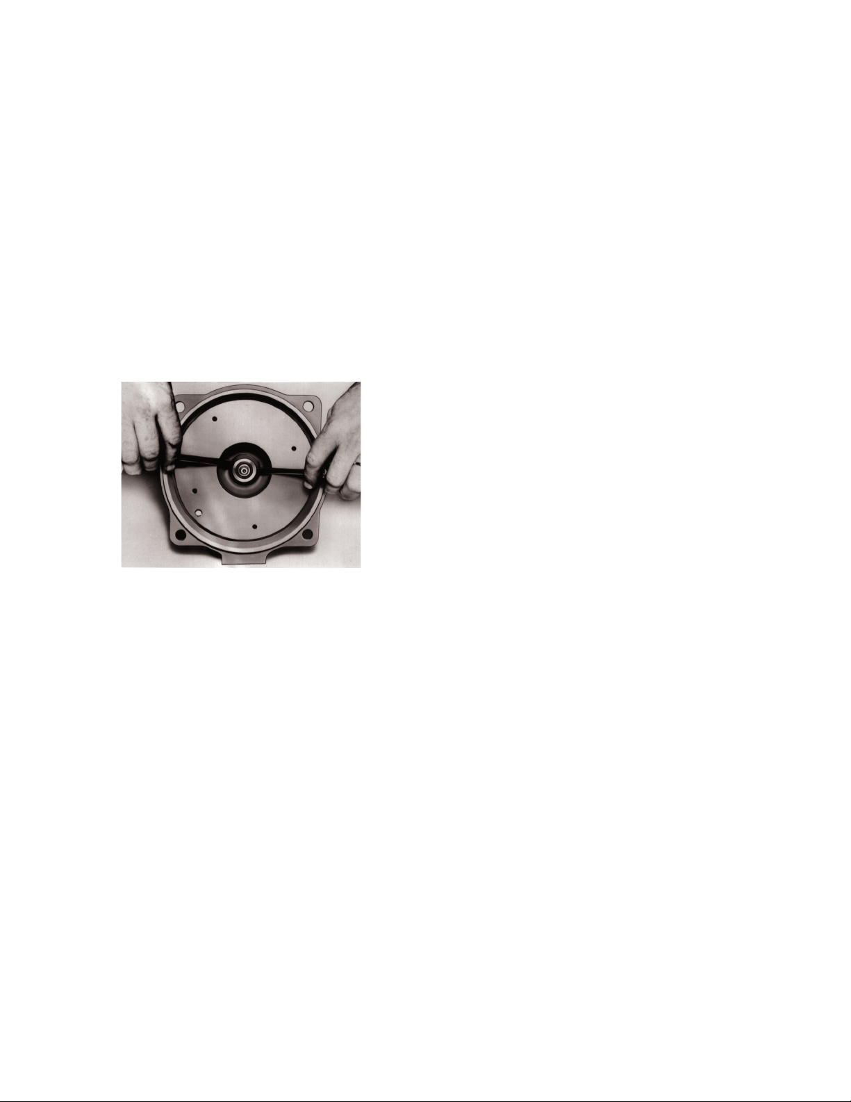
8. Pry off rotating member of mechanical seal
from shaft by using two (2) screwdrivers
(Fig. 1).
Figure 1
with LOCQUIC®, Primer “T” - Loctite® product
Item No. 74756. (Purchase at Automotive
Parts or Hardware). Let parts dry and then
apply Loctite® #271 on same parts.
6. Hold shaft from rotating as described in
paragraph 7 of Dismantling. Thread impeller
on shaft until it is tight against shaft
shoulder.
7. Apply locking compound and replace
impeller nut. Hold impeller from rotating as
indicated in paragraph 6 of dismantling.
8. Remove burrs caused by screwdriver on
periphery of impeller in waterway passages.
9. Replace motor and rotating element in
casing. Be sure to install new gasket.
10. Tighten casing bolts alternately and evenly.
11. Replace hold-down bolts.
12. Check for free rotation after assembly is
complete.
13. Replace hold-down bolts.
14. Close all drain openings. Use pipe joint
compound on male threads.
15. Reprime before starting. Do not start unit
until pump is completely filled with water.
9. Remove bolts holding adapter to motor.
10. Place adapter on a flat surface. Push out
stationary parts of mechanical seal (seat and
rubber mounting cup).
B) Reassembly:
1. Clean gasket and flange faxes, male and
female locks, seal seat counterbore and shaft,
and in particular the shaft shoulder fitting
against impeller.
2. Lube counterbore of adapter and rubber
bushing of stationary seal with water or light
oil. Press stationary seat in counterbore
squarely and evenly. Caution: Do not mar the
lapped face of seat.
3. Remount adapter on motor. Make sure motor
shaft does not dislocate stationary seat of
the seal.
4. Apply a thin coat of light oil or water to
motor shaft and the rubber seal member of
seal. Slide rotating member of mechanical
seal on motor shaft. Be sure rotating seal face
stays in holding collar during installation.
Take extra care not to damage the seal
lapped faces.
5. Spray both shaft and metal impeller threads
4
Page 5

This warranty applies to all water systems pumps manufactured by Red Jacket Water Products.
Any part or parts found to be defective within the warranty period shall be replaced at no charge to the dealer during the warranty period. The war-
ranty period shall exist for a period of twelve (12) months from date of installation or eighteen (18) months from date of manufacture, whichever
period is shorter.
A dealer who believes that a warranty claim exists must contact the authorized Red Jacket Water Products distributor from whom the pump was
purchased and furnish complete details regarding the claim. The distributor is authorized to adjust any warranty claims utilizing the Red Jacket Water
Products Customer Service Department.
The warranty excludes:
(a) Labor, transportation and related costs incurred by the dealer;
(b) Reinstallation costs of repaired equipment;
(c) Reinstallation costs of replacement equipment;
(d) Consequential damages of any kind; and,
(e) Reimbursement for loss caused by interruption of service.
For purposes of this warranty, the following terms have these definitions:
(1) “Distributor” means any individual, partnership, corporation, association, or other legal relationship that stands between Red Jacket Water Products
and the dealer in purchases, consignments or contracts for sale of the subject pumps.
(2) “Dealer” means any individual, partnership, corporation, association, or other legal relationship which engages in the business of selling or leasing
pumps to customers.
(3) “Customer” means any entity who buys or leases the subject pumps from a dealer. The “customer” may mean an individual, partnership, corpora-
tion, limited liability company, association or other legal entity which may engage in any type of business.
THIS WARRANTY EXTENDS TO THE DEALER ONLY.
RED JACKET WATER PRODUCTS LIMITED WARRANTY
Xylem, Inc.
2881 East Bayard Street Ext., Suite A
Seneca Falls, NY 13148
Phone: (866) 325-4210
Fax: (888) 322-5877
www.xyleminc.com/brands/redjacketwaterproducts
Red Jacket Water Products is a trademark of Xylem Inc. or one of its subsidiaries.
© 2012 Xylem Inc. IM138 Revision Number 1 July 2012
5
Page 6

MANUAL DE INSTRUCCIÓN
IM138
HMC
Bomba centrífuga de acoplamiento cerrado
INSTRUCCIONES DE INSTALACIÓN, FUNCIONAMIENTO Y MANTENIMIENTO
6
Page 7

Índice
Índice
TEMA PÁGINA
Información importante ..............................................................................................................................................8
Instalación ................................................................................................................................................................... 8
Operación ...................................................................................................................................................................8
Mantenimiento ............................................................................................................................................................9
Garantía limitada de Red Jacket Water Products ........................................................................................................ 10
7
Page 8

IMPORTANTE
IMPORTANTE
A. Inspeccione la unidad para determinar si resultó dañada
durante el envío. Notifique cualquier daño a la compañía
de transporte de inmediato.
B. El suministro eléctrico debe ser un circuito derivado sepa-
rado con fusibles o cortacircuitos y tamaños de alambre
de acuerdo con los códigos eléctricos nacionales y locales.
C. SIEMPRE desconecte el suministro eléctrico cuando
maneje la bomba o los controles. Instale un desconectador de todos los circuitos, cerca de la bomba.
d. Los motores deben cablearse para la tensión apropiada.
(CONSULTE LA PLACA DEL FABRICANTE). El tamaño del alambre debe limitar la caída de tensión al 10% de
la tensión de la placa del fabricante en los terminales del
motor; de lo contrario se reducirá la vida útil del motor y
disminuirá el rendimiento de la bomba.
E. Monofásica: A veces la protección térmica para unidades
monofásicas está incorporada (CONSULTE LA PLACA
DEL FABRICANTE). Si no se proporciona protección
incorporada, utilice un contactador con una sobrecarga
apropiada. Se permite instalar fusibles siempre que sean
los adecuados.
F. Trifásica: Proporcione protección de tres circuitos deriva-
dos con arrancador magnético del tamaño adecuado.
G. Temperaturas máximas del líquido: HSC y 3673 ajusta-
dos con plástico, 180º F (82º) máximo. 3642-36563673, AI, BF, AB, 212º F (100º C) con sello de alta
temperatura opcional.
H. La inspección y el mantenimiento regulares prolongarán
la vida de servicio. Base la programación en el tiempo de
operación.
de manera que no se produzca deformación o esfuerzo al
apretar los pernos. Las bombas son de funcionamiento silencioso y suave, pero se recomienda instalar una montura de
caucho sobre los cimientos susceptibles a los efectos sonoros.
Alineamiento – El alineamiento fino no es necesario ya que
las bombas son de acoplamiento cerrado.
Conexiones – Deben ser de acuerdo con el Código Eléctrico
de EE.UU. y los códigos locales. El circuito derivado del
motor debe protegerse con un arrancador manual o magnético adecuado. Se deben seleccionar los fusibles y retardo
de tiempo apropiados para el arranque, de acuerdo con los
códigos. Se recomienda protección contra la baja tensión.
Los motores monofásicos son de doble tensión - 115/230
voltios, 60 Hz, de C.A. Todas las bombas se someten a
prueba en la fábrica. Durante la instalación, se debe comprobar la rotación correcta (unidades trifásicas), fase, frecuencia
y tensión de la fuente de alimentación. Las líneas de energía
deben ser del tamaño apropiado para conducir la corriente.
Los motores monofásicos de 3 HP son de doble tensión 115/230 voltios, 60 Hz, de C.A. Los motores monofásicos
de 5 HP son de 230 V, 60 Hz, C.A. Todos los demás motores son trifásicos, de doble tensión - 230/460 voltios, 60
Hz, de C.A. Se recomiendan las tensiones altas cuando estén
disponibles. La rotación trifásica debe ser verificada en el
momento de la instalación. Cierre y luego abra los contactos
rápidamente, observando la rotación de la sección expuesta
de las partes giratorias. La rotación debe concordar con la
flecha en la carcasa de la bomba. La rotación estándar es en
sentido contrahorario cuando se observa desde el extremo
de succión. Las conexiones del motor pueden cambiarse en
el campo siguiendo el diagrama de conexiones dentro de la
tapa de la caja de terminales o en la placa del fabricante del
motor.
INSTALACIÓN
INSTALACIÓN
Ubicación – Sitúe la bomba lo más cerca de la fuente de
líquido que sea práctico (por debajo del nivel de almacenaje
de líquido si se considera la operación automática). Proteja
la unidad contra los daños causados por el tiempo frío y el
agua debido a inundación. Se desea una elevación estática
baja y tuberías de succión y de descarga cortas y directas.
Para una elevación de succión de más de 15 pies, consulte
la curva de rendimiento de la bomba con respecto a la carga
de succión positiva neta requerida (NPSHR). La tubería de
succión debe ser al menos del mismo tamaño que la conexión de succión de la bomba, e inclinarse hacia arriba a la
bomba para evitar las bolsas de aire. Si se utiliza una tubería
más grande que la succión de la bomba, debe instalarse un
reductor de tubo excéntrico en la bomba. Se requiere una
válvula de compuerta en la succión sólo en una instalación
de carga de succión positiva y no debe usarse para estrangular la bomba.
Deje un espacio adecuado para el mantenimiento y la ventilación.
Cimiento – Emperne la unidad al cimiento para facilitar el
desmantelamiento. La superficie del cimiento debe ser plana,
OPERACIÓN
OPERACIÓN
Llene la tubería de succión y la carcasa con el líquido que
se va a bombear para asegurar que el sello mecánico no
funcione en seco. Se proporcionan cuatro tapones en la carcasa. En cualquier posición, un tapón estará en el extremo
superior para cebar y/o ventear, y otro en el extremo inferior
para drenar. Con la bomba cebada y el motor conectado
correctamente, puede arrancarse la unidad. Asegúrese de
que la bomba no sea puesta en marcha contra una válvula
cerrada en la tubería de descarga. La limitación de temperatura máxima (212º F) es impuesta por el material del sello
mecánico. Se ofrecen sellos de alta temperatura opcionales.
8
Page 9

MANTENIMIENTO
MANTENIMIENTO
1. Lubricación
Las bombas no requieren mantenimiento.
Los motores utilizan rodamientos de doble blindaje,
prelubricados para toda la vida útil de los mismos. No se
requiere lubricación adicional.
2. Reemplazo del sello mecánico
A) Desmantelamiento:
1. Apague el suministro eléctrico.
2. Drene el sistema.
3. Quite los pernos que sujetan el adaptador para
el motor al cimiento.
4. Quite los pernos de la carcasa.
5. Retire el motor y el elemento giratorio de
la carcasa, dejando la carcasa y tubería inalteradas.
6. Introduzca un destornillador en el pasaje de agua
del impulsor. Quite la tuerca del impulsor con una
llave de cubo (5⁄8 pulg. en las secciones planas).
7. Retire el impulsor del eje de la siguiente manera:
a) Motores Franklin:
Retire la tapa del extremo del eje del motor.
Introduzca un destornillador en la ranura del
eje del motor. Sujetando el eje para que no gire,
destornille el impulsor del eje girando en sentido
contrahorario cuando esté de frente al mismo.
Para aflojar los impulsores metálicos y trifásicos,
utilice un soplete para aplicar calor a la rosca del
eje expuesto y al cubo del impulsor, ya que se
empleó compuesto fijador para sujetar el impulsor en posición.
b) Motores A.O. Smith:
Retire la tapa del extremo del motor. Introduzca
una llave de boca de 7⁄16 pulg. debajo del mecanismo del interruptor en las secciones planas
sobre el eje del motor. Sujetando el eje para que
no gire, destornille el impulsor del eje. Podría ser
necesario aplicar calor, tal como se indicó en 7a.
8. Retire la sección giratoria del sello mecánico del
eje con dos (2) destornilladores (Fig. 1).
Figura 1
9. Quite los pernos que sujetan el adaptador al motor.
10. Coloque el adaptador sobre una superficie plana.
Empuje hacia afuera las partes estacionarias del sello
mecánico (asiento y tazón de montaje de caucho).
B) Reensamble:
1. Limpie las caras de la empaquetadura y brida,
los cierres macho y hembra, el
ensanchamiento del asiento del sello y el eje, y
en particular el reborde del eje que calza
contra el impulsor.
2. Lubrique el ensanchamiento del adaptador y
el buje de caucho del sello estacionario con
agua y aceite liviano. Oprima el asiento
estacionario en el ensanchamiento en forma
encuadrada y pareja. Precaución: No estropee
la cara pulida del asiento.
3. Monte nuevamente el adaptador sobre
el motor. Asegúrese de que el eje del motor no
desplace el asiento estacionario del sello.
4. Aplique una capa delgada de aceite liviano o
agua al eje del motor y el componente de
caucho del sello. Deslice el componente
rotatorio del sello mecánico sobre el eje del
motor. Asegúrese de que la cara del sello
rotatorio se mantenga en el interior, sujetando
el collar durante la instalación. Tenga cuidado
de no dañar las caras pulidas del sello.
5. Rocíe las roscas del eje y del impulsor metálico
con LOCQUIC®, Primer “T”—Loctite®, Nº de
producto 74756. (Puede adquirirse en una
tienda de partes automotrices o en una
ferretería). Deje las partes secar y luego
aplique Loctite® #271 sobre las mismas partes.
6. Sujete el eje para que no gire, tal como se
describió en el párrafo 7 de la sección de
Desmantelamiento. Atornille el impulsor en
el eje hasta que quede ajustado contra el
reborde del eje.
7. Aplique compuesto fijador y reemplace la
tuerca del impulsor. Sujete el impulsor para
que no gire, tal como se describió en el párrafo
6 de la sección de Desmantelamiento.
8. Quite las rebabas en la periferia del impulsor,
en los pasajes de agua con un destornillador.
9. Reinstale el motor y el elemento rotatorio en
la carcasa. Asegúrese de instalar una
empaquetadura nueva.
10. Apriete los pernos de la carcasa en forma
alterna y pareja.
11. Reinstale los pernos de sujeción.
12. Verifique que el conjunto gire libremente
después de finalizar el ensamble.
13. Reinstale los pernos de sujeción.
14. Cierre todos los orificios de drenaje. Utilice
compuesto para juntas de tubería sobre las
roscas macho.
15. Recebe antes de arrancar. No arranque la
bomba hasta que esté completamente llena
con agua.
9
Page 10

GARANTÍA LIMITADA DE RED JACKET WATER PRODUCTS
Esta garantía es aplicable a todas las bombas para sistemas de agua fabricadas por Red Jacket Water Products.
Toda parte o partes que resultaren defectuosas dentro del período de garantía serán reemplazadas durante dicho período de garantía sin cargo para el
comerciante. Tal período de garantía se extiende por doce (12) meses a partir de la fecha de instalación, o dieciocho (18) meses a partir de la fecha de
fabricación, la que se cumpla primero.
El comerciante que considere que existe lugar a un reclamo de garantía deberá ponerse en contacto con el distribuidor autorizado de Red Jacket Water
Products del cual adquiriera la bomba y brindar información detallada con respecto al reclamo. El distribuidor está autorizado a liquidar todos los
reclamos por garantía a través del Departamento de Servicios a Clientes de Red Jacket Water Products.
La presente garantía excluye:
(a) La mano de obra, el transporte y los costos relacionados en los que incurra el comerciante;
(b) los costos de reinstalación del equipo reparado;
(c) los costos de reinstalación del equipo reemplazado;
(d) daños emergentes de cualquier naturaleza; y
(e) el reembolso de cualquier pérdida causada por la interrupción del servicio.
A los fines de esta garantía, los términos “Distribuidor”, “Comerciante” y “Cliente” se definen como sigue:
(1) “Distribuidor” es aquel individuo, sociedad, corporación, asociación u otra entidad jurídica que opera entre Red Jacket Water Products y el comer-
ciante para la compra, consignación o contratos de venta de las bombas en cuestión.
(2) “Comerciante” es todo individuo, sociedad, corporación asociación u otra entidad jurídica que realiza negocios de venta o alquiler-venta (leasing)
de bombas a los clientes.
(3) “Cliente” es toda entidad que compra o adquiere bajo la modalidad de leasing las bombas en cuestión de un comerciante. El término “cliente”
puede significar un individuo, sociedad, corporación, sociedad de responsabilidad limitada, asociación o cualquier otra entidad jurídica con actividades en cualquier tipo de negocios.
LA PRESENTE GARANTÍA SE EXTIENDE AL COMERCIANTE ÚNICAMENTE.
Xylem, Inc.
2881 East Bayard Street Ext., Suite A
Seneca Falls, NY 13148
Teléfono: (866) 325-4210
Fax: (888) 322-5877
www.xyleminc.com/brands/redjacketwaterproducts
Red Jacket Water Products son una marca registrada de Xylem Inc. o una de sus filiales.
© 2012 Xylem Inc. IM138 Revisión Número 1 Julio 2012
Page 11

MANUEL D'UTILISATION
IM138
HMC
Pompe centrifuge montée sur moteur
DIRECTIVES D’INSTALLATION, D’UTILISATION ET D’ENTRETIEN
Page 12

Table des matières
Table des matières
SUJET PAGE
Informations importantes .......................................................................................................................................... 13
Installation ................................................................................................................................................................13
Utilisation ..................................................................................................................................................................13
Entretien ...................................................................................................................................................................14
Garantie limitée de Red Jacket Water Products .......................................................................................................... 16
12
Page 13

INFORMATIONS IMPORTANTES
INFORMATIONS IMPORTANTES
A. Inspecter l’appareil pour s’assurer qu’il n’a pas
été endommagé pendant le transport. Signaler
immédiatement tout dommage au transporteur.
B. L’alimentation électrique doit être assurée par un circuit
de dérivation distinct dont les fusibles ou les disjoncteurs,
le calibre des fils, etc. sont conformes aux prescriptions
du code provincial ou national de l’électricité.
C. On doit TOUJOURS couper le courant lorsque l’on
effectue quelque travail que ce soit sur la pompe ou les
commandes. Poser un sectionneur tout conducteur près
de la pompe.
D. Le câblage d’alimentation du moteur doit convenir
à la tension de fonctionnement (VOIR LA PLAQUE
SIGNALÉTIQUE DU MOTEUR). Les fils doivent
avoir un calibre limitant la chute de tension maximale,
aux bornes du moteur, à 10 % de la valeur de tension
indiquée sur la plaque signalétique, sinon la durée de vie
du moteur et les performances de la pompe diminueront.
E. Moteurs monophasés — ces moteurs sont parfois munis
d’une protection thermique intégrée (VOIR LA PLAQUE
SIGNALÉTIQUE). Dans le cas contraire, utiliser un
contacteur à protection appropriée contre les surcharges.
Les dispositifs fusibles sont admissibles s’ils offrent une
protection adéquate.
F. Moteurs triphasés — employer une protection trois
conducteurs appropriée et un démarreur magnétique
convenant à la charge électrique.
G. Température maximale du liquide — HSC et 3673
avec composants en plastique : 82 °C (180 °F) — 36423656-3673, AI, BF, AB : 100 °C (212 °F), avec garniture
mécanique optionnelle pour hautes températures.
H. Un programme d’inspection et d’entretien réguliers basé
sur le temps de fonctionnement augmentera la durée de
vie de l’appareil.
INSTALLATION
INSTALLATION
Emplacement — Placer la pompe aussi près de la source
de liquide que possible (au-dessous du niveau du liquide
si l’on veut que la pompe fonctionne automatiquement).
Protéger l’appareil contre le froid et les inondations. Une
hauteur géométrique d’aspiration réduite et une tuyauterie
d’aspiration et de refoulement directe et courte sont
souhaitables. Pour les hauteurs d’aspiration de plus de
15 pi, utiliser la hauteur nette d’aspiration requise (NPSHR)
indiquée sur la courbe de performances de la pompe. La
tuyauterie d’aspiration doit avoir un calibre au moins égal
à celui du raccord d’aspiration de la pompe, ainsi qu’une
inclinaison vers le haut depuis la source de liquide jusqu’à
la pompe pour prévenir les poches d’air. S’il faut un calibre
plus gros, on doit installer un raccord réducteur excentré
à la pompe. On doit poser un robinet-vanne sur le tuyau
d’aspiration seulement quand la hauteur totale de charge
à l’aspiration est positive, mais ne pas employer ce robinet
pour réduire la section de passage vers la pompe.
Surface portante — Assujettir la pompe à la surface portante
avec des boulons d’ancrage pour en faciliter le démontage.
La surface portante doit être plane pour prévenir toute
contrainte ou déformation due au serrage des boulons. La
pompe a un fonctionnement régulier et silencieux, mais
on recommande de la monter sur caoutchouc si la surface
portante résonne.
Alignement — Aucun alignement n’est requis étant donné
que la pompe est montée sur moteur.
Câblage — Il faut se conformer aux prescriptions du
code provincial ou national de l’électricité. Le circuit de
dérivation alimentant le moteur doit être protégé par un
démarreur manuel ou magnétique. Les dispositifs fusibles et
de démarrage temporisés doivent être conformes au code. Il
est recommandé d’utiliser une protection contre les basses
tensions.
Les moteurs monophasés sont bitension (115/230 V c.a.,
60 Hz). Chaque pompe est mise à l’essai en usine. S’il s’agit
d’une pompe à moteur triphasé, on doit en vérifier le sens
de rotation durant l’installation, ainsi que le nombre de
phases, la fréquence et la tension du courant d’alimentation.
Les lignes électriques doivent avoir le calibre approprié à
l’intensité de courant.
Les moteurs monophasés de 3 hp sont bitension
(115/230 V c.a., 60 Hz), et ceux de 5 hp fonctionnent en
230 V c.a., 60 Hz. Tous les autres sont triphasés et bitension
(230/460 V c.a., 60 Hz). La tension la plus haute est
recommandée dans la mesure du possible.
Pour vérifier le sens de rotation des pompes à moteur
triphasé, mettre et couper le courant immédiatement tout
en observant l’une des pièces tournantes. Le sens de rotation
approprié est antihoraire, vu du côté aspiration, comme
l’indique la flèche sur le corps de pompe. On peut modifier
le câblage selon le schéma de câblage figurant sur la plaque
signalétique du moteur ou à l’intérieur du couvercle de la
boîte à bornes.
UTILISATION
UTILISATION
Remplir la tuyauterie d’aspiration et le corps de pompe de
liquide à pomper pour s’assurer que la garniture mécanique
ne sera pas utilisée à sec. Quatre bouchons sont montés sur
le corps de pompe pour qu’il y en ait toujours un en haut
pour le remplissage et la mise à l’air libre et un autre en
bas pour la vidange, peu importe la position de montage
de la pompe. Une fois le moteur câblé correctement et la
tuyauterie et le corps de pompe remplis, on peut mettre la
pompe en service. S’assurer qu’il n’y a aucun robinet fermé
sur la tuyauterie de refoulement au moment du démarrage.
Les matériaux de la garniture mécanique standard limitent
la température maximale du liquide à 100 °C (212 °F), mais
des garnitures mécaniques pour hautes températures sont
offertes en option.
Prévoir assez d’espace autour de la pompe pour l’entretien et
l’aération.
13
Page 14

ENTRETIEN
ENTRETIEN
1. Lubrification
Les pompes ne devraient pas requérir d’entretien.
Les roulements à billes du moteur sont à double flasque
et à graissage permanent. Ils ne nécessitent donc aucune
lubrification.
2. Remplacement de la garniture mécanique
A. Démontage
1. Couper le courant.
2. Vidanger le système.
3. Déposer les boulons d’ancrage de l’adaptateur de
moteur à la surface portante.
4. Enlever les vis du corps de pompe
5. Séparer l’ensemble moteur-éléments de pompage
mobiles d’avec le corps de pompe, sans détacher
celui-ci ni la tuyauterie.
6. Insérer un tournevis dans un passage de roue pour
immobiliser celle-ci, puis déposer l’écrou de
blocage de roue avec une clé à douilles de 5⁄8 po.
7. Enlever la roue de l’arbre comme suit :
a) Moteurs Franklin
Ôter l’obturateur de bout d’arbre du moteur.
Insérer un tournevis dans la fente de l’arbre
et immobiliser celui-ci, puis dévisser (sens
antihoraire, face à la roue) la roue. S’il s’agit
d’une roue en métal ou de pompe à moteur
triphasé, chauffer les filets et le moyeu de roue au
chalumeau pour amollir l’enduit frein des filets et
dévisser la roue.
b) Moteurs A.O. Smith
Déposer le couvercle d’extrémité du moteur.
Bloquer l’arbre par ses méplats (sous le
mécanisme interrupteur) avec une clé ouverte de
7
⁄16 po, puis dévisser la roue. Au besoin, chauffer
les filets et le moyeu de roue (v. 7 a ci-dessus).
8. Extraire l’élément mobile de la garniture
mécanique (fig. 1) avec deux (2) tournevis utilisés
comme leviers.
Figure 1
9. Enlever les vis retenant l’adaptateur de moteur
au moteur.
10. Placer le côté pompe de l’adaptateur de moteur sur
une surface plane, puis, par l’autre côté, pousser
l’élément fixe (bague et coupelle de caoutchouc)
de la garniture mécanique hors de son logement
(siège).
B. Remontage
1. Nettoyer les surfaces de guidage, de contact,
d’épaulement et d’étanchéité des brides, des sièges
et de l’arbre.
2. Avec de l’eau ou une huile légère, lubrifier le
caoutchouc de l’élément fixe de la garniture
mécanique ainsi que les surfaces de son siège, puis
pousser l’élément fixe uniformément jusqu’au fond
du siège. Prendre garde de ne pas abîmer les
surfaces du siège et de l’élément fixe.
3. Reposer l’adaptateur sur le moteur en s’assurant
que l’arbre de moteur ne déloge pas l’élément fixe
de son siège.
4. Enduire d’un peu d’eau ou d’huile légère l’arbre de
moteur et le caoutchouc de l’élément mobile de la
garniture mécanique. Enfiler l’élément mobile sur
l’arbre. S’assurer que la surface d’étanchéité de la
garniture reste dans son collier de retenue pendant
la pose et veiller particulièrement à ne pas abîmer
les surfaces de la garniture.
5. Pulvériser de l’apprêt Primer T de LOCQUICMD
(produit LoctiteMD no 74756, vendu dans les
magasins de pièces d’automobile et les
quincailleries) sur les filets de l’arbre et de la roue
en métal et le laisser sécher. Enduire ensuite les
mêmes filets de LoctiteMD no 271.
6. Immobiliser l’arbre (v. 7 a et 7 b ci-dessus) et y
visser la roue à fond.
7. Appliquer de l’enduit frein sur les filets de
l’écrou de blocage de roue, puis poser celui-ci tout
en immobilisant la roue (v. paragr. 6 sous
Démontage).
8. Enlever toute barbe produite par le tournevis du
côté extérieur du passage de roue utilisé.
9. Joindre l’ensemble moteur-éléments de pompage
mobiles au corps de pompe. Voir à utiliser un joint
d’étanchéité neuf.
10. Poser et serrer les vis du corps de pompe
uniformément et tour à tour.
11. Reposer les boulons d’ancrage.
12. Une fois le remontage terminé, vérifier si la roue
tourne librement.
13. Après en avoir enduit les filets de pâte à joints,
poser un bouchon sur tout orifice non obturé du
corps de pompe, sauf l’orifice d’amorçage.
14. Amorcer la pompe avant de la mettre en service.
Ne pas la mettre en marche tant qu’elle n’est pas
pleine d’eau.
14
Page 15

NOTES/NOTAS
NOTES/NOTAS
15
Page 16

GARANTIE LIMITÉE DE RED JACKET WATER PRODUCTS
La présente garantie s’applique à chaque pompe de système d’alimentation en eau fabriquée par Red Jacket Water Products.
Toute pièce se révélant défectueuse sera remplacée sans frais pour le détaillant durant la période de garantie suivante expirant la première : douze (12)
mois à compter de la date d’installation ou dix-huit (18) mois à partir de la date de fabrication.
Le détaillant qui, aux termes de cette garantie, désire effectuer une demande de règlement doit s’adresser au distributeur Red Jacket Water Products agréé
chez lequel la pompe a été achetée et fournir tous les détails à l’appui de sa demande. Le distributeur est autorisé à régler toute demande par le biais du
service à la clientèle de Red Jacket Water Products.
La garantie ne couvre pas :
a) les frais de main-d’œuvre ni de transport ni les frais connexes encourus par le détaillant ;
b) les frais de réinstallation de l’équipement réparé ;
c) les frais de réinstallation de l’équipement de remplacement ;
d) les dommages indirects de quelque nature que ce soit ;
e) ni les pertes découlant de la panne.
Aux fins de la présente garantie, les termes ci-dessous sont définis comme suit :
1) « Distributeur » signifie une personne, une société de personnes, une société de capitaux, une association ou autre entité juridique servant
d’intermédiaire entre Red Jacket Water Products et le détaillant pour les achats, les consignations ou les contrats de vente des pompes en question.
2) « Détaillant » veut dire une personne, une société de personnes, une société de capitaux, une association ou autre entité juridique dont les activités
commerciales sont la vente ou la location de pompes à des clients.
3) « Client » signifie une entité qui achète ou loue les pompes en question chez un détaillant. Le « client » peut être une personne, une société de personnes, une société de capitaux, une société à responsabilité limitée, une association ou autre entité juridique se livrant à quelque activité que ce soit.
CETTE GARANTIE SE RAPPORTE AU DÉTAILLANT SEULEMENT.
Xylem, Inc.
2881 East Bayard Street Ext., Suite A
Seneca Falls, NY 13148
Téléphone: (866) 325-4210
Télécopie: (888) 322-5877
www.xyleminc.com/brands/redjacketwaterproducts
Red Jacket Water Products est une marque déposée de Xylem Inc. ou d'une de ses filiales.
© 2012, Xylem Inc. IM138 Révision numéro 1 Juillet 2012
 Loading...