

Page 1

Variable Speed
Pump Control
Installation Programming & Operation
Models covered:
All AV2 Model
AQUAVAR
II
Controllers
software revision 120
AQUAVAR
®
AV II
IM131R01
U
®
L
Page 2

Page 3

2
AQUAVAR
II Controller Model
_________________ Transducer Model_______________________
AQUAVAR
II Serial Number
_________________ Transducer Rating_______________________
Date purchased _________________
Purchased from _________________
Pump Model _________________ Software Version _______________________
Pump Code Number _________________
Program Record
Please use the following to record the final values programmed into the AQUAVAR controller after installation.
Required Value____________________ (select) Level 2____________________________ (%)
Autostart________________________ (on/off) Intensity 1 _________________________ (%)
Password ________________________ (value) Intensity 2 _________________________ (%)
Window ___________________________ (%) Pressure Increase ___________________ (PSI)
Ramp Hysteresis _____________________ (%) Pressure Decrease___________________ (PSI)
Ramp 1 _______________________ (seconds) Enable Sequence Control______________ (Hz)
Ramp 2 _______________________ (seconds) Switch Interval ___________________ (hours)
Ramp 3 _______________________ (seconds) Optional Value_________________________
Ramp 4 _______________________ (seconds) Synchron Limit _____________________ (Hz)
Max. Frequency _____________________ (Hz) Sychron Window____________________ (Hz)
Min. Frequency______________________ (Hz) Pump Address _________________ (# or off)
Config. F Min. __________ (F –>0/F –>F min.) ADC Reference ___________________ (select)
Stop - Delay F Min._______________ (seconds) Freq. Lifting ________________________ (Hz)
Sensor Adjust _______________ (out of range) Lift Intensity________________________ (%)
Sensor Curve _____________ (linear/quadratic) Analog out______________________ (select)
Sensor Range - 20mA=362.6 __________ (PSI) Pressure Unit ____________________ (select)
Mode ___________________________ (select) Test Run After __________________ (in hours)
(actuator/controller/multicontroller/synch.) Test Frequency______________________ (Hz)
Regulation Mode_________________ (normal) Conveyor Limit _____________________ (PSI)
Start Value_________________________ (PSI) Delay Time ____________________ (seconds)
Config. Second Value _________________ (off) Error Reset______________________ (on/off)
Relay Config.__________________ (run motor) Display Contrast_____________________ (%)
Offset Input____________________________ Lock Function____________________ (on/off)
Level 1 ____________________________ (%)
AQUAVAR
II
Controller Owner’s Information Record
Page 4

3
Index
System Design . . . . . . . . . . . . . . . . . . . . . . . . . . . . . . . . . . . . . . . . . . . . . . . . . . 5
Important Safety Instructions . . . . . . . . . . . . . . . . . . . . . . . . . . . . . . . . . . . . . 6
Installation Procedures . . . . . . . . . . . . . . . . . . . . . . . . . . . . . . . . . . . . . . . . . . . 9
Materials Checklist . . . . . . . . . . . . . . . . . . . . . . . . . . . . . . . . . . . . . . . . . . . . . . 9
1. Mounting the AQUAVARII Controller . . . . . . . . . . . . . . . . . . . . . . . . . . . . . . . 10
2. Electrical Connections . . . . . . . . . . . . . . . . . . . . . . . . . . . . . . . . . . . . . . . . 12
3. Pump Priming . . . . . . . . . . . . . . . . . . . . . . . . . . . . . . . . . . . . . . . . . . . . . . 28
4. Run Test . . . . . . . . . . . . . . . . . . . . . . . . . . . . . . . . . . . . . . . . . . . . . . . . . . 28
Programming . . . . . . . . . . . . . . . . . . . . . . . . . . . . . . . . . . . . . . . . . . . . . . . . . . 31
1. The Main Menu - Setting One Pump Constant Pressure . . . . . . . . . . . . . . . . 31
2. Single Pump - Pump Protection . . . . . . . . . . . . . . . . . . . . . . . . . . . . . . . . . 33
• To Set Run-Out Protection . . . . . . . . . . . . . . . . . . . . . . . . . . . . . . . . . . . 34
• To Set Low/No Flow Protection . . . . . . . . . . . . . . . . . . . . . . . . . . . . . . . . 34
3. Single Pump - System Curve Compensation . . . . . . . . . . . . . . . . . . . . . . . . 38
• Entering Compensation Values . . . . . . . . . . . . . . . . . . . . . . . . . . . . . . . . 39
• Circulator Applications . . . . . . . . . . . . . . . . . . . . . . . . . . . . . . . . . . . . . . 41
4. Single Pump Constant Flow . . . . . . . . . . . . . . . . . . . . . . . . . . . . . . . . . . . . 41
5. Single Pump - Level Control Applications . . . . . . . . . . . . . . . . . . . . . . . . . . 43
6. Single Pump - Submersible . . . . . . . . . . . . . . . . . . . . . . . . . . . . . . . . . . . . 44
7. Setting a Second Required Value . . . . . . . . . . . . . . . . . . . . . . . . . . . . . . . . 46
8. Variable Second Required Value . . . . . . . . . . . . . . . . . . . . . . . . . . . . . . . . . 48
9. Multiple Pump Constant Pressure and System Curve Compensation . . . . . . . 53
• Synchronous Control . . . . . . . . . . . . . . . . . . . . . . . . . . . . . . . . . . . . . . . 56
10. Multiple Pump - Pump Protection . . . . . . . . . . . . . . . . . . . . . . . . . . . . . . . . 59
• To Set Low/No Flow Protection . . . . . . . . . . . . . . . . . . . . . . . . . . . . . . . . 59
Operator Custom Features and Displays . . . . . . . . . . . . . . . . . . . . . . . . . . . . 61
• Jog Mode . . . . . . . . . . . . . . . . . . . . . . . . . . . . . . . . . . . . . . . . . . . . . . . . . 61
•Window . . . . . . . . . . . . . . . . . . . . . . . . . . . . . . . . . . . . . . . . . . . . . . . . . . 61
• Ramp Hysteresis . . . . . . . . . . . . . . . . . . . . . . . . . . . . . . . . . . . . . . . . . . . . 61
• Ramp Settings . . . . . . . . . . . . . . . . . . . . . . . . . . . . . . . . . . . . . . . . . . . . . 61
• Ramp 1-4 . . . . . . . . . . . . . . . . . . . . . . . . . . . . . . . . . . . . . . . . . . . . . . . . . 62
• Maximum Frequency . . . . . . . . . . . . . . . . . . . . . . . . . . . . . . . . . . . . . . . . . 62
• Minimum Frequency . . . . . . . . . . . . . . . . . . . . . . . . . . . . . . . . . . . . . . . . . 63
• Config. F Min . . . . . . . . . . . . . . . . . . . . . . . . . . . . . . . . . . . . . . . . . . . . . . 63
• Stop-Delay F Min . . . . . . . . . . . . . . . . . . . . . . . . . . . . . . . . . . . . . . . . . . . 63
• Sensor Adjustment . . . . . . . . . . . . . . . . . . . . . . . . . . . . . . . . . . . . . . . . . . 63
• Sensor Curve . . . . . . . . . . . . . . . . . . . . . . . . . . . . . . . . . . . . . . . . . . . . . . 63
• Mode . . . . . . . . . . . . . . . . . . . . . . . . . . . . . . . . . . . . . . . . . . . . . . . . . . . . 63
• Start Value . . . . . . . . . . . . . . . . . . . . . . . . . . . . . . . . . . . . . . . . . . . . . . . . 64
• Config. Required Value 2 . . . . . . . . . . . . . . . . . . . . . . . . . . . . . . . . . . . . . . 64
• Relay Config. . . . . . . . . . . . . . . . . . . . . . . . . . . . . . . . . . . . . . . . . . . . . . . 64
• Submenu Offset . . . . . . . . . . . . . . . . . . . . . . . . . . . . . . . . . . . . . . . . . . . . 64
• Regulation Mode . . . . . . . . . . . . . . . . . . . . . . . . . . . . . . . . . . . . . . . . . . . 64
• Submenu Sequence Control . . . . . . . . . . . . . . . . . . . . . . . . . . . . . . . . . . . . 65
• Actual Value Increase . . . . . . . . . . . . . . . . . . . . . . . . . . . . . . . . . . . . . . . . 65
Index
!
▼
▼
Page 5

Index (continued)
Operator Custom Features and Displays (continued)
• Actual Value Decrease . . . . . . . . . . . . . . . . . . . . . . . . . . . . . . . . . . . . . . . . 65
• Enable Sequence Control . . . . . . . . . . . . . . . . . . . . . . . . . . . . . . . . . . . . . . 65
• Switch Interval . . . . . . . . . . . . . . . . . . . . . . . . . . . . . . . . . . . . . . . . . . . . . 65
• Source Required Value . . . . . . . . . . . . . . . . . . . . . . . . . . . . . . . . . . . . . . . 65
• Submenu Synchronous Control . . . . . . . . . . . . . . . . . . . . . . . . . . . . . . . . . 65
• Synchronous Limit . . . . . . . . . . . . . . . . . . . . . . . . . . . . . . . . . . . . . . . . . . . 65
•Synchronous Window . . . . . . . . . . . . . . . . . . . . . . . . . . . . . . . . . . . . . . . . 65
•Pump Sequence . . . . . . . . . . . . . . . . . . . . . . . . . . . . . . . . . . . . . . . . . . . . 66
• Bus . . . . . . . . . . . . . . . . . . . . . . . . . . . . . . . . . . . . . . . . . . . . . . . . . . . . . 66
•Pump - Address . . . . . . . . . . . . . . . . . . . . . . . . . . . . . . . . . . . . . . . . . . . . 66
• ADC Reference . . . . . . . . . . . . . . . . . . . . . . . . . . . . . . . . . . . . . . . . . . . . . 66
•Frequency Lifting . . . . . . . . . . . . . . . . . . . . . . . . . . . . . . . . . . . . . . . . . . . 66
• Lift Intensity . . . . . . . . . . . . . . . . . . . . . . . . . . . . . . . . . . . . . . . . . . . . . . . 66
• Reference . . . . . . . . . . . . . . . . . . . . . . . . . . . . . . . . . . . . . . . . . . . . . . . . . 66
• Analog Out . . . . . . . . . . . . . . . . . . . . . . . . . . . . . . . . . . . . . . . . . . . . . . . . 67
•Pressure Units . . . . . . . . . . . . . . . . . . . . . . . . . . . . . . . . . . . . . . . . . . . . . . 67
•Test Run . . . . . . . . . . . . . . . . . . . . . . . . . . . . . . . . . . . . . . . . . . . . . . . . . . 67
• Submenu Test Run Manual . . . . . . . . . . . . . . . . . . . . . . . . . . . . . . . . . . . . 67
• Submenu Errors . . . . . . . . . . . . . . . . . . . . . . . . . . . . . . . . . . . . . . . . . . . . 67
• Clear Errors . . . . . . . . . . . . . . . . . . . . . . . . . . . . . . . . . . . . . . . . . . . . . . . 68
• Operating Hours . . . . . . . . . . . . . . . . . . . . . . . . . . . . . . . . . . . . . . . . . . . . 68
•Total Run Time . . . . . . . . . . . . . . . . . . . . . . . . . . . . . . . . . . . . . . . . . . . . . 68
• Display Contrast . . . . . . . . . . . . . . . . . . . . . . . . . . . . . . . . . . . . . . . . . . . . 68
• Set Password . . . . . . . . . . . . . . . . . . . . . . . . . . . . . . . . . . . . . . . . . . . . . . 68
• Lock Functions . . . . . . . . . . . . . . . . . . . . . . . . . . . . . . . . . . . . . . . . . . . . . 68
• Heating On . . . . . . . . . . . . . . . . . . . . . . . . . . . . . . . . . . . . . . . . . . . . . . . . 68
• Default Values . . . . . . . . . . . . . . . . . . . . . . . . . . . . . . . . . . . . . . . . . . . . . 68
• Save ?? . . . . . . . . . . . . . . . . . . . . . . . . . . . . . . . . . . . . . . . . . . . . . . . . . . 68
Repair of Faults and Errors . . . . . . . . . . . . . . . . . . . . . . . . . . . . . . . . . . . . . . 69
•Lack of Water . . . . . . . . . . . . . . . . . . . . . . . . . . . . . . . . . . . . . . . . . . . . . . 69
• Conveyor Control . . . . . . . . . . . . . . . . . . . . . . . . . . . . . . . . . . . . . . . . . . . 69
• Error 1-8 . . . . . . . . . . . . . . . . . . . . . . . . . . . . . . . . . . . . . . . . . . . . . . . . . 69
•Pressure Sensor Error . . . . . . . . . . . . . . . . . . . . . . . . . . . . . . . . . . . . . . . . 69
• Inverter Error . . . . . . . . . . . . . . . . . . . . . . . . . . . . . . . . . . . . . . . . . . . . . . 69
• External Device Error . . . . . . . . . . . . . . . . . . . . . . . . . . . . . . . . . . . . . . . . . 70
• Active Fault / Warning and Fault History Mode . . . . . . . . . . . . . . . . . . . . . . 70
• Aquavar II Electrical Fault Codes . . . . . . . . . . . . . . . . . . . . . . . . . . . . . . . . 70
Programming Flow Chart . . . . . . . . . . . . . . . . . . . . . . . . . . . . . . . . . . . . . . . . . . . 75
Help Windows . . . . . . . . . . . . . . . . . . . . . . . . . . . . . . . . . . . . . . . . . . . . . . . . . . 76
Appendix A - Pressure Transducer Data . . . . . . . . . . . . . . . . . . . . . . . . . . . . . . . . 81
•Technical Characteristics . . . . . . . . . . . . . . . . . . . . . . . . . . . . . . . . . . . . . . 84
Appendix B - AQUAVAR Controller Technical Data and Terminals . . . . . . . . . . . . . . . . .87
Appendix C - Interference Suppression Measures . . . . . . . . . . . . . . . . . . . . . . . . . .89
Index
4?5
Page 6
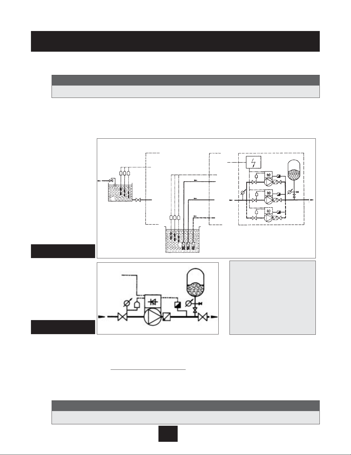
System Design -
Typical Constant Pressure Systems
The following diagrams show typical single pump and multi-pump systems using the AQUAVAR con-
troller. Connection can be made directly to a water supply or water can be drawn from a supply tank or
well. In the case of supply tanks and wells, level switches, (item 10) can be used to shut down the
pumps when water is low. In the direct connection, a pressure switch on the suction side (item 8) can
be used.
A diaphragm pressure tank is used on the discharge side of the pump or pumps to maintain pressure in the line when there is no demand. This will keep the pumps from continuing to run. With the
AQUAVAR controller, it is not necessary to have a large tank for supply purposes. In selecting a tank,
make sure it can withstand maximum system pressure
. The tank should have a capacity of at least
10% of the maximum system flow rate in gpm. Pre-charge the tank to the following:
System Design
1 Pump with AQUAVAR controller
2 Diaphragm tank
3 Distribution panel
4 Gate valves
5 Check valves
6 Foot valves
8 Incoming pressure switch
9 Pressure gauges
10 Level switches
11 Supply tank
14 Pressure transmitter
(Included with AQUAVAR) *
Closed loop circulator systems may not require a pressure tank.
Note
Systems MUST be designed by qualified technicians only.
Note
PSI Set Pressure 15 30 45 60 75 90 105 120 135 150
PSI Tank Pre-charge 12 21 37 52 64 77 95 110 125 138
Diagram 2
Single Pump Layout
Diagram 1
Multiple Pump Layout
Indirect connection
via tank
Suction out or a well
Direct connection
10
11
10
6
9
8
4
3
8
4
8
4
1
1
1
14
5
4
14
5
4
14
5
4
2
9
9
4
8
1
5
4
9
14
2
*Check with tank pressure limitations before precharge.
Page 7

Important: Read all safety information prior to
installation of the AQUAVAR controller.
1. This manual is intended to assist in the installation, operation, and repair of the AQUAVAR controller
and must be kept with the AQUAVAR controller.
2. To avoid serious or fatal personnel injury or major property damage, read and follow all safety
instructions in this manual.
This is a SAFETY ALERT SYMBOL. When you see this symbol on the pump or
in the manual, look for one of the following signal words and be alert to the
potential for personal injury or property damage.
Warns of hazards that WILL cause serious personal injury, death, or
major property damage.
Warns of hazards that CAN cause serious personal injury, death, or
major property damage.
Warns of hazards that CAN cause personal injury or property damage.
Indicates special instructions which are very important and must be
followed.
Note
6
Safety Instructions
NOTICE
All operating instructions must be read, understood, and followed by the operating
personnel. Goulds Pumps accepts no liability for damages or operating disorders
which are the result of non-compliance with the operating instructions.
When in
doubt, call for assistance.
Note
DANGER
WARNING
CAUTION
Page 8

7
Safety Instructions
3. Installation and maintenance MUST be performed by properly trained and qualified personnel.
4. Review all instructions and warnings prior to performing any work on the AQUAVAR controller.
5. Any safety decals MUST be left on the AQUAVAR controller unit and pump.
6. In addition to instructions contained in this manual, you must meet any local safety, electrical, or
plumbing codes and requirements. Installation, maintenance, or repair work must only be
carried out by trained, skilled, and qualified personnel, using proper protective gear and
tools.
7. The AQUAVAR controller drive head must be disconnected from the main power
supply before attempting any operation in the electrical or mechanical part of the
system.
Safety Instructions
When in operation, the motor can be stopped, but power remains at the drive head. The
motor and pump could start unexpectedly and produce serious injury. When the AQUAVAR
controller drive head is connected to the main power supply, the inverter power supply
and master control unit are also connected to the power supply.
Inspect AQUAVAR controller for any damage after unpacking from shipping crates.
Report any damage immediately to the carrier or distributor/dealer immediately.
Note
Note
FAILURE TO DISCONNECT ELECTRICAL POWER BEFORE ATTEMPTING ANY
MAINTENANCE CAN C AUSE SHOCK, BURNS, OR DEATH.
WARNING!
WARNING
Hazardous voltage
can shock, burn or
cause death.
Page 9

8
8. The AQUAVAR controller has electronic safety devices which will stop the motor in the event of
electrical or thermal faults. This does not remove power to the AQUAVAR controller.
9. The system must be properly grounded before being put into operation. Use a common
ground for the entire system.
10. High voltage tests of the AQUAVAR controller may damage the electronic components.
Before carrying out such a test, bridge the incoming and outgoing terminals L1 - L2 - L3 - U - V W. Isolate the motor from the AQUAVAR controller drive to avoid incorrect capacitor metering inside
the AQUAVAR controller.
Safety Instructions
FAILURE TO DISCONNECT AND LOCKOUT ELECTRICAL POWER AND WAIT
FIVE MINUTES FOR C APACITOR DISCHARGE BEFORE SERVICING AQUAVAR
CONTROLLER CAN C AUSE SHOCK, BURNS, OR DEATH.
WARNING!
TOUCHING THESE COMPONENTS SERIOUSLY ENDANGERS LIFE! Voltages of up to
800 volts are possible (higher if there is a fault).
Before removing the AQUAVAR controller drive top cover, the system must be discon-
nected from the main power supply. After switching off the power supply, you must
wait at least 5 minutes before starting work on or inside the AQUAVAR controller drive
head. This allows the capacitors in the circuit to be discharged by the discharge
resistors.
Note
Care must be taken when connecting external control wires and jumpers to avoid short circuit to neighboring components.
Note
Repair of electrical faults can lead to the automatic restart of the motor and pump.
You must remove all main line power to the AQUAVAR controller before attempting to
correct a fault.
Note
WARNING
Hazardous voltage
can shock, burn or
cause death.
Page 10

Step 1- Identif y Materials
The following materials are provided with the AQUAVAR II controller. Please familiarize yourself with each prior to
installation.
Part Quantity
1. AQUAVAR Controller 1
2. Pressure Transducer Assembly 1
a. Pressure transducer - 25 bar
1
/4
” NPT
b. Transducer adapter - (
available as
1
/4
” NPT female threads &
3
/8
B male thread per
separate part only)
See price book.
UNI ISO/228/1 (British Standard pipe threads)
c. 30 ft. transducer cord (standard)
for AV II.
THE AQUAVAR CONTROLLER AND PUMP MUST BE TOTALLY DISCONNECTED FROM ALL
POWER SUPPLY SOURCES BEFORE BEGINNING INSTALLATION OR REPAIR.
WARNING
FAILURE TO DISCONNECT ELECTRICAL POWER BEFORE ATTEMPTING ANY MAINTENANCE CAN C AUSE SHOCK, BURNS, OR DEATH.
WARNING!
WARNING
Hazardous voltage
can shock, burn or
cause death.
3.45
1.07
3
⁄4” HEX
1
⁄4” NPT
2c 2a
2b
(If needed.)
9
Installation Procedures
YOU MUST USE THE CABLE THAT IS PROVIDED WITH THE TRANSDUCER. DO NOT USE
DIFFERENT CABLES OR OLDER STYLE C ABLES.
Note
Page 11

10
Installation Procedures
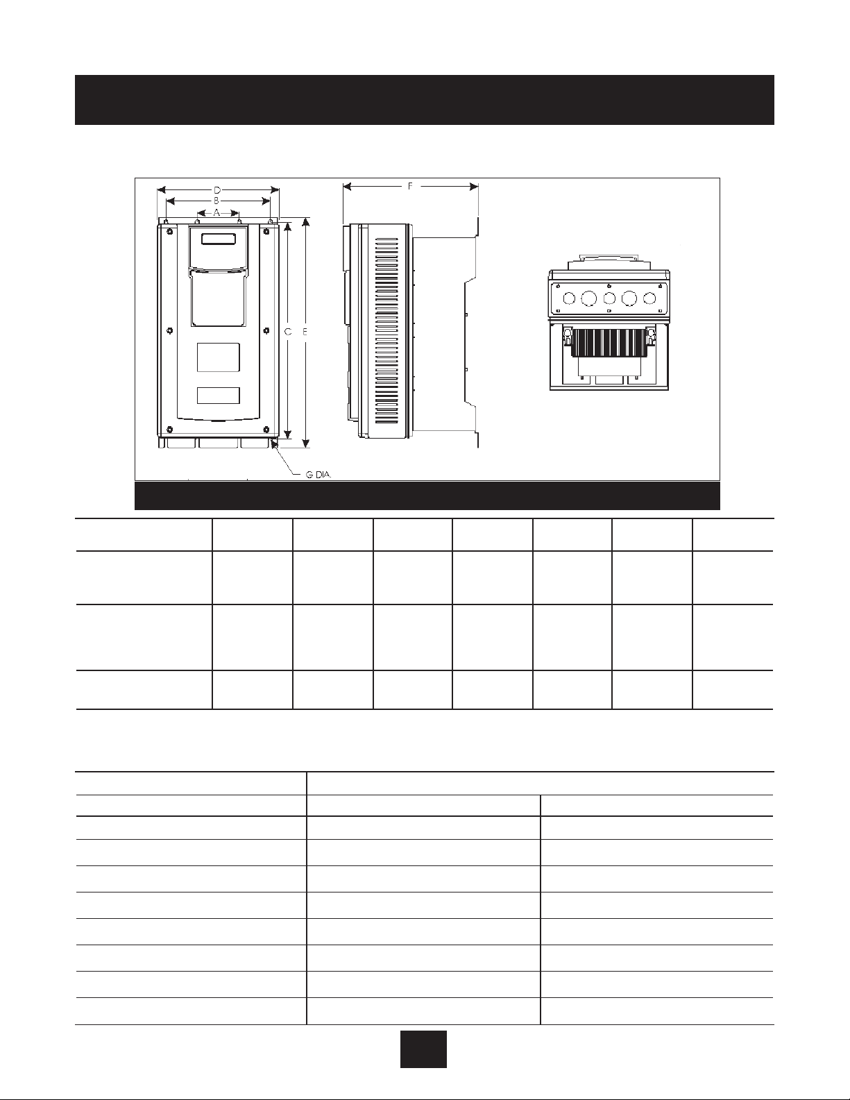
Step 2 - Mounting the AQUAVAR
II
controller:
AQUAVAR Controller
The AQUAVAR controller may be installed as a wall or panel mounted unit. The AQUAVAR controller may
be mounted up to 60 feet away from the pump motor*. In addition, alternative motor enclosures
may be selected such as ODP, explosion proof or wash down motors in addition to the TEFC enclosure required for on the pump mounting.
Typical applications for the AQUAVAR Wall Mount controller include:
1. Hazardous environment applications including high heat, humidity or combustibility.
2. Installation to an existing pumping system with non-standard motors.
3. Installations where the operator desires all controls to be grouped together.
Mounting of the AQUAVARII Controller
1. An alternative mounting style is used in the AQUAVAR
II
controller configuration.
In this style, the AQUAVAR
II
controller is supplied with a fan and mounting bracket already
installed and can be mounted to a wall or panel.
2. The mounting bolts for all units should be 1⁄4". The length of bolt and the strength of the
mounting surface must be adequate to support the weight of the AQUAVAR
II
controller.
3. The AQUAVAR
II
controller may be positioned up to 60 feet from the pump motor. The pump
motor must be three phase. Unlike the standard AQUAVAR controller, the motor may be
ODP, TEFC or explosion proof.*
4. Mount the AQUAVAR controller to the panel, wall or frame using bolts at the points indicated
on the following drawings. Be sure the unit is level and secured to the mounting surface
before continuing.
5. Ensure plenty of airflow for the AQUAVAR controller, when mounting.
*NOTE: If the AQUAVAR
II
controller is more than 60 feet wire length to motor, then the use of a
load reactor (impedance coil) is required.
Page 12
Installation Procedures
Step 2 - Mounting the AQUAVAR controller:
(continued)
Power Rating Weight
HP Pounds Kilograms
1 24.0 10.9
2 24.0 10.9
3 24.0 10.9
5 24.0 10.9
71⁄
2
24.0 10.9
10 24.0 10.9
15 28.0 12.7
20 28.0 12.7
HP Rating
ABCDE FG
in (mm) in (mm) in (mm) in (mm) in (mm) in (mm) in (mm)
1 – 10 (230 – 3)
3.20 7.88 16.50 9.32 17.44 12.08 0.28
1 – 5 (230 – 1)
(81.28) (200.15) (419.10) (236.70) (442.98) (306.71) (7.11)
1 – 20 (575)
15 – 20 (230 – 3)
7
1
⁄2 – 10 (230 – 1) 3.20 7.88 19.25 11.44 20.19 13.51 0.28
25 – 40 (460) (81.28) (200.15) (488.95) (290.53) (512.83) (343.20) (7.11)
25 – 40 (575)
25 – 75 (460) 3.20 7.88 28.00 12.68 31.37 14.00 0.42
25 – 75 (575) (81.28) (200.15) (711.20) (322.07) (796.80) (355.60) (10.67)
Note that the E-dimension in the 50-75 HP is maximum overall height to the conduit box rather than the bottom of the foot.
Diagram 3
WEIGHTS OF MODELS - Table 1: NEMA 12
11
Page 13

12
Electrical Connections
Installation Procedures
FAILURE TO DISCONNECT AND LOCKOUT ELECTRICAL POWER AND WAIT
FIVE MINUTES FOR C APACITOR DISCHARGE BEFORE SERVICING AQUAVAR
CONTROLLER CAN C AUSE SHOCK, BURNS, OR DEATH.
WARNING!
WARNING!
Installation and maintenance must only be performed by properly trained and
qualified personnel equipped with the proper tools.
Note
INSTALL AN ALL LEG DISCONNECT SWITCH NEAR THE MOTOR.
INSTALL, GROUND, AND WIRE ACCORDING TO LOCAL AND
NATIONAL ELECTRICAL CODE REQUIREMENTS.
DISCONNECT AND LOCKOUT ELECTRICAL POWER BEFORE
INSTALLING OR SERVICING.
MOTORS WITH AUTOMATIC THERMAL PROTECTION MAY OPEN THEIR
ELECTRICAL CIRCUIT WHEN A THERMAL OVERLOAD EXISTS. THIS CAN
CAUSE THE MOTOR TO START UNEXPECTEDLY AND WITHOUT WARNING.
ELECTRICAL SUPPLY MUST
MATCH PUMP’S AND AQUAVAR CONTROLLER NAME
PLATE SPECIFICATIONS. INCORRECT VOLTAGE OR WIRING CAN CAUSE FIRE
DAMAGE, AND VOIDS WARRANTY.
WARNING
Hazardous voltage
can shock, burn or
cause death.
WARNING
Hazardous voltage
can shock, burn or
cause death.
Power Rating Weight
HP Pounds Kilograms
25 52.0 23.6
30 52.0 23.6
40 60.0 27.2
50 107.0 48.6
60 107.0 48.6
75 107.0 48.6
Page 14

Electrical Connections continued
Step 3 - Preliminary Inspection
Before storing or installing the AQUAVAR controller, thoroughly inspect the device for possible
shipping damage. Upon receipt:
1. Remove the controller from its package and inspect exterior for shipping damage. If damage is
apparent, notify the shipping agent and your sales representative.
2. Remove the cover and inspect the controller for any apparent damage or foreign objects.
Ensure that all mounting hardware and terminal connection hardware is properly seated,
securely fastened and undamaged.
3. Read the technical data label affixed to the controller and ensure that the correct horsepower
and input voltage for the application had been purchased.
4. If you will store the controller af ter receipt, place it in its original packaging and store in a
clean, dry place free from direct sunlight or corrosive fumes, where the ambient temperature
is not less than -20ºC (-4ºF) or greater than +65ºC (+149ºF).
Step 4 - Installation Precautions
Improper installation of the AQUAVAR controller will greatly reduce its life. Be sure to observe the
following precautions when selection a mounting location. Failure to obser ve these
precautions will void the warranty!
1. Do not install the controller in a place subjected to high temperature, high humidity, excessive
vibration, corrosive gases or liquids or airborne dust or metallic particles. See Technical Data
Appendix B for temperature, humidity and maximum vibration limits or contact factor
y.
2. Do not mount the controller near heat-radiating elements or in direct sunlight.
3. Mount the controller vertically and do not restrict the air flow to the heat sink fins.
4. The controller generates heat. Allow sufficient space around the unit for heat dissipation.
13
Installation Procedures
CAUTION!
EQUIPMENT DAMAGE HAZARD - DO NOT OPERATE OR INSTALL ANY CONTROLLER THAT APPEARS DAMAGED. FAILURE TO OBSERVE THIS INSTRUCTION CAN RESULT IN INJURY OR EQUIPMENT DAMAGE.
Page 15

14
Electrical Connections continued
Step 5 - Considerations for Mounting AQUAVAR Controllers
in Host Enclosures
The AQUAVAR controller is available from stock in a variety of enclosures that meet the requirements
of almost any application. Yet, special applications (such as use in washdown environments or in
integrated systems) may make it desirable to mount AQUAVAR controllers in a host enclosure.
When the AQUAVAR controllers are mounted in a host enclosure, the watts dissipated by the drives
must be dissipated by the host enclosure. If this is not accomplished, the control circuitry of the
AQUAVAR controller will be damaged.
Two techniques are available for mounting AQUAVAR controllers in a host enclosure:
• The controllers may be entirely enclosed in the host enclosure or
• The controllers may be mounted with their cooling fins outside of the host enclosure.
The following sections discuss these two mounting techniques in greater detail.
Models Entirely Enclosed in the Host Enclosure
When an AQUAVAR controller is entirely enclosed in a host enclosure, the host enclosure must be
properly sized to dissipate the heat generated by the controller and any other power-dissipated
by the various models of the AQUAVAR controller at various switching frequencies. Use this
information to adequately size the host enclosure.
Models with Fins External to the Host Enclosure
By mounting an AQUAVAR controller so that its heatsink fins are outside of the host enclosure, you
may select a smaller host enclosure than that required when the controller is mounted entirely
inside the host enclosure. For most applications with this type of mounting, typically you will not
need such additional cooling devices as fans, heat exchangers or air conditioners.
The amount by which the load on the host enclosure is reduced is the amount of watts dissipated
by the heatsinks of the controllers. Table 3 shows the watts dissipated by each AQUAVAR model
after deducting the amount of watts dissipated by the heatsinks of the model. Use the values
shown in the table to adequately size the host enclosure.
Installation Procedures
Page 16

Installation Procedures
15
AQUAVAR
Switching Frequency
Max. Switching
Model
Watts Dissipated Watts Dissipated Watts Dissipated
Frequency for
AV2V-
at 4 kHz at 7 kHz at 10 kHz
Rated Current (kHz)
2S010D 37 44 51 10
2S020D 59 71 81 10
2S030D 77 92 106 10
2S050D 162 212 220 10
2S075D 195 251 271 10
2S100D 267 312 354 10
20010D 37 44 51 10
20020D 59 71 81 10
20030D 77 92 106 10
20050D 112 135 156 10
20075D 162 212 220 10
20100D 195 251 (1) — 6
20150D (2) (2) (2) (2)
20200D (2) (2) (2) (2)
40010D 33 43 53 10
40020D 52 69 84 10
40030D 68 90 110 10
40050D 99 131 161 10
40075D 112 144 174 10
40100D 139 180 217 10
40150D 170 210 255 (1) 9
40200D 200 245 — 7
40250D 280 383 — 7
40300D 335 371 (1) — 5
40400D 398 (1) — — 2.5
40500D 600 670 (1) — 5
40600D 710 (1) — — 4
40750D 720 (1) — — 2
50010D 40 52 64 10
50020D 62 83 101 10
50030D 82 108 132 10
50050D 85 115 155 10
50075D 91 131 172 10
50100D 112 160 — 8
50150D 164 — 282 (1) 9
50200D 218 277 (1) — 6
50250D 286 364 (1) — 6
50300D 343 388 (1) — 5
50400D 417 — — 4
50500D 700 — — 4
50600D 720 (1) — — 3
50750D 745 (1) — — 2
(1) Dissipation at rated current and
maximum switching frequency.
Electrical Connections continued
Table 2: Required Dissipation for Models Entirely Inside an Enclosure
Page 17

Installation Procedures
16
AQUAVAR
Model
Watts Dissipated
AV2V2S010D 19
AV2V2S020D 20
AV2V2S030D 27
AV2V20010D 19
AV2V20020D 20
AV2V20030D 27
AV2V20050D 29
AV2V20070D 36
AV2V20100D 34
AV2V20150D 68
AV2V20200D 73
AV2V40010D 20
AV2V40020D 21
AV2V40030D 27
AV2V40050D 30
AV2V40070D 36
AV2V40100D 40
AV2V40150D 46
AV2V40200D 50
AV2V40250D 75
AV2V40300D 76
AV2V40400D 80
AV2V40500D 134
AV2V40600D 145
AV2V40750D 150
AV2V50010D 20
AV2V50020D 21
AV2V50030D 27
AV2V50050D 30
AV2V50070D 33
AV2V50100D 39
AV2V50150D 43
AV2V50200D 44
AV2V50250D 73
AV2V50300D 78
AV2V50400D 82
AV2V50500D 135
AV2V50600D 143
AV2V50750D 152
Electrical Connections continued
Table 3: Required Dissipation When Fins are External to the Enclosure
Page 18

Installation Procedures
17
Electrical Connections continued
Step 6 - Maintenance
Minimum Torque Values to Secure Cover
If you remove the cover of an IP55 AQUAVAR controller, it is imperative that the cover be
closed and re-secured with sufficient tightness to maintain environmental integrity. The table
below specifies the torque values for the bolts that secure the covers on the various models.
Step 7 - General Wiring Information
Wiring Practices
When making power and control connections, observe these precautions:
• Follow all Federal, State, NEC codes and local codes.
• Never connect input AC power to the motor output terminals T1/U, T2/V or T3/W – or
damage to the controller will result.
• Power wiring to the motor must have the maximum possible separation from all other power
wiring. Do not run in the same conduit, this separation reduces the possibility of coupling
electrical noise between circuits.
• Cross conduits at right angles whenever power and control wiring cross.
• Good wiring practice also requires separation of control circuit wiring from all power wiring.
Since power delivered from the controller contains high frequencies which may cause
interference with other equipment, do not run control wires in the same conduit or raceway
with power or motor wiring.
Considerations for Power Wiring
Power wiring refers to the line and load connections made to terminals L1/R, L2/S, L3/T and
T1/U, T2/V, T3/W respectively. Select power wiring as follows:
• Use only UL recognized wire. (Shielded or armored wire is recommended for power and motor
wiring.)
• Wire voltage rating must be a minimum of 300 V for 230 Vac systems and 600 V (Class 1 wire)
for 460 Vac and 575 Vac systems.
AV2 Enclosure Type
Torque Value
English Metric
1-20 HP, 230 Vac input 12 in-lbs 1.35 Nm
IP55 1-20 HP, 460 and 575 Vac input 18 in-lbs 2.03 Nm
25-75 HP, 460 and 575 Vac input 12 in-lbs 1.35 Nm
Page 19

Electrical Connections continued
• Use circuit breakers on the incoming power lines.
• Grounding must be in accordance with NEC and CEC. If multiple AQUAVAR controllers are
installed near each other, each must be connected to ground. Take care to not form a ground
loop. Maintain a common ground.
• Wire must be made of copper and rated 60 / 75ºC (unless otherwise specified in the table
below). Refer to Tables 4, 5 and 6 for recommended wire gauges and temperature ratings.
Considerations for Control Wiring
Control wiring refers to the wires connected to the control terminal strip. Select control wiring
as follows:
• Shielded wire is recommended to prevent electrical noise interference from causing improper
operation or nuisance tripping.
• Use only UL™ recognized wire.
• Wire voltage rating must be at least 300 V for 230 Vac systems.
Installation Procedures
18
Model
Wire Size 208 Vac Wire Size 230 Vac
Number
AWG mm
2
AWG mm
2
AV2V2S010D 14 2.5 14 2.5
AV2V2S020D 12 4.0 12 4.0
AV2V2S030D 10 6.0 10 6.0
AV2V2S050D 8 10.0 8 10.0
AV2V2S075D 6 16.0 6 16.0
AV2V2S100D 4 25.0 4 25.0
AV2V20010D 14 2.5 14 2.5
AV2V20020D 14 2.5 14 2.5
AV2V20030D 12 4.0 14 2.5
AV2V20050D 10 6.0 10 6.0
AV2V20070D 8 10.0 8 10.0
AV2V20100D 8
1
10.0
1
8 10.0
AV2V20150D 6
1
16.0
1
6
1
16.0
1
AV2V20200D 6
1
16.0
1
6
1
16.0
1
(1) Use wire rated 90ºC in an environment where the ambient temperature is greater than 40ºC (122ºF).
Table 4: Recommended Wire Gauges (230 Vac Models)
Page 20

Model Number
Wire Size
AWG mm
2
AV2V50010D 14 2.5
AV2V50020D 14 2.5
AV2V50030D 14 2.5
AV2V50050D 14 2.5
AV2V50075D 14 2.5
AV2V50100D 12 4.0
AV2V50150D 10 6.0
AV2V50200D 8 10.0
AV2V50250D 8 10.0
AV2V50300D 8 10.0
AV2V50400D 6
1
16.0
1
AV2V50500D 4
1
25.0
1
AV2V50600D 4
1
25.0
1
AV2V50750D 2
1
35.0
1
(1) Use wire rated 90ºC in an environment where the ambient temperature is greater than 40ºC (122ºF).
Installation Procedures
19
Electrical Connections continued
Table 5: Recommended Wire Gauges (460 Vac Models)
Model Number
Wire Size
AWG mm
2
AV2V40010D 14 2.5
AV2V40020D 14 2.5
AV2V40030D 14 2.5
AV2V40050D 14 2.5
AV2V40075D 12 4.0
AV2V40100D 12 4.0
AV2V40150D 10 6.0
AV2V40200D 10
1
6.0
1
AV2V40250D 8
1
10.0
1
AV2V40300D 6
1
16.0
1
AV2V40400D 6
1
16.0
1
AV2V40500D 3
1
35.0
AV2V40600D 2
1
35.0
1
AV2V40750D 1
1
50.0
1
(1) Use wire rated 90ºC in an environment where the ambient temperature is greater than 40ºC (122ºF).
Table 6: Recommended Wire Gauges (575 Vac Models)
Page 21

Installation Procedures
Electrical Connections continued
Step 8 - Input Line Requirements
Line Voltage
See the Power and Current Ratings table for the allowable fluctuation of AC line voltage for your
particular model. A supply voltage above or below the limits given in the table will cause the
drive to trip with either an overvoltage or under voltage fault.
When supplying line voltages other than the factory default values (either 230 Vac, 460 Vac or
575 Vac depending on the model), set the Supply Voltage parameter to the appropriate value.
Exercise caution when applying the AQUAVAR controller on low-line conditions.
For example, and AQUAVAR controller will operate properly on a 208 Vac line – but the maximum
output voltage will be limited to 208 Vac. Now if a motor rated for 230 Vac line voltage is
controlled by this drive, higher motor currents and increased heating will result.
Therefore, ensure that the voltage rating of the motor matches the applied line voltage. If other
than 60 Hz output is desired, proper V/Hz can be programmed into the AVII by setting the
Nom Mtr Voltage and Nom Mtr Freq parameters.
Use of Isolation Transformers and Line Reactors
The AQUAVAR controller is is per fectly suitable in most cases for direct connection to a power source
as specified in this manual and the technical nameplate affixed to the unit. There are however a
few cases where a properly sized isolation transformer or line reactor should be employed to
minimize the risk of drive malfunctionor damage or nuisance tripping:
• As noted in
Table 7
, transformer sizing, when line capacity is greater than 10 times the KVA
rating of the drive. Consult the factory for assistance in sizing the reactor.
• When power factor correction capacitors are employed on the drive’s power source.
• When the power source is known to be subject to transient power interruptions or
significant voltage spikes.
• When the power source supplying the drive also supplies large devices such as DC drives
that contain controller rectifiers.
Table 7: Transformer Sizing for the AQUAVAR Controller
Controller HP 1 2 3 5 7.5 10 15 20 25 30 40 50 60 75
Transformer kVA 2 4 5 9 13 18 23 28 36 42 56 70 90 112
20
Page 22

Electrical Connections continued
Phase Imbalance
Phase voltage imbalance of the input AC source can cause unbalanced currents and excessive
heat in the drive’s input rectifier diodes and DC bus capacitors. Phase imbalance can also damage
motors running directly across the line.
Step 9 - Terminals Found on the Power Board
Description of the Terminals
Diagram 4 shows the power terminals for the AQUAVAR controller. Table 8 describes the terminals.
Table 8: Description of Power Terminals
Terminal Description
TB1 Terminal Group
GND Earth ground.
L1/R These terminals are the line connections for three-phase models. (Single-phase
L2/S models will only have the L1/R terminal, with the other two terminals being
L3/T replaced by a terminal labeled N.)
T1/U
T2/V These terminals are for motor connections.
T3W
Installation Procedures
21
CAUTION!
EQUIPMENT DAMAGE HAZARD - NEVER USE POWER-FACTOR CORRECTION
CAPACITORS ON MOTOR TERMINALS T1/U, T2/V OR T3/W. DOING SO WILL
DAMAGE THE SEMICONDUCTORS. FAILURE TO OBSERVE THIS INSTRUCTION CAN RESULT IN INJURY OR EQUIPMENT DAMAGE.
Diagram 4: AQUAVAR Controller Power Terminals
GND
L1/R
L2/S
L3/TB–B+DB
T1/U
T2/V
T3/W
GND
Page 23

Electrical Connections continued
Typical Power Connections
Diagram 5 shows the terminal connections for line power and motor output. See Step 8 for input
line requirements.
Note that when testing for a ground fault, do not short any motor lead (T1/U, T2/V or T3/W) back
to an input phase (L1/R, L2/S or L3/T).
As shown in Diagram 5, it is necessary to provide fuses and a disconnect switch for the input AC
line in accordance with all applicable electrical codes. The drive is able to withstand a 110% over
load for 60 s. For maximum protection of the drive, use the fuses listed in Tables 9, 10 and 11
found below and on the next page. The recommended supplier is Bussman.
Table 9: Recommended Fuses (230 Vac Models)
Fuse Size 208 Vac Fuse Size 230 Vac
Model Number
JJS/JJN
1
JJS/JJN
1
AV2V2S010D 15 10
AV2V2S020D 20 20
AV2V2S030D 30 30
AV2V2S050D 45 45
AV2V2S075D 60 60
AV2V2S100D 80 80
AV2V20010D 10 6
AV2V20020D 15 10
AV2V20030D 20 15
AV2V20050D 30 25
AV2V20075D 40 35
AV2V20100D 50 40
AV2V20150D 70 60
AV2V20200D 70 60
(1) For sizes up to and including 30 A, KTK fuses may be substituted.
Installation Procedures
22
Diagram 5: Connections for Power Wiring
Disconnect
Switch
Fuses
AC Power
Three-Phase
Motor
AV2V Drive
GND
L1/R
L2/S
L3/T
T1/U
T2/V
T3/W
GND
Page 24

Installation Procedures
23
Electrical Connections continued
Table 10: Recommended Fuses (460 Vac Models)
Fuse Size 380 Vac Fuse Size 460 Vac
Model Number
JJS/JJN
1
JJS/JJN
1
AV2V40010D 6 6
AV2V40020D 6 6
AV2V40030D 10 10
AV2V40050D 15 15
AV2V40075D 20 20
AV2V40100D 20 20
AV2V40150D 40 35
AV2V40200D 50 40
AV2V40250D 60 50
AV2V40300D 70 60
AV2V40400D 80 60
AV2V40500D 90 90
AV2V40600D 110 110
AV2V40750D 150 150
(1) For sizes up to and including 30 A, KTK fuses may be substituted.
Table 11: Recommended Fuses (575 Vac Models)
Fuse Size 575 Vac
Model Number
JJS/JJN
1
AV2V50010D 6
AV2V50020D 6
AV2V50030D 10
AV2V50050D 10
AV2V50075D 15
AV2V50100D 20
AV2V50150D 30
AV2V50200D 35
AV2V50250D 50
AV2V50300D 50
AV2V50400D 70
AV2V50500D 70
AV2V50600D 80
AV2V50750D 100
(1) For sizes up to and including 30 A, KTK fuses may be substituted.
Page 25
Electrical Connections continued
1. The wires routed from the
terminal block U, V, W, and
ground screw, should now be
connected to the motor leads
using the motor nameplate and
Diagram 6 for reference. Always
refer to motor wiring nameplate.
2. Pressure Transducer
Installation and Wiring
It is recommended that the
transducer be mounted in the
discharge piping
. The location should be in a non-turbulent, straight piece of pipe. See layout
on page 5. Locate the adapter for the pressure transducer, if needed.
Installation Procedures
24
Diagram 6
Diagram 7
220 Volt 460 Volt
4
3
RS485
AQUAVAR
WU V
GROUND = PE
2
1
X6
4
3
2
X5
1
6
5
4
3
2
1
X2
14
13
12
11
10
9
8
7
6
5
4
3
2
1
X1
Transducer
connection
123
BROWN – 3
WHITE – 2
X9
- 24 VDC
+ 24 VDC
+ 24 VDC
FAULT RELAY
6 – CONNECTED TO DRIVE
5 – CONNECTED TO DRIVE JUMPER
4 – CONNECTED TO DRIVE JUMPER
3 – CONNECTED TO DRIVE
2 – ANALOG OUT (PRESSURE)
1 – RETURN SIGNAL
789
6
AQUAVAR
WU V
123
789
54
GROUND = PE
4
+ 5VDC
3
GND
2
SIO +
1
X5
X2
SIO -
6
NO
5
CC
4
NC
3
NO
2
CC
1
NC
14
Digital Input
13
Voltage Signal Input (0-10Vor 2-10V)
12
Current Signal Input (4-20 mA)
11
10
9
8
7
6
5
4
3
15 V
2
IN
1
X1
* NOTE: Jumpers are installed from the factory.
Must remove to wire motor thermal, low water
switch or external ON/OFF if used.
RS-485
connected to drive
“Run Signal”
fault signal
Analog signal output (0-10V)
connected to drive
Motor thermo or PTC *
low Water or jumper *
external on or jumper *
U
b (max 100 mA)
(4-20 mA)
actual value signal
shielding
Multipump
456
Page 26

Installation Procedures
25
Electrical Connections continued
3. Place the square gasket over the end of the transducer, plug the cable connector on,
and tighten the screw.
• The transducer is supplied with
1
⁄4
” NPT threads for direct mounting in the discharge piping.
4. Now select one of the remaining ports in the AQUAVAR controller to route the transducer cable.
Route the transducer cable through the strain relief, cut to length and connect to locations X1
#2 and #3 as shown in Diagram 7. (Note: Control board is mounted to the inside front cover
of the drive enclosure.) The brown wire is connected to X1 #3 and the white wire to X1 #2.
Tighten strain relief.
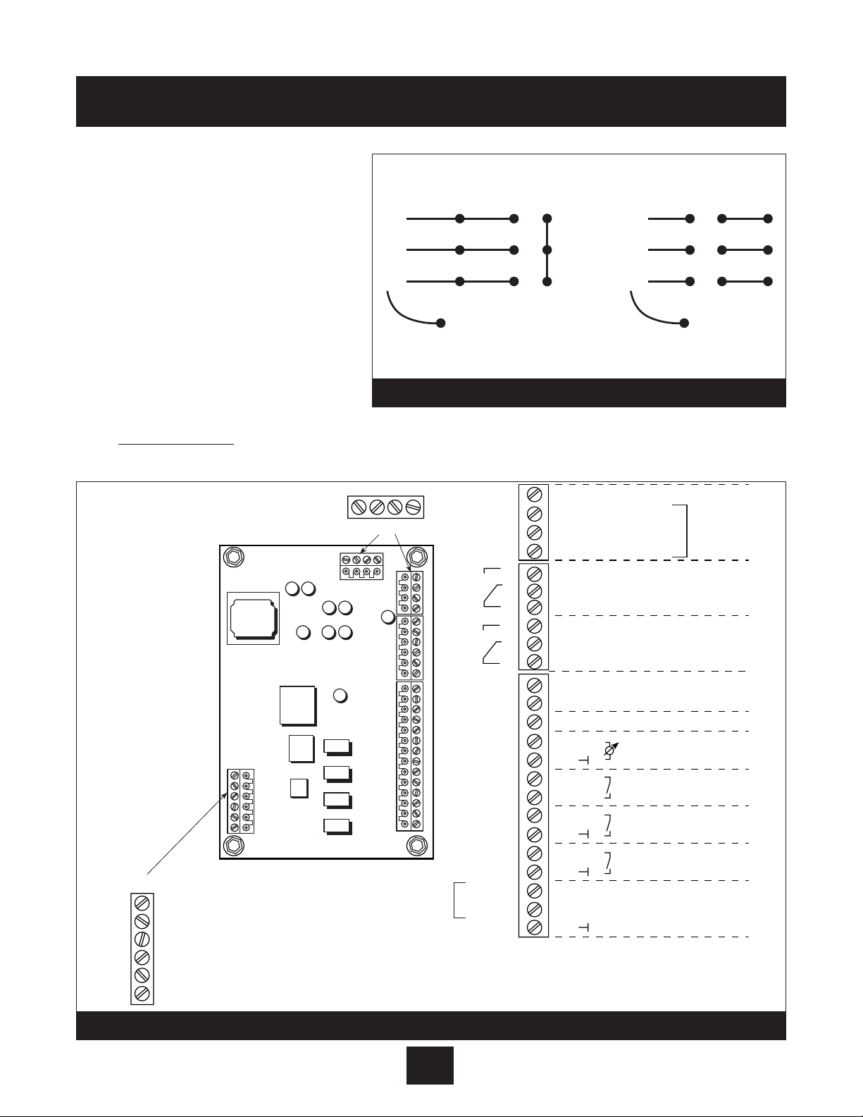
5. Terminals Found on the AV II Drive Control Board (Internal Drive)
Description of the Control Terminals: Figure 8 shows the control terminals found on the I/O
board of the AV IIdrive. (The actual control board cannot be accessed by the user.) These
terminals are prewired by the factory with color coded wires below.
Note that due to labeling constraints, the labels for some terminals start on the left (either on
the side or top of the terminal block), are interrupted by the terminal screw, and then finish on
the right (either on the side or top of the terminal block). For example, terminal A11 is labeled
with A on the left side of the block and 11 to the right of the terminal screw on top of the
block. Similarly, terminal NC2 is labeled with N to the left of the terminal screw on top of the
block and then C2 on the
right side of the block.
As is shown in the figure,
the terminals are divided
into four terminal blocks,
each of which pulls apart
for ease of field wiring:
• TB1 - analog input,
analog output and
digital output terminals.
• TB2 - output relay 1 (R1).
• TB3 - output relay 2 (R2).
• TB4 - digital input
terminals.
Table 12 starting on the
next page describes the
control terminals.
Cable connector will fit on one way only! Do not force on or damage may occur.
Note
Diagram 8
Enhanced
Keypad
Port
On side of
terminal block
Yellow Wire
White Wire
Black Wire
CM
CM
CM
CM
CM
DQ
DQ
DQ
10
9
8
7
6
5
4
3
2
1
24
24
24
C2
C2
O2
On side of
terminal block
Black Wire
Jumper
Blue Wire
Orange Wire
Red Wire
TB1
A0
A0
CM
A1
A1
CM
A
11
12
A
+
10
21
A
CM
CM
CM
D
PQ
3
DIP Switches
2
1
C1
R
N
C1
N
C1
TB2
TB4
CM
EN
D
D
D
D
D
D
D
D
D
D
+
+
+
R
N
N
TB3
CM
EN
Page 27

26
Installation Procedures
Electrical Connections continued
Table 12: Description of AV II Drive Control Terminals (Internal Drive)
Terminal Description
TB2 Terminal Block
Common terminal for the first auxiliary relay. The function of the relay is
RC1 set by parameter R1 Configure. The default setting is for the relay to
activate when a fault is detected (Drv Flted).
NC1 Normally-closed contact for the first auxiliary relay. It will open when the
relay is activated.
NO1 Normally-open contact for the first auxiliar y relay. It will close when the
relay is activated.
TB3 Terminal Block (Drive Run Contacts)
Common terminal for the second auxiliary relay. The function of the relay
RC2
is set by parameter ROUT R2 Config. The default setting is for the relay
to activate when the drive is running.
The contact ratings are 115 VAC at 1 A or 230 VAC at 0.5 A .
NC2
Normally-closed contact for the second auxiliary relay. It will open when
the relay is activated.
NO2
Normally-open contact for the second auxiliary relay. It will close when
the relay is activated.
TB4 Terminal Block
Enable terminal. A jumper is placed between this terminal and the +2
terminal at the factory. You may replace this with a contact if desired. The
EN
circuit from EN to +24 must be closed for the drive to operate.
Note that unlike all other terminals, this terminal cannot be configured
for “pull-down logic.” That is, a high input to this terminal is always
regarded as true – and must be present if the drive is to operate.
Digital inputs. The function of a digital input is configured by the
D3 to D10 parameter with the same name as the digital input in the DI Configure
parameter group.
Digital input. In 3-wire control, this must be a Stop input. In 2-wire
D2 control, it may be configured to another function with parameter
D2 Configure.
D1 Digital input. This must be a Start or Run input.
Page 28

6. For multi-pump systems:Use a three core shielded cable to connect terminals 1, 2, and 3
on X5 between the AQUAVAR controller units. These are the RS-485 inter face connections.
(See Diagram 11 and 13). Note: either RS485 port can be used.
• Connect pump one to pump two, two to three, and three to four (maximum is 4 pumps).
7. External pressure switch or float switch- (if used) to check incoming pressure and low/no
suction. Connect to terminal block X1 at the 6 and 7 location. Refer to Diagram 11.
When using a suction pressure switch, set the cut off at the maximum NPSH required by the pump.
8. External on/off
If used to turn the AQUAVAR controller on or off from an external panel or controller, connect to
terminal block X1 at the 4 and 5 location (refer to Diagram 7, page 24).
9. Analog output of pressure
A meter can be connected to X9 pins 2 and 1 for remote display of actual system pressure.
The meter must be 0-10 VDC volt with no more than 2 mA.
10. Second Sensor Input
The ground pin (X1-10) used for analog output can also be used to bridge a connection for
a second sensor. This can be digital (on/off) such as a switch which would be connected
between X1-10 and X1-14. Another choice is a sensor with a voltage signal of 0-10V or 2-10V
which would be connected to X
1-10 and X1-13. A final choice is a 4-20 mA current sensor
which would be connected to pins X
1-10 and X1-12.
27
Installation Procedures
Power supplies using G.F.I. breakers will cause nuisance tripping which will result in the
AQUAVAR
controller displaying an “undervoltage” fault.
Note
If an external switch is NOT used, install a jumper wire between X1 Locations 4 and 5.
Note
Diagram 9
4
3
2
X5
1
6
5
4
3
2
1
X2
14
13
12
11
10
9
8
7
6
5
4
3
2
1
X1
4
3
2
X5
1
6
5
4
3
2
1
X2
14
13
12
11
10
9
8
7
6
5
4
3
2
1
X1
4
3
2
X5
1
6
5
4
3
2
1
X2
14
13
12
11
10
9
8
7
6
5
4
3
2
1
X1
Page 29

Pump Priming
Refer to your pump operation manual for instructions on pump priming. You will need to unscrew
the pressure transducer and adapter if you used the pump fill plug for mounting. When priming is
complete, replace the pressure transducer and check for leaks!
Run Test
Instructions
1. Check all wiring.
All motors used with the AQUAVAR controller are
three phase. You will need to check the
direction of rotation of the motor shaft. If you
have followed all of the previous steps carefully,
you should now be ready to apply power to the
AQUAVAR controller unit.
2. Close discharge valve.
Make sure the discharge valve is closed.
Apply power to the AQUAVAR controller. The first
screen appears for 2 seconds and shows the
software version and manufacture date. The
next screen will appear automatically
*If auto start is preprogrammed “ON”, pump will start immediately.
3. Check Power Light
Check the AQUAVAR controller panel. The
“power on”
light should be illuminated and the
display should say
“No Autostart - disable inverter.”
If either of these conditions is not
present, turn off all power to the AQUAVAR controller and recheck all connections.
To change the display language on the AQUAVAR controller, press the “ ” key and the up arrow key at the
same time. A scrolling line will appear on the bottom of the screen and tell you which button to push for
the language you want. After selecting the language, press the up arrow to return to the main display.
Note
FAILURE TO DISCONNECT AND LOCKOUT ELECTRICAL POWER AND WAIT
FIVE MINUTES FOR C APACITOR DISCHARGE BEFORE SERVICING AQUAVAR
CONTROLLER CAN C AUSE SHOCK, BURNS, OR DEATH.
WARNING!
WARNING
Hazardous voltage
can shock, burn or
cause death.
Installation Procedures
DO NOT APPLY POWER TO THE AQUAVAR CONTROLLER OR PUMP UNTIL ELECTRICAL CONNECTIONS HAVE BEEN REVIEWED BY A QUALIFIED ELECTRICIAN AND
MEET ALL APPLICABLE STATE AND LOCAL REQUIREMENTS.
WARNING
Screen
—
NO AUTOSTART - DISABLE INVERTER
ITT Industries
SW:120 Date: 10/30/00
28
*
Page 30

4. Check Display.
* If these conditions exist, proceed.
If NOT, check all wiring.
5. Drive Component Keypad (Internal Drive)
The AQUAVAR
II
units have an additional keypad inside the cabinet. You will need to use
this keypad one time for initial system set up. Once set, all other functions are programmed
with the main display on the front panel. Below are the instructions for initial programming of
the internal keypad.
This keypad provides access to a
comprehensive set of parameters that
allow the AV
II
drive to meet the needs
of almost any application. To make
customization as simple as possible, two
levels of programming are available.
Programming Mode
A. Programming mode is entered by
pressing the PROG key.
B. To program a parameter ’s value, per
form the following steps:
C. Press PROG to initiate programming.
D. The Operate display will change to the list of parameters. An arrowhead indicates which
one is selected.
E. If the desired parameter is indicated by the arrowhead, press ENTER to select the
parameter and display its current value. If the indicated parameter is not the one you
want to program, use the up or down arrow keys to move the arrowhead to the desired
parameter and then press ENTER to select the parameter and display its current value.
F. After the ENTER key is pressed, the value for the parameter will be displayed. For exam-
ple, parameter Motor voltage may range from 100V to 690 V and you may configure
any value
within
that range
as shown
on the
motor
nameplate.
Installation Procedures
29
Screen
NO AUTOSTART - DISABLED INV.
Diagram 11
Diagram 10
2 Line by 16 Character Display
RUN WARNING FAULT PROG POWER
FWD
REV
SHIFT ENTER
PROG
STOP
Sample display for
parameters assigned a value
MIN FREQUENCY
V0301 160.05 Hz
Name of Parameter
Sample display for
parameters assigned a function
STOP TYPE
P0403 CST to Stp
Data
Memory
Address
Value
Units
Can Parameter
Be Changed?
P
Unlocked — Yes.
V
Locked — No.
Memory
Address
10-Character
Description
of Assigned Function
Page 31

G. Use the up or down arrow keys to change the parameter’s value to the desired value.
H. Press ENTER to save the new value. (If you do not wish to save the new value, press
SHIFT.)
I. The new value is stored, or discarded, and then the list of parameters is shown.
J. You may now select another parameter or return to the Operate mode by pressing
the PROG key.
6. You need to set up the AQUAVAR controller for the type of pump motor you are using. Press the
PROG key to display the list of functions. Use the up or down arrow to scroll to the NOM MTR
CURRENT parameter.
7. Press the ENTER key and then the up and down arrows to change the value to match the SFA
(Service Factor Amps) shown on your pump motor data plate. Once complete, press ENTER
again. (Maximum S.F. amps is 10% above nominal controller output amps.)
See pages 86 and 87.
8. Scroll to the NOM MTR VOLTAGE parameter and press ENTER. Use the up and down arrows
to enter the voltage on the motor nameplate. For multi-voltage motors, select the voltage to
match your line voltage. Press ENTER to save the value.
9. Scroll to the NOM MTR FREQ parameter and press ENTER. Use the up and down arrows to
enter the maximum frequency for the motor design you are using. This would be either 50 Hz
or 60 Hz. Press ENTER to save the value.
10. Scroll to the NOM MTR RPM parameter and press ENTER. Use the up and down arrows to
enter the maximum RPM for the motor you are using. THis can be found on the motor
nameplates. Press ENTER to save the value.
11. Scroll to the SUPPLY VOLTAGE parameter. Press ENTER and use the up and down arrows to
put in the voltage available on the input line. Press ENTER to save the value.
12. Scroll to the Language parameter. Press the ENTER key and use the up and down arrows to
change the display language if needed. Press ENTER to save the value.
13. Press the PROG key again, close the panel door and go back to the main AQUAVAR display.
14. Press the down arrow key
The next display will be:
15. Press the up arrow
to turn on the AQUAVAR
II
controller.
16. Open the discharge valve slowly until the pump starts.
Observe the rotation of the pump shaft or motor fan.
17. Close the discharge valve.
18. Press the down arrow to turn off the AQUAVAR
II
controller.
Installation Procedures
(continued)
30
INVERTER STOP - ON -> START
RUN LIGHT ON
▼
▼
▼
Page 32

Installation Procedures continued
19. If the direction of rotation was correct, proceed to the Programming section beginning on
the following page.
20. If the direction was not correct, remove all power from the AQUAVARIIcontroller and wait
five minutes.
Open the motor conduit box and exchange any two of the three motor leads. Close the conduit box.
Repeat steps 15 through 18 to check the direction of the motor shaft rotation.
Programming
Programming of the AQUAVARIIcontroller is accomplished by using the three pressure sensitive buttons on the control panel along with the two line
LCD display.
The format of the program is a series of menus
which can be scrolled through by using the select
button. Each screen display is used to provide
information about the operation of the system or to
change one or more of the operating parameters.
Changes are made by pushing the up or down
arrows.
I. The Main Menu - Setting Single Pump Constant Pressure
Diagram 15 shows the display screens in a flow chart format. Refer to this flow chart for the next 6 steps.
There are ten display screens in the main menu which will allow you to set the required system pressure,
save it, and turn the system on. Several of these display screens were already used during the test run.
After power has been turned on, the
“Power on”
light should be illuminated and the display should
briefly show the software version and date, then show
“No Autostart - disable inverter.”
31
Programming
Diagram 12
▼
▼
Page 33

Instructions
1. Check Power Light
2.
Press the down arrow to advance the display to:
3. Press Select to advance the display to:
4. Enter the pressure you want the pump
to maintain (constant pressure) for your system.
Press the until the reading shows the
value you want. Use the down arrow to back up
if you have gone too far.
For example: if you need a constant pressure
of 50 PSI in your system at various demand
rates, you would enter 50 as the value by
using the .
5. Autostart setting
Press to advance the display to:
(This displays the autostart setting.)
Push to turn the autostart function on.
If the autostart function is on, the AQUAVARIIcontroller will automatically turn on and
resume activity when power is restored after a failure. If autostart is off, the AQUAVAR
II
controller must be manually turned on by the operator after a power failure. Be sure the dis
charge valve is closed to prevent pump start.
32
Programming
REQ. PRESS - XXX PSI
*
▼
▼
▼
50
AUTO START - OFF
AUTO START - ON
Screen
▼
▼
▼
REQUIRED VALUE - XXX PSI
NO AUTOSTART - DISABLE INVERTER
Screen
▼
*
If “Inverter Locked” is displayed, the external on/off switch is in the off position or contacts at X1:4 and 5 are not jumpered.
Note
INVERTER STOP - ON->START
REQUIRED VALVE - XXX PSI
Page 34

6. Press to advance the display to:
This display shows the last recorded error or
fault encountered by the AQUAVAR controller.
7. Press to advance the display to:
This in the error which occurred before the last
one.
8. Press to advance the display to:
The error before error 2.
9. Press to advance the display to:
The error before error 3.
10. Press to advance the display to:
The error before error 4.
11. Press to advance the display to:
This is the total amount of run time of the
motor. It can be reset using a method
described later.
12. Saving changes
Press to advance the display to:
13. Press and hold down BOTH
arrows
at the same time until the display changes to:
This will allow you to save the changes you
have made in the microprocessor memory.
14. Af ter about five seconds the display will
automatically return to:
Push . The AQUAVAR
II
controller will begin to automatically maintain system pressure at the
point you have selected and the display will show the pressure set point.
Programming
33
▼
▼
*
▼
SAVE ??? +
SAVE ??? SAVED
INVERTER STOP - ON->START
If the
AQUAVAR
II controller is not maintaining the rating you selected, check the sen-
sor adjustment procedures on page 60 or check rotation again.
Note
▼
▼
ERROR 5
*
*
TOTAL RUN TIME
0000:00
If you have advanced past a window and want to return to it, press and at
the same time to back up.
Note
*
ERROR 1
ERROR 2
*
*
ERROR 3
*
ERROR 4
▼
*
Page 35

AQUAVAR
II
Controller Program Flow Chart
Single Pump Constant Pressure
II. Single Pump - Pump Protection
The
AQUAVARIIcontroller has the ability to protect the pump by shutting it off in low/no suction or run out conditions.
To set run out protection:
For steps 1 through 8, refer to the flow chart on page 36.
Instructions
1. Password
The password protection prevents
untrained personnel from accidentally
changing the base settings.
• From the main menu, hold down the
key for 2-3 seconds until the display
changes to:
34
Programming
Diagram 13
FAILURE TO SAVE SETTINGS AFTER PROGRAMMING RESULTS IN LOSS OF
PROGRAM VALUES WHEN POWER IS REMOVED!
WARNING
Low/no suction protection can be managed by the installation of a suction line pressure switch,
or float switch for a tank. This switch is connected to the AQUAVARII controller as described
earlier in the Electrical Installation section. The cut off setting for this switch should be the
maximum NPSH required by the pump.
Note
PASSWORD 0000
Screen
*
SW Ver.
Date:
Press • long
ITT Ind.
50 PSI
REQUIRED
VALUE
50 PSI
Auto-START
ON
ERROR 1 ERROR 2 ERROR 3 ERROR 4 ERROR 5
TOTAL RUN
TIME
0000: 41
SAVE ??
– + v
Page 36

2. Press the key until you reach the number
66. You will now be able to access all of the
alternate menus for all AQUAVAR controller
optional controls.
3. Press to advance the display to the next
window:
The jog mode is very useful because it allows
you to check on the actual outgoing frequency
and system pressure. By pressing either or
the controller changes to manual, and you
can change the frequency to set any constant
speed. The Aquavar returns to normal automatic operation when you leave the jog mode
window.
4. Continue to briefly touch the key to
scroll past all of the windows and submenus
until you reach:
5. Hold the key down for 2-3 seconds
until the display changes to:
6. Set the minimum pressure the system is
allowed to maintain before shutting down. For
example, if the set point for the system is 50
PSI, and the operator will allow anything
above 41 PSI, then the conveyor limit would
be set at 40 PSI.
This function can also be turned
off by pressing until “disabled” is shown.
To set timed protection:
7. Delay Time
Enter the amount of
time that the pump is allowed to run at
maximum frequency after pressure begins
to drop below the conveyor limit. This should never occur if the system has been
properly sized and there are no leaks in the system. Note: This delay time is also
applied to low suction pressure switch, on terminal X1, 6 and 7.
35
Programming
SET CONVEYOR LIMIT
40 PSI
DELAY TIME
*
*
SUBMENU ERRORS
CONVEYOR LIMIT
Disabled
▼
▼
*
0066
JOG MODE
▼
▼
Page 37

Press the to enter the number of seconds.
The pump will run after pressure begins to drop
at pump run out or a suction switch activates.
8.
Error Reset Turning this control on will enable the AQUAVARII controller to retry its operation five
times when a fault condition occurs. Turning the control to “off” means that the AQUAVARII
controller will shut down the first time a fault occurs. Select the mode you want by pushing the up
or down arrow key.
• Press to advance the display to:
Press to set the time between attempted
restarts or to disable this function
9. Clear error. The error memor y can be deleted
by entering a password supplied by your
distributor.
Returning to normal operation:
10. Hold down the key for 2-3 seconds
until the display changes to:
11. Briefly touch the key to scroll until you
reach the display:
12. Press both at the same time until the display
changes to:
After a moment, the screen will automatically
return to the main menu start position.
36
Programming
SUBMENU ERRORS
Screen
*
*
▼
▼
SAVE ??? +
SAVE ??? SAVED
▼
▼
*
ERROR RESET
▼
▼
CLEAR ERRORS
0000
▼
“Fatal” errors will always shut down the system the first time.
Note
15 SEC
▼
Page 38

37
Programming - Single Pump Protection
Diagram 14
REQUIRED
VALUE
126.9 PSI
Auto-START
ON
ERROR 1 ERROR 2 ERROR 3 ERROR 4 ERROR 5
TOTAL RUN
TIME
0000: 41
SAVE ??
+
PASSWORD
0000
JOG-MODE
XX Hz
XX PSI
WINDOW
5%
RAMP
HYSTERISIS
80%
RAMP 1
4.0 Sec.
RAMP 2
4.0 Sec.
RAMP 3
70 Sec.
RAMP 4
70 Sec.
MAX.
FREQUENCY
60.0 Hz
MIN.
FREQUENCY
0.0 Hz
CONFIG.
FMIN
F -> 0
STOP–
DELAY FMIN
0 Sec.
SENSOR–
ADJUST
out of range
SENSOR–
CURVE
Linear
NORMALIZE
20 mA –
362.6 PSI
REGULATION
MODE
Normal
START
VALUE
DISABLED
CONFIG. REG.
Val. 2
OFF
RELAY
CONFIG.
Run
Motor
MODE
Controller
SUBMENU
Seq. Control
SUBMENU
RS485–
Interface
FREQU. –
LIFTING
37.0 Hz
LIFT
INTENSITY
0.0%
DIMENSION
UNIT
PSI
SUBMENU
TEST RUN
xxx
SUBMENU
ERRORS
ANALOGUE –
OUT
Actual Value
SUBMENU
Offset
TEST RUN
after 100 h.
OPERATING
HOURS 0000 h.
Control unit’s
operating time
DISP.–
CONTRAST
50%
SET
PASSWORD
xxxx
LOCK
FUNCTION
OFF
SUBMENU
DEFAULT
VALUES
SAVE ??
– + v
PUMP
ADDRESS
OFF
ADC
REFERENCE
Local
CONVEYOR–
LIMIT
disabled
DELAY
TIME
2 sec.
ERROR–
RESET
disabled
CLEAR
ERROR
0000
DEFAULT
EUROPE
– + v
DEFAULT
USA
– + v
TEST RUN
Man.
– + v
TEST –
FREQUENCY
30.0 Hz
ACTU. VALUE
INC.
5.0 PSI
ACTU. VALUE
DEC.
2.1 PSI
ENABLE
SEQ. CTL.
58.0 Hz
SWITCH
INTERVAL
12 hours
SUBMENU
Synch.
Control
BUSARBIT –
DIAG.
0
SOURCE
REQ. VALUE
ADR1
PUMP
SEQUENCE
Adrl disabled
LEVEL 1
2.0%
LEVEL 2
0.0%
INTENSITY 1
0.0%
INTENSITY 2
0.0%
SYNCHRON.
LIMIT
0.0 Hz
SYNCHRON–
WINDOW
2.5 Hz
OFFSET –
INPUT
OFF
SW Ver.
Date:
ITT Ind.
50 PSI
Press • long
Page 39

III. Single Pump - System Cur ve Compensation
The AQUAVAR controller can automatically compensate for system friction losses due to
increased flow. Tables are available in most
pump catalogs indicating the amount of friction loss that can be expected in various sizes
of pipe at different flow rates. Use these
tables to determine the friction loss for the
pipe size you are using at your maximum
flow rate.
Diagram 15 shows a typical system curve.
The system pressure set point is shown at
shut off and the pressure increase is shown
for increasing flow.
Calculate the pressure increase required to
overcome friction loss at maximum flow as
a percent of the set point.
For example, if your required system pressure is 30 PSI, and it takes an additional 3
PSI for friction loss at maximum flow, the
percent increase is 10%.
38
Programming
Diagram 15
H
f = 100%
% f
% f
WINDOW
LIFT INTENSITY
10% OF
SET PRESSURE VALUE
SET PRESSURE
% f
0
0
4
3
2
1
0
Q
Page 40

Entering compensation values:
For steps 1 through 4, refer to the flow chart.
Instructions
1. From the main menu, hold down the key
for 2-3 seconds until the display changes to:
• Enter 66 by pressing the
2. Freq.- Lifting 30.0 hz
This indicates the speed (flow rate)
at which you want the pressure compensation to begin. On a
60 hz system, there is virtually no flow below 40 hz. Set this
frequency with the up arrow. On a 50 hz system, the normal
starting point would be 30 hz.
• Use the key to scroll through the
menu screens until you reach:
Change if required.
3. Use the key to move to the next screen:
• Use the to enter the percentage
pressure increase calculated on page 37.
Increase values are recommended from 0
to 20%. If your friction loss increase is above
20% of your set pressure, please contact the
AQUAVAR distributor or factory for application assistance. 0-99.9% actual.
4. Save the new settings.
• Use the key to scroll to the screen
• Press both the arrows until the display
indicates the save process is complete.
The screen will automatically return to the main menu.
39
Programming
PASSWORD 0000
0066
Screen
FREQ - LIFTING 40.0 HZ
LIFT - INTENS. 0.0%
LIFT - INTENS. 3.0%
SAVE ??? +
SAVE ??? SAVED
▼
*
*
*
*
▼
▼
▼
▼
▼
▼
Page 41

40
Programming - System Cur ve Compensation
Diagram 16
REQUIRED
VALUE
126.9 PSI
Auto-START
ON
ERROR 1 ERROR 2 ERROR 3 ERROR 4 ERROR 5
TOTAL RUN
TIME
0000: 41
SAVE ??
– + v
PASSWORD
0000
JOG-MODE
XX Hz
XX PSI
WINDOW
5%
RAMP
HYSTERISIS
80%
RAMP 1
4.0 Sec.
RAMP 2
4.0 Sec.
RAMP 3
70 Sec.
RAMP 4
70 Sec.
MAX.
FREQUENCY
60.0 Hz
MIN.
FREQUENCY
0.0 Hz
CONFIG.
FMIN
F -> 0
STOP–
DELAY FMIN
0 Sec.
SENSOR–
ADJUST
out of range
SENSOR–
CURVE
Linear
SENSOR
RANGE
20 mA –
362.6 Bar
REGULATION
MODE
Normal
START
VALUE
Disabled
CONFIG. REG.
Val. 2
OFF
RELAY
CONFIG.
Run
Motor
MODE
Multi-
Controller
SUBMENU
Seq. Control
SUBMENU
RS485–
Interface
FREQU. –
LIFTING
37.0 Hz
LIFT
INTENSITY
0.0%
DIMENSION
UNIT
PSI
SUBMENU
TEST RUN
xxx
SUBMENU
ERRORS
ANALOGUE –
OUT
Actual Value
SUBMENU
Offset
TEST RUN
after 100 h.
OPERATING
HOURS 0000 h.
Control unit’s
operating time
DISP.–
CONTRAST
50%
SET
PASSWORD
xxxx
LOCK
FUNCTION
OFF
SUBMENU
DEFAULT
VALUES
SAVE ??
– + v
PUMP
ADDRESS
OFF
ADC
REFERENCE
Local
CONVEYOR–
LIMIT
disabled
DELAY
TIME
2 sec.
ERROR–
RESET
disabled
CLEAR
ERROR
0000
DEFAULT
EUROPE
– + v
DEFAULT
USA
– + v
TEST RUN
Man.
– + v
TEST –
FREQUENCY
30.0 Hz
BOOST
TEST-RUN
10.0%
ACTU. VALUE
INC.
5.0 PSI
ACTU. VALUE
DEC.
2.1 PSI
ENABLE
SEQ. CTL.
58.0 Hz
SWITCH
INTERVAL
12 hours
SUBMENU
Synch.
Control
BUSARBIT –
DIAG.
0
SOURCE
REQ. VALUE
ADR1
PUMP
SEQUENCE
Adrl disabled
LEVEL 1
2.0%
LEVEL 2
0.0%
INTENSITY 1
0.0%
INTENSITY 2
0.0%
SYNCHRON.
LIMIT
0.0 Hz
SYNCHRON–
WINDOW
2.5 Hz
OFFSET –
INPUT
OFF
SW Ver.
Date:
ITT Ind.
50 PSI
Press • long
Page 42

Circulator applications
On circulator pumps, the system curve can be automatically tracked through the use of a differential
pressure transducer. This pressure transducer reads the outgoing discharge pressure and the incoming return pressure and compensates for differences in pressure as demand and speed increase.
Programming is the same as just covered for the single transducer version. Data on the differential
pressure transducer can be found in Appendix A.
IV. Single Pump Constant Flow
A single pump AQUAVAR controller system can also be set to maintain a constant flow by changing
motor speed to create more or less pressure when demand changes. The pump should be selected
so that the flow rate required is approximately in the middle of the pump curve and the maximum
pressure is within the performance of the pump at maximum speed. In general, pumps are not
designed to be piped in series (discharge to suction) due to maximum working pressure limitations.
Select a single pump which meets system requirements through either higher staging or larger
impeller diameters.
An orifice plate with differential transducer or a flow transducer can be used for constant flow applications. Follow the instructions provided with the orifice/transducer or flow transducer assembly for installation procedures and electrical connections.
Instructions
In flow applications, you will want to change the
sensor curve from linear or to quadratic and the
units from PSI to %, when using to orifice/transducer
assembly. To do this, hold down the
key at the main menu until screen:
1. Enter the number 66.
2. Briefly press the key to scroll through
the displays until screen:
3. Use the to change to Quadratic. Note: If
you are using a flow sensor rather than an
orifice plate, leave the sensor curve at linear.
4. Briefly press the key to scroll through
the displays until screen:
41
Programming
PASSWORD 0000
0066
Screen
SENSOR CURVE
QUADRATIC
*
*
*
▼
DIMENSION UNIT PSI
Page 43
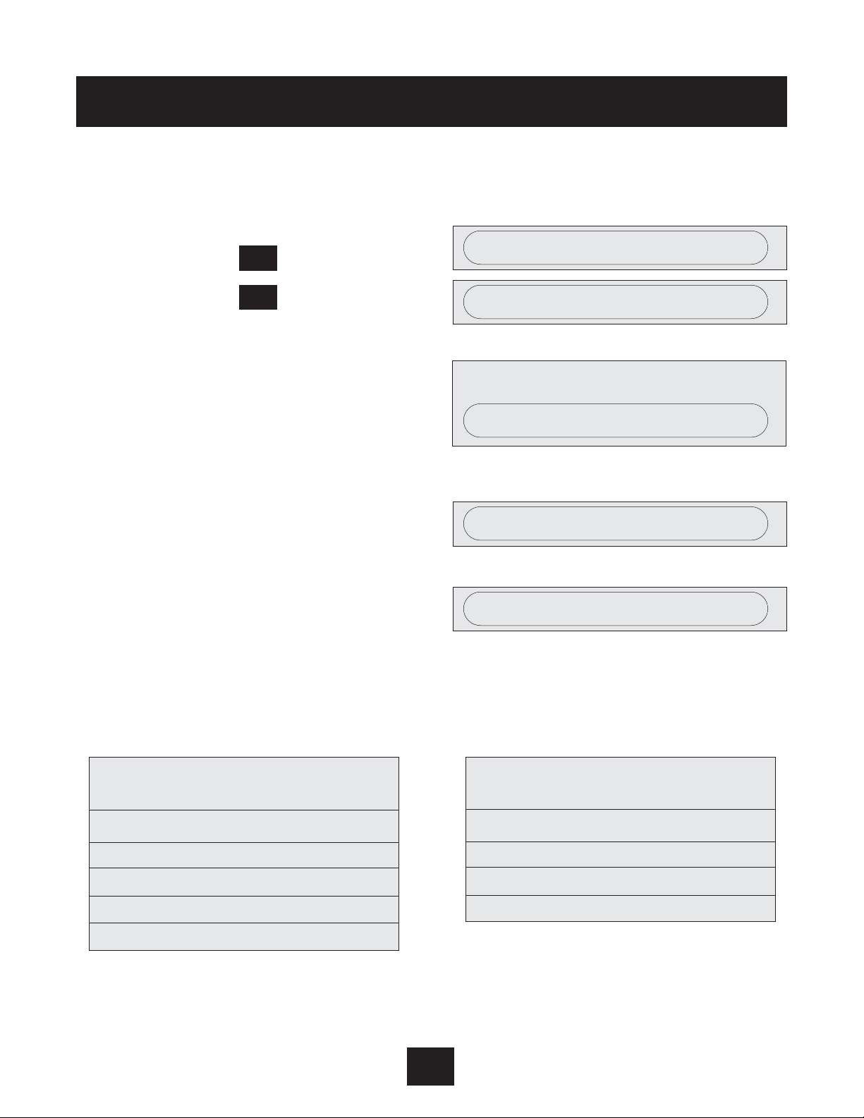
Single Pump Constant Flow continued
5. Use the to change the units to GPM if you are using a flow sensor or % if you are using
the orifice plate.
6. Hold down the key until the screen:
7. Hold down the key until the screen:
8. Enter either 37 psi for orifice plate application or the maximum flow range of your flow
sensor in gpm.
9. Hold down the at the same time until
The display will automatically return to the
main menu.
10. Advance to the screen:
11. Use either to enter the flow you want
to maintain on the AQUAVAR
II
controller
(see example). For orifice plate applications,
use the table below to set the required %.
Select orifice size from the following chart. Select the orifice by the maximum flow of the
pump.
Based on the maximum flow shown for the orifice selected, calculate the percent of maximum flow
you want to maintain. For example, to maintain a flow of 20 GPM with a #1 orifice, select 57% (20
÷ 35).
42
Programming
Screen
REQUIRED VALUE
REQUIRED VALUE 35 GPM
SAVE ??? SAVED
▼
▼
▼
▼
Nominal Pipe Flow Range
Orifice Size GPM
11" 12-35
21" 18-52
31
1
/2" 20-62
41
1
/
2" 32-90
5
2 1/2" 35-105
*
GPM
▼
*
NORMALIZE 20 mA = 40 GPM
Nominal Pipe Flow Range
Orifice Size GPM
6
2 1/2" 52-160
7352-160
8370-210
93120-350
Page 44

V. Single Pump - Level Control Applications
For drainage applications using a surface pump, the transducer is typically needed to measure pressure on the suction line. As the catch basin or tank empties, the pressure will decrease, and the
pump needs to slow down and eventually stop. This is the opposite way the AQUAVAR
II
controller
would usually respond. To change to suction side measurement:
1. On the main menu, enter the PSI value of the
liquid at the LOWEST level you want to maintain. For example, you may want to leave 3-4
feet of water in a tank which is equal to 2-3
PSI.
2. From the main menu, hold down the
key for 2-3 seconds until the screen changes
to:
• Enter 66 by pressing the key.
3. Use the key to scroll to:
• Use the key to change to inverse.
4. Briefly press the key until the screen:
5. Hold down the at the same time until:
The display will automatically return to the
main menu.
In operation, the pump will start wherever the suction side pressure is above the set point and slow
down and stop when the suction pressure comes
down to the set point and stays there.
43
Programming
For discharge level control, the programming operation is the same as a constant discharge pressure system.
Note
REQUIRED VALUE - PSI
Screen
*
*
*
▼
▼
PASSWORD 2000
0066
▼
▼
REGULATION MODE - NORMAL
REGULATION MODE - INVERSE
SAVE ??? SAVED
SAVE ??? +
▼
▼
Page 45

44
VI. Single Pump - Submersible Applications and
Minimum Frequency
It is possible to use the wall mounted version of the AQUAVARIIcontroller with a submersible pump.
*Never attempt to mount an AQUAVAR
II
controller on the pump itself in these applications since the
AQUAVARIIcontroller is not designed to be submerged. The standard distance allowed between the
pump and the AQUAVAR
II
controller is up to 60 feet. If you need a longer connection, be sure to con-
tact your distributor for a drive applied filter or load reactor.
The submersible pump will often use motor service factor and will overload the AQUAVAR
II
controller
at maximum speed. To avoid this, select an AQUAVARIIcontroller based on the service factor amp rating of the motor and the maximum amps allowed by the AQUAVAR
II
. If you have questions about the
requirements of the submersible pump and which AQUAVARIIcontroller to use, please contact the
AQUAVAR
II
controller distributor or factory applications Goulds Pumps.
The submersible pump can be set for either constant pressure or level control applications as
described in programming section I and section V. Normally, the constant pressure application would
use well pumps or turbines with a steady source of water. Drainage applications would normally use
a sump, effluent or sewage pump.
Minimum F
requency
Many submersible well pumps have a required minimum frequency to keep motor bearings lubricated. To avoid running the motor at lower frequencies, you can program in a minimum frequency. For
most Franklin submersible motors the minimum is 30 Hz, so a setting of 35 Hz is good.
Programming
End suction centrifugal pumps may also be used in level control systems for draining
or filling. Multiple pumps end suction or submersible systems may also be used in
level control.
NOTE
Page 46

Programming
45
At the status window, hold the key until you
reach the password screen. Enter the password.
Use the key to advance to:
Use the and to change to the desired minimum
frequency (Example 35 Hz).
Use the key to advance to:
Use the and arrow keys to change to:
This allows the AQUAVAR
II
to go down to the select-
ed minimum frequency but not below it.
Use the key to advance to:
Use the and keys to enter the number of seconds the AQUAVAR
II
will run at minimum speed
before it shuts off when there is no demand.
Advance to the same window and save all settings.
PASSWORD 0066
*
MINIMUM FREQUENCY
0 Hz
MINIMUM FREQUENCY
35 Hz
*
▼
▼
*
CONFIG. FMIN
F -> FMIN
CONFIG. FMIN
F => 0
▼
▼
In the setting f -> Fmin, the
AQUAVAR
II will only run between minimum frequency
and maximum frequency. Automatic shut off is not possible, but manual shut off is
possible with external on/off connected at X1/4 and X1/5.
Note
STOP - DELAY FMIN
OS
*
STOP - DELAY FMIN
10
▼
▼
SAVE ??? +
▼
▼
Page 47

VII. Setting A Second Fixed Required Value
The AQUAVARIIcontroller can also be used in applications where the required value changes. As an
example, a single pump system might be used to supply both water supply and irrigation needs on
a farm. When the irrigation system is used, the pressure which needs to be maintained is higher
than the pressure for normal water supply. The AQUAVAR
II
gives you the ability to program in this
higher set point and to automatically change to it when the irrigation system turns on, and change
back when it turns off.
Electrical
Wiring for the switch to change between one set point and the other is shown below. This could be
a normal switch or a timer for automatic operation. Wire the switch to X1-14 and X1-10 (ground).
When the switch is open, set point 1 is used. Closing the switch activates set point 2.
*Refer to Appendix B for explanation of terminals.
Programming
46
X1
14
13
12
11
10
9
8
7
6
5
4
3
2
1
Digital Input
Voltage signal input 0..10V or 2..10V
Current signal input 4..20mA
Analogue signal output 0-10V
Ground
Motor thermoswitch or PTC
Low Water
External on/off
+15 VDC max. 100mA
Actual value signal input 4-20mA
Screen
External switch
between required
value 1 and
required value 2
Page 48

Programming
Enter the submenu by holding the key.
Enter the password and press the key.
Press the key until you see the screen:
Use the and arrows to change the selection to:
Advance the display with the key to:
Hold the key to enter the submenu.
Press the key to advance to:
Use the arrow keys to change to:
Hold the key to leave the submenu then
advance to:
Press both buttons until the display changes to:
Press the key to advance to:
Use the and arrows to set the first required value.
Close the switch connected to X1-10 and X1-14 to
activate the second set point. The display changes
to:
Use the and arrows to set the second required value.
Advance to the Save window and save all settings.
Two required values are now stored in memory. The active required value is determined by the
switch on X1/10 - X1/14. As noted earlier, this can be a manual or automatic (timer controlled)
switch.
*
▼
▼
*
*
ITT INDUSTRIES
20 PSI
PASSWORD
0066
CONFIG. 2ND REQUIRED VALUE
OFF
CONFIG. 2ND REQUIRED VALUE
INT
The other possibilities (Ext. ADC-1, Ext ADC-U 0-10V, Ext ADC-V 2-10V) involve variable
second values controlled by a second sensor. These are discussed in the next section.
Note
*
*
*
SUBMENU
SEQUENCE CONTROL
SOURCE REQUIRED VALUE
OFF
SOURCE REQUIRED VALUE
ADR1
*
SAVE ??? +
▼
▼
SAVE ??? SAVED
REQUIRED VALUE 1
XXX PSI
*
▼
▼
REQUIRED VALUE 2
INT XXX PSI
▼
▼
SAVE ??? SAVED
47
Page 49

Programming
48
VIII. Variable Second Required Value
In this section, we will cover the set up and programming of the AQUAVARIIfor a second sensor input.
This sensor can be either a 4-20mA or 0/2-10V device such as a pressure transducer, flow transducer, heat sensor, etc. When connected to the AQUAVAR
II
, the output of this second sensor becomes the
new set point. As input from the second sensor changes, the set point will also change.
Example: If the second sensor was a 150 psi 4-20mA pressure transducer and the input to
the AQUAVAR was 10mA, the set point would become 62 psi. If the input dropped to 8mA , the
set point would go to 94 psi. Keep in mind that this change only offsets the set point. Motor
speed continues to be varied by the primary transducer reading of demand change. This
function could be used for chlorine or fertilizer injection where a flow sensor in the main pipe
would track system demand and adjust the pump flow set point to keep the mix percentage
the same.
Electrical
Connect the second sensor as shown to X1/10 and either X1/12 for 4-20mA or X1/13 for 0/2-10V.
X1
14
13
12
11
10
9
8
7
6
5
4
3
2
1
Digital Input
Voltage signal input 0..10V or 2..10V
Current signal input 4..20mA
Analogue signal output 0-10V
Ground
Motor thermoswitch or PTC
Low Water
External on/off
+15 VDC max. 100mA
Actual value signal input 4-20mA
Screen
Switch
external
current signal
Page 50

Programming
49
Enter the submenu by holding the key.
Enter the password and press the key.
Press the key until you see the screen:
Use the and arrows to change the selection to:
EXT ADC-1 for 4-20mA input
EXT ADC-U 0-10V for 0-10V input
EXT ADC-U 2-10V for 2-10V input
Advance the display with the key to:
Hold the key to advance to:
Use the arrow keys to change to:
Hold the key to leave the submenu then
advance to:
Press both buttons until the display change to:
Press the key to advance to:
Use the and arrows to set the first required
value.
Close the switch connected to X1/10 and X1/14 to
activate the second set point. The display changes
to:
This display is now a read only window. The actual set point is coming from the external
signal.
Note
ITT INDUSTRIES
20 PSI
PASSWORD
0066
CONFIG. 2ND REQUIRED VALUE
OFF
CONFIG. 2ND REQUIRED VALUE
EXT ADC-1
SUBMENU
SEQUENCE CONTROL
SOURCE REQUIRED VALUE
OFF
SOURCE REQUIRED VALUE
ADR1
SAVE ??? +
▼
▼
SAVE ??? SAVED
REQUIRED VALUE 1
XXX PSI
REQUIRED VALUE 2
EXT ADC-1 XXX PSI
*
▼
▼
*
*
*
*
*
*
▼
▼
Page 51

Offsets
50
It is also possible to use second sensor input as an offset for the primary required value. An example
would be locating the second sensor in a supply tank or well and setting an offset so that when the
water level got too low, the pump discharge pressure setting would be reduced until the tank or
well had recovered.
Another example would be the use of both a pressure sensor and flow sensor in the discharge line
so that if the flow became too high for the pump, the offset could reduce the discharge pressure set
point to keep the pump from cavitation.
To Implement the offset function,
Enter the submenu by holding the key.
Enter the password and press the key.
Press the key until you see the screen:
Enter the submenu by holding down the key.
Use the and arrows to select the source of the
second value:
EXT ADC-1 for 4-20mA input
EXT ADC-U 0-10V 0-10V input
EXT ADC-U 2-10V 2-10V input
Refer to the following page to determine the offset variables and intensities to use for your application.
Example for Offset:
Sensor range:
20mA = 150 PSI
Required value:
75 PSI
Level 1: 20% of the 2nd additional input Level 2: 80% of the 2nd additional input
Intensity 1: -10%
= -15 PSI (refer to the required value)
Intensity 2: -20% = -30 PSI (refer to the required value)
Programming
ITT INDUSTRIES
20 PSI
PASSWORD
0066
SUBMENU
OFFSET
OFFSET INPUT
OFF
OFFSET INPUT
EXT ADC-1
▼
▼
*
*
*
*
<
<<
Page 52

Programming
51
At
Level 1
and
Level 2
, you enter the required value in percent from the
Second Additional
input
(20%) and (80%).
Intensity one and two depend on the
Sensor range
of the external value signal. The
Intensity 1
that
you have entered is valid until you reach
Level 1
, after reaching
Level 1
the
Required Value
has no
offset.
The
Required Value
is valid until you reach
Level 2
. After reaching
Level 2
, the new value, depending
on the
Intensity 2
, is valid.
Note that for most applications only one level and one intensity would be needed.
Press the key to advance to:
Use the and arrow keys to enter the % of the
additional input range where the first offset to the
required value will occur. The chart on the previous
page uses 20% as an example.
Press the key to advance to:
Use the and arrow keys to enter the % of the
additional input range where the second offset to
the required value will occur (if needed) The chart
on the previous page uses 80% as an example.
LEVEL 1
XX.X%
LEVEL 1
20.0%
LEVEL 2
XX.X%
LEVEL 2
80.0%
▼
▼
*
▼
▼
*
analogue value 1
Intensity 1
- 10%
60 PSI
0%=4mA (0V/2V) 20%
Level 1
%
Level 2
%
80% 100%=20mA (10V)
required value
75 PSI
Intensity 2
- 20%
45 PSI
additional input 2
Page 53

Programming
52
Press key to advance to:
Use the and arrow keys to enter the % of the
required value you want to increase or decrease
when the second sensor input is below Level 1. The
chart on the previous page uses -10% as an example. This represents an application where the second sensor is in a well or tank. When the pressure reading or the second sensor drops below an
acceptable minimum, the discharge pressure set point automatically drops by 10% to give the tank
or well time to recover. As soon as the pressure in the well reaches the minimum again, the set
point returns to normal.
Press the key to advance to:
Use the and arrow keys to enter the % of
required value you want to increase or decrease
when the second sensor input is above level 2. The
chart on the previous page was -20% as an example. This represents an application where the second sensor is a flow transducer in the discharge line. When the flow reading on this second sensor
goes higher than an acceptable maximum, the discharge pressure set point automatically drops by
20% until flow demand is reduced. As soon as flow is back below the maximum again, the set point
returns to normal.
Hold the key to get out of the submenu.
Press the key to advance to:
Press both arrows to save the settings.
INTENSITY 1
+XX.X%
INTENSITY 1
-10.0%
▼
▼
*
INTENSITY 2
+XX.X%
INTENSITY 2
-20.0%
SUBMENU
OFFSET
SAVE ??? +
▼
▼
SAVE ??? SAVED
▼
▼
*
*
*
Page 54

IX. Multiple Pump Constant Pressure and System Curve
Compensation
When two, three, or four AQUAVARIIcontroller controlled pumps are connected in a system, they can
be programmed to work together to maintain system pressure up to the maximum flow rate of all
pumps combined. As the first pump reaches its maximum speed and flow, the second pump will
automatically turn on (and so on). In addition, the sequence of the pump that will run first (lead
pump) can be automatically varied to reduce premature wear on any one pump in the system.
1. Refer to the section The Main Menu - Setting One Pump Constant Pressure.
Follow steps 1 through 6, then continue with step 2 below.
Instructions
2. From the main menu, hold down on
the key for 2-3 seconds until the
display changes to:
• Use to enter the number:
3. Mode: Multicontroller
This setting allows
the
AQUAVAR
II controller units to communicate
with each other in a multi-pump system.
• Use the key to scroll through the
screens to reach:
• Use the to change the setting to:
4. Advance to the next screen:
53
Programming
*
PASSWORD 0000
0066
Screen
MODE CONTROLLER
MODE: MULTICONTROLLER
SUBMENU SEQ CONTROL
▼
*
▼
▼
Other possibilities are Synchronous Controller described later in this section and
Actuator which shuts off the internal controller and allows the
AQUAVAR
II to function
as a standard VFD. This can be from external input (actuator) or manual control (actuator local). This is described further in operator custom features and displays.
Note
Page 55

Multiple Pump Constant Pressure... continued
Generally, a slight pressure drop is allowed on
the first pump before the next is started. This
allows for brief system fluctuations without
pump cycling. Once the next pump starts,
however, you will want the system to resume
its normal set pressure.
5. To do this, enter the amount of pressure
drop you will allow before the next
pump starts.
Diagram 16 shows the pressure drop
and increase.
6. To increase the pressure even more to compensate for system losses at higher flow, enter the total
of the system drop allowed before next pump starts and the increased pressure desired.
For example, if the pressure drop allowed is 5 PSI before the next pumps starts, and the increased
pressure needed to compensate for system losses is 3 PSI, you would enter 5 + 3, or 8 PSI to
compensate for both system pressure drop and compensation requirements.
Examples: Value Increase = Value Decrease —> Pressure is constant
Value Increase > Value Decrease —> Pressure increases with each additional pump
Value Increase < Value Decrease —> Pressure decreases with each additional pump
7. Pressure Incr. 000 psi
This setting tells the AQUAVAR controller how much to increase
the pressure setting when the second pump turns on.
• Hold down the for 2-3 seconds
until the display changes to:
54
Programming
Diagram 17
*
This value is cumulative. An extra 3 PSI will be added to the total system pressure with each additional pump which turns on. For example, if the initial system pressure was 50 PSI, pump two would
create 53 PSI, pump three would create 56 PSI, and pump four would create 59 PSI system pressure.
Note
ACTUAL VALUE INC. 000 PSI
H
7
6
∆P
5
∆P
4
3
2
1
0
P1 P1 + P2
P1 + P2 + P3
Q
Page 56

Multiple Pump Constant Pressure... continued
8. Enter the value required.
• Press to advance to the next screen:
• Enter the PSI drop before the next pump
starts. Use this value for each pump in the
AQUAVAR controller system.
9. Enable Seq. Ctl. 60.0 hz
This tells the next
pump when the preceding pump has
reached its maximum speed
.
• Press to advance to the next screen:
In most North American applications, this would be set for
58-60 hz. If you are using a 50 hz system, reset the display for 50 hz.
10. Switch Inter val
This allows you to set the amount of time before the “lead pump”
switches over to another pump in the system. This means that the first pump to turn
on when the system starts up will change when the switch interval time is reached. A
manual change over is also possible by using the in the first main menu display.
• Press to advance to the next screen:
• Use the to set the time desired.
(If set over 100 hours, the function is disabled.)
55
Programming
ENABLE SEQ. CTL. 60.0 HZ.
Screen
*
*
SWITCH INTERVAL
The next pump will not start until both the system pressure drop and maximum first pump speed have been
reached. If Enable Sequence Control is set higher than the maximum frequency, the next pump will not start.
Note
▼
▼
*
ACTUAL VALUE INC. 0003 PSI
ACTUAL VALUE DEC. 000 PSI
ACTUAL VALUE DEC. 0002 PSI
Screen
▼
Page 57

Multiple Pump Constant Pressure... continued
Source Required Value
The next screen refers to the use of a second input signal for changing the required value. This was
discussed in Section VIII.
If a second sensor or switch is used, you must tell
the AQUAVAR
II
which pump has the connection. Use
the and keys to select. ADR1, ADR2, ADR3 or
ADR4. If you are not using a second sensor, leave this set to “off ” or “disabled”.
Follow the other steps in Section VIII for using a second sensor with multiple pumps.
11. Synchronous Control: If you choose synchronous control, the second pump (and 3 or 4) will
all try to regulate the pressure together by running at the same frequency (speed). In order to
get the second pump to shut off, you need to set a minimum frequency.
• To choose synchronous control hold
to enter the submenu.
• When synchronous limit appears use
to set the frequency for pump #2 to
shut off. For 60 Hz pumps, this would
normally be 50 hz.
• If pumps 3 and 4 are used, advance to the
synchronous window with
• The window can be set between 0-10 Hz.
This number will be added to the synchronous limit. For example, if the synchronous
window is set at 5 hz, pump four will turn
off when all pumps go below 50 hz, and
pump three will turn off when all pumps
go below 45 hz.
*
Programming
56
The synchronous option can only be used if all pumps are the same.
Note
SUBMENU SYNCH. CONTROL
SYNCHRON LIMIT - DISABLED
▼
SYNCHRON LIMIT - 50 HZ
SYNCHRON WINDOW - 0 HZ
SYNCHRON WINDOW - 5 HZ
*
SOURCE REQUIRED VALUE
ADR1
▼
▼
Page 58

Multiple Pump Constant Pressure... continued
12. Pump Address
In this section you will give the pump an address number. General-
ly, the first pump programmed will be number 1, the second will be number 2, and so
on. The purpose of this is to help the AQUAVARII controller sequence the start and
stop activity of the pumps in the system including the selection of lead and lag pumps.
• Hold the for 2 seconds to return to:
• Press again briefly to advance to:
• Press again for 2 seconds to display:
• Use the to select the address number.
(1, 2, 3 or 4)
13. Hold the for 2 seconds to return to:
• Press briefly to advance to:
• Press again to advance to:
• Set at 0% with
• Hold the for 2 seconds to return to
the Main Menu.
• At the Main Menu, advance to the screen:
• Press at the same time until the display
changes to:
14. Repeat steps 1 through 12 for each pump in the system. Use a different address
number for each pump.
57
Programming
SUBMENU RS485 INTERFACE
Screen
*
*
*
FREQ. LIFTING
LIFT INTENSITY 0%
SAVE ??? +
SAVE ??? SAVED
▼
▼
*
▼
▼
▼
▼
▼
*
*
*
SUBMENU SEQ. CONTROL
SUBMENU RS485 INTERFACE
PUMP ADDRESS OFF
▼
SAVE ??? +
Page 59

58
Programming- Multiple Pump Constant Pressure
REQUIRED
VALUE
126.9 PSI
Auto-START
ON
ERROR 1 ERROR 2 ERROR 3 ERROR 4 ERROR 5
TOTAL RUN
TIME
0000: 41
SAVE ??
– + v
PASSWORD
0000
JOG-MODE
XX Hz
XX PSI
WINDOW
5%
RAMP
HYSTERISIS
80%
RAMP 1
4.0 Sec.
RAMP 2
4.0 Sec.
RAMP 3
70 Sec.
RAMP 4
70 Sec.
MAX.
FREQUENCY
60.0 Hz
MIN.
FREQUENCY
0.0 Hz
CONFIG.
FMIN
F -> 0
STOP–
DELAY FMIN
0 Sec.
SENSOR–
ADJUST
out of range
SENSOR–
CURVE
Linear
SENSOR
RANGE
20 mA –
362.6 Bar
REGULATION
MODE
Normal
START
VALUE
Disabled
CONFIG. REG.
Val. 2
OFF
RELAY
CONFIG.
Run
Motor
MODE
Multi-
Controller
SUBMENU
Seq. Control
SUBMENU
RS485–
Interface
FREQU. –
LIFTING
37.0 Hz
LIFT
INTENSITY
0.0%
DIMENSION
UNIT
PSI
SUBMENU
TEST RUN
xxx
SUBMENU
ERRORS
ANALOGUE –
OUT
Actual Value
SUBMENU
Offset
TEST RUN
after 100 h.
OPERATING
HOURS 0000 h.
Control unit’s
operating time
DISP.–
CONTRAST
50%
SET
PASSWORD
xxxx
LOCK
FUNCTION
OFF
SUBMENU
DEFAULT
VALUES
SAVE ??
– + v
PUMP
ADDRESS
OFF
ADC
REFERENCE
Local
CONVEYOR–
LIMIT
disabled
DELAY
TIME
2 sec.
ERROR–
RESET
disabled
CLEAR
ERROR
0000
DEFAULT
EUROPE
– + v
DEFAULT
USA
– + v
TEST RUN
Man.
– + v
TEST –
FREQUENCY
30.0 Hz
ACTU. VALUE
INC.
5.0 PSI
ACTU. VALUE
DEC.
2.1 PSI
ENABLE
SEQ. CTL.
58.0 Hz
SWITCH
INTERVAL
12 hours
SUBMENU
Synch.
Control
BUSARBIT –
DIAG.
0
SOURCE
REQ. VALUE
ADR1
PUMP
SEQUENCE
Adrl disabled
LEVEL 1
2.0%
LEVEL 2
0.0%
INTENSITY 1
0.0%
INTENSITY 2
0.0%
SYNCHRON.
LIMIT
0.0 Hz
SYNCHRON–
WINDOW
2.5 Hz
OFFSET –
INPUT
OFF
SW Ver.
Date:
ITT Ind.
50 PSI
Press • long
Diagram 18
Page 60
X. Multiple Pump - Pump Protection
The AQUAVAR controller can protect the pump by shutting it off in low/no suction or run out conditions.
To set low/no flow and run out protection:
Instructions
1. Press the key for 2 seconds and
advance to the:
• Use to enter 66.
• Use the key to scroll to:
*Conveyor limit is default “disabled”.
Use and to set a low discharge
pressure shut off value.
2. Press the key for 2 seconds to display:
Set the minimum pressure the system is
allowed to maintain before shutting down.
For example, if the set point for the system is
60 PSI and the operator will allow anything
above 55 PSI, then the conveyor limit would
be set at 54 PSI.
• Press again briefly to advance to:
• Enter the amount of time the pump is allowed to run after the suction pressure switch or
float switch has activated. This is also used to set the amount of time the pump can run at
maximum frequency after the pressure drops below the conveyor limit.
59
Programming
PASSWORD 0000
Screen
Low/no suction protection depends on the installation of a suction line pressure switch or float switch for a tank.
This switch is connected to the AQUAV AR II controller as described earlier in the electrical installation section. The
cut out setting for a suction pressure switch should be greater than the maximum NPSH required by the pump.
Note
When using this feature, each pump in the system can have its own switch or a
junction box must be used for multiple pump operation with one switch, in series.
Note
*
*
*
*
SUBMENU ERRORS
CONVEYOR LIMIT - 40 PSI
DELAY TIME
0.0 SEC
DELAY TIME
2.0 SEC
0066
▼
▼
▼
Page 61

Multiple Pump Pump Protection... continued
Instructions
3. Error Reset
Turning this control on will
enable the AQUAVARII controller to retry
its operation five times when a fault
condition occurs. Turning the control to
“off” means that the AQUAVARII
controller will shut down the first time a
fault occurs.
• Press to advance the display to:
• Use the to select the mode you want.
Returning to normal operation:
4. Hold down the key for 2-3 seconds
until the display changes to:
• Scroll past the next few screens (briefly
touch the key) until you reach:
5. Save the new settings by pressing the
at the same time until the display changes to:
After a moment, the screen will automatically return to the main menu start position.
6.
Repeat steps 1 through 5 above for each of the other pumps in the system which
have suction switches or float switches.
60
Programming
ERROR RESET
Screen
SUBMENU ERRORS
*
▼
▼
*
*
SAVE ??? +
SAVE ??? SAVED
▼
▼
▼
▼
“Fatal” errors will always shut down the system the first time.
Note
Page 62

Operator Custom Features and Displays
Refer to the overall Program Flow Chart for the location of the following operator custom features.
To access a particular feature:
• Enter the password (66) at the Main Menu.
• Scroll to the selected feature by using the “ ” key.
Other features have already been discussed in the application set-up instructions described
earlier.
Jog-Mode
This display shows the actual frequency, in Hz, the pump is running and the signal being read by
the pump’s transducer. The frequency (speed) can also be manually changed by using the up or
down arrow keys. When leaving the Jog Mode, the pump will automatically return to normal
operating speed unless you have set 0.0 Hz for the frequency setting (this sets the AQUAVAR
II
controller to “off”).
Window
The AQUAVAR
II
controller regulates motor speed in very small increments, allowing the pressure to
rise and fall within a range around the set point. This range is called the “window.” The size of
this window can be set as a percentage of the set pressure.
For example, if the set pressure is 100 PSI and the window is set at 10%, the swing in
pressure would be 10 PSI (5 PSI above the set pressure and 5 PSI below the set pressure)
during operation. This large a swing would probably become noticeable as motor cycling
or surging. This setting should be adjusted according to the required value. Lower required
values should use about 10% and higher required values should use about 5%.
Adjustments may be needed for different systems.
Ramp Hysteresis
This setting tells the AQUAVAR
II
controller what portion of the operating window should be set
aside for electrical fluctuations in the system (Hysteresis). Part of this built-in inaccuracy is due to
the pressure transducer and part is due to the inverter drive. Typically, this would be set at 50%.
In a 4 PSI window, 2 PSI would be the expected hysteresis error. This is also the point at which
the AQUAVAR
II
changes over to the long slow ramps.
Ramp Settings
The next four displays relate to the time it takes for the AQUAVAR
II
controller to speed up and slow
down the motor when pressure or flow requirements change. In normal operation, these
should not be changed. Please carefully read the descriptions for the ramp speeds.
61
Operator Custom Features and Displays
Custom features are pre-programmed to default settings. These settings are the
same for all horsepower sizes and may require adjustments to meet the particular
pump system and horsepower requirements.
Note
*
Page 63
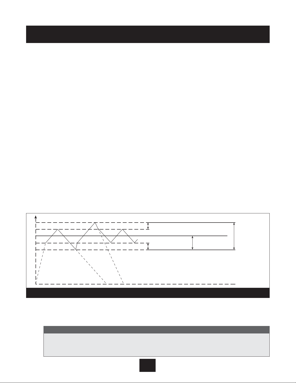
Ramp 1
This ramp is the fast run up time used when the pump first comes on and is trying to reach the
set point. The normal set point for this ramp is 4 seconds for the horse power range 2 through 15
hp. For versions with higher horsepowers, 20 hp and above, the setting should be 10 seconds
minimum. A setting which is too fast may overload the inverter. A setting which is too slow tends
to cause uneven outgoing pressure (pressure drops).
Ramp 2
This ramp is the fast run down time used when the pump is shutting down after demand has
ended. The normal set point for this ramp is 4 seconds for the horse power range 2 through 15
hp. For versions with higher horsepowers, 20 hp and above, the setting should be 10 seconds
minimum. A setting which is too fast leads to pump oscillation or hunting. A setting which is too
slow tends to generate overpressure. Note: air in the pump system can cause a
condition which looks like hunting. Please be sure all air is purged from the system
before trying to change ramp 2.
Ramp 3
This ramp is the slow run up time used when the pump is operating within its set point window
as described above. The normal setting is 50 seconds. A setting which is too slow may cause the
outgoing pressure to drop when demand varies. A setting which is too fast may lead to over
oscillation and inverter overload.
Ramp 4
This ramp is the slow run down time used when the pump is operating within its set point
window. The normal setting is 50 seconds. A setting which is too slow leads to oscillation. A setting
which is too fast delays motor shut down after demand is over.
Maximum Frequency
This setting should match the requirements of the motor being used. If the motor being used is a
60 Hz motor, the setting should be 60 Hz. If the motor is 50 Hz, change this setting to 50 Hz.
62
Operator Custom Features and Displays
Diagram 19
It is possible to set this frequency up to 70 Hz. This is not recommended for standard
pumps. A 10% increase in frequency causes 33% more power draw. Pump and motor warranty will be void if operated above 60 Hz. Check with pump and motor manufacturer first!
Note
PRESSURE
R3
R1
R4
R1
R3
R2
R4
R4
R3
SET HYSTERESIS %
SET HYSTERESIS %
R1: SPEED RAMP FAST INCREASE
R2: SPEED RAMP FAST DECREASE
R3: SPEED RAMP SLOW INCREASE
R4: SPEED RAMP SLOW DECREASE
100%
SET RATED
PRESSURE
WINDOW
SETTING IN % OF
RATED PRESSURE
Page 64

Minimum Frequency
Settings between 0 and 50 Hz are possible. When a minimum frequency is set, the AQUAVAR
II
will
not run the pump below this speed. See the section on submersible pumps, page 44.
Config. F Min
This setting allows you to configure a minimum frequency in one of two ways. If you select “f>0”, the inverter will go down to the minimum frequency and then continue running at that level
for the delay time (see next features). If there is no demand, the inverter will shut off. It will not
ramp down through lower frequencies.
If the selection is “f->f min” the inverter will slow to the minimum frequency but will not stop
unless there is a fault or an external control is connected to terminals X1/4 and X1/5. Caution:
There is a possibility of pump overheating without automatic shut off.
Stop-Delay F Min
This is the delay time in use if “F->0” is set above. If a minimum frequency is set and F->0, then
the AQUAVAR will run down to minimum frequency, for the delay time and then shut down. Delay
time is set in seconds.
Sensor Adjustment
The AQUAVAR
II
controller can automatically calibrate the sensor (transducer or flow meter). Close all
gate valves around the sensor, remove transducer from piping, turn off the pump, and relieve
static pressure so that the sensor reads zero pressure or flow. Press the up and down arrows at
the same time until “
adjusted
” is displayed.
The second sensor adjustment, “
Sensor Curve
,” allows control of linear and quadratic sensors.
Use the linear setting for pressure, differential pressure, level, temperature and flow transmitters.
Use the quadratic setting only for constant flow control with orifice plates and differential
pressure transmitters.
The third sensor adjustment, “
Normalize or Sensor Range
,” allows the maximum pressure or flow
rating to be set for the sensor being used. Refer to the specification sheet for the sensor you are
using to determine the maximum rating at 20mA. Use the up or down arrow to advance to the
correct setting. The standard transducer supplied with the AQUAVARIIcontroller is 25 bar
(362.6 PSI).
Mode
This setting is used to tell the AQUAVAR
II
controller the type of input which will be used to control
the system.
Controller
- Used for a single AQUAVARIIcontrolled pump
Multicontroller
- Used where several AQUAVARIIpumps are connected via RS485
63
Operator Custom Features and Displays
If “Out of Range” is displayed, the system is still under pressure and the transducer cannot be calibrated.
Note
Page 65

Synchronous Controller
- Used for multipump systems where all pumps will run at the same
frequency. (Used for more efficient pump operation.)
Actuator
- Used if you have an external (PID) controller. In this mode the internal controller is
turned off. The output frequency changes proportionally based on sensor input (X1/2) and the
following chart. Low water, thermal protection and external on/off continue to function.
Manual
- When this is used, the required value window in the main menu will change to “manual
control” and the actual frequency and actual value will be displayed (similar to the Jog Mode).
The and keys can then be used to set a specific frequency. If saved, this will become the set
point after power loss.
Start Value
This allows the operator to set a pressure drop from the required value at which the AQUAVAR
II
will
begin to ramp up, when there is demand. For example, if the required value is 50 psi and the
start value is set at 45 PSI, the AQUAVAR
II
will start when system pressure drops to 45 psi. This is
useful when small leaks in the system are causing pressure drops, that cannot be repaired.
Config. Required Value 2
This allows you to select the types of second input value in use in a two value system. Refer to
Section VII.
Relay Config.
This is used to select the function of the output relay for either motor running or slave pump. See
Section IX.
Submenu Offset
A discussion of the various windows and functions of this submenu can be found in Section VIII.
Regulation Mode
The “
Normal
” setting increases the output speed with falling signal (discharge control). The
“
Inverse
” setting decreases the output speed with falling signals (suction control).
Operator Custom Features and Displays
64
▼
▼
Signal
(mA)
20
18
16
14
12
10
8
6
4
2
0
010203040506070
Sensor Fault
Frequency (Hz)
50 Hz 60 Hz
Page 66

Submenu Sequence Control -
for further information see Section IX, page 53
Use this menu to allow starting and stopping of up to 4 pumps with the RS-485 communication
port. The following setup items allow the user to determine when the pumps will start and stop.
Actual Value Increase
Enter a value to increase the setpoint (required value) after a lag pump starts.
Actual Value Decrease
Enter a value to decrease the setpoint (required value) after a lag pump starts. The required value
will be calculated from the following equation after a lag pump starts:
NEW REQUIRED VALUE = REQUIRED VALUE - ACT. VALUE DEC. + ACT. VALUE INC.
For no modification to the setpoint keep both of the increase and decrease values at the same
value.
Enable Sequence Control
Enter the maximum speed prior to starting the lag pump(s). Typically set a +2 HZ below the
maximum frequency. To disable pump staging set this value greater than the maximum frequency.
Switch Interval
Enter the amount of time the lead pump should operate prior to alternating the pump sequence.
This variable allows equal wear on all controlled pumps. Set this value greater than 100 hours to
deactivate alternation.
Source Required Value
Used to set the address for the source of a second required value. May be set to off, ADR1, ADR2,
ADR3 or ADR4.
Submenu Synchronous Control
To use this method of multiple pump control, all pumps must be exactly the same. When the synchronous control is active all of the activated pumps work together to satisfy the required value.
When the synchronous control is deactivated the lead pump(s) run at full speed while the lag
pump modulates in speed to satisfy the required value.
Synchronous Limit
To deactivate synchronous control, set this value below 0 HZ. This will be the lowest speed that
multiple pumps will operate prior to switching off the last pump in sequence. For 60 Hz systems
using synchronous mode, this would normally be set to 40 Hz. This window is also used for the
stop value of a slave pump.
Synchronous Window
This is a frequency offset that increases the synchronous limit that each lag pump is stopped at.
This allows the minimum speed to be increased for each lag pump. For example, if the synchronous limit were set for 40 Hz and the synchronous window is set for 50 Hz. Pump 3 shuts off at
45 Hz and pump 2 shuts off at 40 Hz.
Operator Custom Features and Displays
65
Page 67

Pump Sequence
This screen is located in the Sequence Control Submenu and displays the address and status of
the pump as follows:
AdrX * Pump address 1-4 is displayed as assigned by the operator during system set up. If
the * is displayed, this is the address for this pump.
hold Px The pump is off and the pressure/flow regulator is working.
run Px The pump is running and the pressure/flow regulator is working.
stop Px The pump is stopped and the pressure/flow regulator for this pump is blocked.
disabled The AQUAVAR
II
controller is not ready to start (Autostart on the main menu is off).
error There is a fault in the AQUAVARIIcontroller operation. This will be identified in the
error displays (see pages 67-68).
fault There is a problem with communication to other pumps via the RS-485 connection.
detected Communication with other pumps via the RS-485 connection is enabled.
Bus ARBIT
The Data Bus Diagnostic display is a warning which shows the number of attempts used by the
RS-485 interface to synchronize the pump controllers in the system. In a multiple pump system,
each AQUAVAR
II
controller must be set to the same operating parameters. If this is not the case, or
if there is some mechanical or electrical block to the signal, the display will indicate a fault. To
clear the display, unplug the AQUAVAR
II
controller for about one minute.
Pump - Address
If only one unit is used the proper setting is “OFF”. If 2 through 4 units are installed, each pump
must be assigned a unique address number.
ADC Reference
This setting tells the unit where to look for the actual value signal. Set to “LOCAL” if the actual
value is obtained from a 4-20mA transmitter wired to the unit’s actual value input terminals (X1:
2, 3). Set to “REMOTE” if the actual value is obtained from the RS-485 port via a remote device.
Frequency Lifting
Allows modification of the required pressure to accommodate for system frictional losses due to
increased flow. Enter the speed at which system losses are a concern and compensation should
begin to be added to the required pressure. Typical settings are 40 HZ for a 60 HZ motor and 30
HZ for a 50 HZ motor. See section III for more information.
Lift Intensity
Enter a value for increasing the required pressure due to frictional losses once the frequency lifting
speed is exceeded. Calculate the pressure drop due to frictional losses and divide by the required
pressure and input this value as a percentage. Enter 0% if frictional losses are of no concern.
Reference
This display is located in the RS-485 Submenu and shows whether control is being received from
the local ADC (Analog/Digital Converter) or from another source shown as “
SIO
” via the RS-485
interface.
66
Operator Custom Features and Displays
Page 68

Analog Out
It is possible for the AQUAVAR
II
controller to supply an output signal from 0-10 Volts at a maximum
of 2 mA. Connection of the outside recording device (such as a meter) is done at terminals 1
(analog return) and 2 (output signal) of terminal strip X9 inside the AQUAVAR
II
controller drive.
The
“Analog Out”
display allows you to display pressure as the output to be displayed. 0-10
Volts equals 0-100% of displayed pressure.
Pressure Units
This display allows the user to select Bar, PSI, or meters of water for pressure or gallons per
minute for flow, or percent. If percent is selected, the percentage displayed will be the percentage
of the maximum sensor value.
Test Run
The AQUAVAR
II
controller can carry out a test run of the pump either automatically or manually. For
automatic settings, enter the number of hours you want to elapse between the last pump shut
down and the test. Possible settings are between 10 and 100 hours. When the time has elapsed,
the pump will automatically turn on at 50% of maximum frequency (normally 30 hz) for 20
seconds and then turn off again.
Submenu Test Run Manual
To conduct a manual test run of the pump, enter this submenu by holding down on the S key. The
first display in the submenu is the activation display for the test run. To start the test, press the up
and down arrow keys at the same time. If you want the test to be conducted at some other
frequency than 30 hz, use the next display in the submenu:
Test Frequency
. This can be set
from 6-60 hz. When finished, hold down on the button until the display returns to the
Submenu display.
Submenu Errors
Two of the functions in this submenu have been covered: Conveyor Limit (used to set system shut
off when maximum flow is exceeded) and Delay Time (used to set pump shut off in conjunction with
conveyor limit and a suction side pressure switch or float). The remaining displays in this submenu
are used to show the cause of failure in the last three instances where a pump or system failure
caused the AQUAVAR
II
controller to turn the pump off.
Within the Error Submenu, the Error Reset display allows the operator to tell the AQUAVAR
II
controller to re-try pumping after a non-fatal fault. When turned on, the AQUAVARIIcontroller will
retry up to five times before shutting the unit off. If Error Reset is off, the AQUAVAR
II
controller will
shut down the system the first time a fault occurs. In both cases, the AQUAVAR
II
controller can be
67
Operator Custom Features and Displays
This will only work when the Auto Start function on the main menu is on. If you do not want to
use the automatic test run function, you can turn it off by selecting 100 hours, and then pressing the up and down arrows at the same time until the display changes to deactivated.
Note
*
Page 69

reset by removing all power to the unit for at least one minute. This will reset the fault counter to
zero. NOTE: Error reset will not apply to “Low Water Switch” on terminals X1, 6 and 7. If this
contact is “Open”, the AQUAVAR will stop after the delay time.
Clear Errors
This display allows you to clear all error memory by entering a password. Enter 0726 in “Clear
Errors” screen and press “ ” key.
Operating Hours
This counter displays the total amount of time that the AQUAVAR
II
controller drive head has
operated, (whether the pump was running or not). This time can be reset to zero by pressing the
up and down arrows at the same time for 25 seconds.
Total Run Time
This display shows the total run time of the pump motor in hours and minutes. This display resets
automatically when Operating Hours is reset.
Display Contrast
This display allows the operator to set the contrast of the LCD display on the control panel from
10% to 100%. Use the up and down arrows to set the contrast desired.
Set Password
The pre-set factory password is 0066. This display allows you to create a new password for
security. If you decide to change the password, write it down and store it in a safe place.
Lock Function
This allows the operator to lock all of the settings on the main menu except On/Off. When the
lock function is off, main menu settings may be changed normally. On pre-packaged systems, the
lock function will assure that package settings remain as selected at the factory.
Default Values
Default values can be set for either US or Europe base data. The US default is PSI, 60 Hz, etc. To
return all settings to the pre-programmed factory settings: press the up and down arrow keys
at the same time and hold them as a count down timer counts back from 5 to 0. When complete,
the display will return to the main menu and show Inverter - Stop/Default. All settings can be
entered again following the directions given in the Programming Section. After loading default
values, the screen will flash until values are saved.
Save ??
This display allows any program changes to be saved and return to the main menu. Remember
that all program changes will be cancelled when the system is turned off unless these are
saved.
Operator Custom Features and Displays
68
YOUR GOULDS DISTRIBUTOR OR APPLICATION ENGINEER WILL NOT BE ABLE TO HELP
YOU WITH PROGRAMMING PROBLEMS IF YOU HAVE CHANGED THE PASSWORD AND
LOST IT!
NOTE
*
Page 70

Lack of Water
This error message will be displayed when a switch has indicated that the incoming water pressure
or water level in a suction tank falls below the required NPSH of the pump. If suction conditions
appear to be correct, check the pressure switch or float switch to make sure it is operating properly. When the suction conditions have returned to normal, the pump will restart automatically. This
message will also appear if terminals 6 and 7 on terminal block X1 are not bridged.
Conveyor Control (Value Range Control)
The drive is not able to obtain the minimum required value set in the conveyor limit setting. Look
for potential reasons for the low signal or lower the “CONVEYOR CONTROL” or increase the
“DELAY TIME” settings.
Error 1 through Error 8
These are program errors within the AQUAVAR
II
controller control system. If one of these errors
occurs, turn the unit off for at least 30 seconds and then back on. If the error is displayed again,
contact your Goulds Pumps AQUAVAR
II
distributor with an exact description of the fault.
Error 1 Eprom Error
Error 2 Security Software Protection Error
Error 4 Keyboard Error, check pushbuttons for proper actuation, or buttons may be held
down by the cover being on too tight.
Error 5 Eprom Error
Error 6 Watchdog Error
Error 7 Processor Pulse Error (Failure of oscillator for processor)
Error 8 Invalid Processor Command Error, power wires and motor leads may be too close
to the control board or communication ribbon.
Pressure Sensor Error
The pressure or flow sensor is out of order, not connected properly, not zeroed properly, or the
cable is damaged. Check the sensor and zero object and then turn the unit back on.
Actual Value Sensor Error (Act. Val. Sens. Error)
The AQUAVAR does not receive a 4-20 mA signal from transmitter. Check transducer wiring, connections and for the 4-20 mA signal. Once corrected, turn power off for at least 30 seconds to restart.
Inverter Error
A problem or error has occured in the internal drive. Check the active fault history on internal
display, page 70. Press SHIFT + ENTER keys to read fault history and fault codes, Diagram 20,
page 70, for list of fault codes.
69
DISCONNECT POWER FROM THE AQUAVAR CONTROLLER BEFORE CONNECTING THE FAULTS TO AVOID POTENTIAL FOR AUTOMATIC PUMP RESTART.
WARNING
Repair of Faults and Errors
WARNING
Hazardous
voltage
Page 71

External Device Error
This indicates that there is an electrical problem with the input line, drive or pump motor.
To determine the exact problem, open the front panel door and read the error message on
the internal display.
Active Fault/Warning and Fault History Mode
When a fault or warning occurs, the Operate mode automatically changes to the Active Fault
mode. The drive stores up to three active faults or warnings and provides a separate display for
each. Diagram 20 provides a sample display for an active fault.
Once the active fault display is shown, you must correct the condition causing the fault and then
reset the drive to return to the Operate mode. However, if all three active fault displays only show
warnings, you may return to the Operate mode by pressing SHIFT + ENTER.
In addition to the active faults, the drive maintains a history of faults. The three most-recent faults
are kept in the fault history log. The log is accessed by pressing SHIF T + ENTER. As shown in
Diagram 20, the display is the same as for active faults, except that an H is shown in the upper left
corner. (See Table 13 for a description of fault codes.)
After viewing the fault history log, return to the Operate mode by pressing PROG twice.
Table 13: AQUAVARIIElectrical Fault Codes
Fault Code Fault Name Possible Cause(s) How to Recover
01 Watch Dog Trip Consult Factory Consult Factory
02 Power Bridge ID • Ribbon cable not correctly • Ensure that the ribbon cable is
seated between the power correctly seated.
and control boards. • Determine the source of the
• Electrical noise. noise and eliminate it.
03 Current Calibr Current sensors have an Consult factory.
offset problem.
70
Repair of Faults and Errors
Diagram 20
Display for Active Faults and Warnings Display for Fault History
(1 denotes the first, most-recent fault or warning)
Indicates which display is shown
A1 FAULT #12
GROUND FAULT
Name of fault or warning
Indicates which display is shown
(3 denotes the oldest fault)
H3 FAULT #12
GROUND FAULT
Name of fault or warning
Page 72

Table 13: AQUAVAR Electrical Fault Codes (continued)
Fault Code Fault Name Possible Cause(s) How to Recover
04 TSP 24V Supply Overloaded +24 Vdc supply. Check the loading on the +24
Vdc supply and remove any
excess load.
05 DC Volt Calibr DC voltage is outside of normal • Check line voltage.
limits on power-up. This may • Check the Supply Voltage
be caused by: parameter.
• High or low line voltage.
• Supply voltage parameter
incorrectly set.
06 IOC Trip Output short-circuit. May also • Check motor wiring.
be caused by a ground fault • Extend acceleration ramp.
(see Fault Code 11 below). • Reduce boost.
• Check for ground faults.
07 Ext Flt/Warning The configured input sensed an Investigate why the external fault
(Fault) external fault. occurred and correct.
09 Inter-Proc Comm Loss of communication with Reset the drive by pressing the
the control terminal strip. Stop key for more than 1 second.
If problem persists, consult the
factory.
11 Ground Fault The drive detected that the sum • Check motor wiring.
of the motor phases’ current is • Check for and remove any
not zero. This may be caused capacitive load.
by insulation failure in the • Check the motor and cabling
motor or the cables. for shorts to ground.
12 Input Phase Loss Current measurement detected Check input power cables.
an input phase with no current.
13 Overvoltage The voltage of the internal DC- • Adjust deceleration time.
link has exceeded 135% of the • Add dynamic braking module.
Nominal voltage. This may be
caused by incorrect deceleration
time or high overvoltage spikes
on line.
14 Under Voltage The DC bus voltage fell below Reset fault and attempt to restart.
65% of the nominal voltage. This Check the line for proper supply.
may be due to line supply failure If fault persists, an internal fault
or internal failure of the drive. has occurred; contact the factory.
Repair of Faults and Errors
71
Page 73

Repair of Faults and Errors
72
Table 13: AQUAVAR Electrical Fault Codes
(continued)
Fault Code Fault Name Possible Cause(s) How to Recover
16 Motor Over Temp The drive’s motor temperature Decrease motor loading. If the
(Fault) model detected motor motor is not overheated, check
overheating severe enough to the temperature model
cause a fault. parameters.
17 Output Fault The output sensor detected • Check motor wiring.
an error. • Check for and remove any
capacitive load.
• Check the motor and cabling
for shorts to ground.
18 Overcurrent The drive has measured • Check the load, motor size,
excessive current in the motor and cables.
output. This may be caused by: • Review the settings for
• Sudden, heavy load increase. acceleration and deceleration
• Short circuit in the motor times.
cables.
• Unsuitable motor.
19 Drive Over Temp Temperature of the drive’s • Check the air flow.
heatsink is too high. • Check that the heatsink is not
clogged.
• Check the ambient
temperature.
• Check that the switching
frequency is not too high
compared to ambient
temperature and load.
20 Motor Overload Excessive load on the motor Check the motor and load.
(for example, a jammed load.)
21 Drive Under Temp • Temperature of the drive’s • Increase the ambient
heatsink is below 0ºC (32ºF). temperature.
• Ribbon cable not correctly • Ensure that the ribbon cable is
seated between the power correctly seated.
and control boards.
22 Motor Stall The motor’s stall protection Check the motor.
(Fault) sensed a stall severe enough
to cause a fault.
Page 74

Table 13: AQUAVAR Electrical Fault Codes (continued)
Fault Code Fault Name Possible Cause(s) How to Recover
23 Motor Underload The load on the motor is so Check the motor and load.
insufficient (for example, a
broken conveyor belt) that a
fault occurs.
24 TSP 10 V Ref 10 V reference for the analog • Ensure that the total load on
input is overloaded. the +10 terminal does not
exceed 20 mAdc.
• Check for correct connection of
devices to the +10 terminal.
• Check for short circuits
associated with devices
connected to the +10 terminal.
• Consult factory.
25 EE Ref Checksum Parameter restoring error due Reset the fault and attempt a
to interference fault or restart. If fault persists, contact
component failure. the factory.
26 EE Par Checksum Parameter restoring error due Reset the fault and attempt a
to interference fault or restart. If fault persists, contact
component failure. the factory.
27 EEPROM Parameter restoring error due Reset the fault and attempt a
Checksum to interference fault or restart. If fault persists, contact
component failure. the factory.
28 Outpt Phase Loss Current measurement detected Check motor cables.
a motor phase with no current.
29 Precharge Fault Consult factory. Consult factory.
30 TRIN Flt (ASIC) Consult factory. Consult factory.
31 Satur Flt (ASIC) Consult factory. Consult factor y.
32 Empty Trp (ASIC) Consult factory. Consult factory.
33 Appl Change Consult factory. Consult factor y.
34 High Unbal Curr Consult factor y. Consult factory.
35 MCP Software Consult factory. Consult factor y.
36 Loss of Ref The drive detected the loss of Restore the reference signal.
(Fault) the reference signal.
37 Loss of Ref The drive detected the loss of Restore the reference signal.
(Warning) the reference signal.
38 Broken Wire Trip The drive detected a broken Check the control wiring for a
(Fault) wire to Analog Input 1. broken wire and replace.
39 Broken Wire Trip The drive detected a broken Check the control wiring for a
(Warning) wire to Analog Input 1. broken wire and replace.
Repair of Faults and Errors
73
Page 75

Repair of Faults and Errors
Table 13: AQUAVAR Electrical Fault Codes (continued)
Fault Code Fault Name Possible Cause(s) How to Recover
40 Loss of Keypad Communication with the keypad Investigate and correct
is lost while keypad control is communication problem.
active.
41 Ext Flt/Warning The configured input sensed an Investigate why the external fault
(Warning) external fault.
42 Ser Lnk TimeOut The watchdog timer for Modbus Reset and restore serial link
serial communications timed out. communications.
43 DI Logic Not Set DI active logic is not set. Set DI active logic via Active
Logic parameter.
44 DI Logic Changed Consult factory. Consult factor y.
50 Fan Fault The cooling fan on the drive’s Remove obstruction.
enclosure is drawing too much
current, which may indicate that Replace fan.
the fan is jammed or has failed.
51 Fan Warning The cooling fan on the drive’s Remove obstruction.
enclosure is drawing excessive
current, but not enough to
generate a fault. This may
indicate that the fan is jammed.
52 Motor Over Temp The drive’s motor temperature Decrease motor loading. If the
(Warning) model detected motor motor is not overheated, check
overheating, but not severe the temperature model
enough to generate a fault. parameters.
53 Motor Stall The motor ’s stall protection Check the motor.
(Warning) sensed a stall, but not severe
enough to cause a fault.
54 Motor Underload The load on the motor is Check the motor and load.
(Warning) insufficient, but not so low that
a fault occurs.
55 DeviceNet No DeviceNet communication Reset and restore DeviceNet
Timeout (Fault) has occurred in the specified communication. See the
amount of time, and a fault DeviceNet manual for further
occurs. information.
56 DeviceNet No DeviceNet communication Reset and restore DeviceNet
Timeout has occurred in the specified communication. See the
(Warning) amount of time, and a warning DeviceNet manual for further
occurs. information.
57 Network Ext Fault The external communication Reset and restore DeviceNet
network delivered a command communication.
to the drive that is forcing a
system-wide error.
58 Ser Lnk TimeOut The programmed value of Reset and restore serial link
(Warning) parameter Comm Timeout communications.
was exceeded.
74
Page 76

75
AQUAVAR Controller Flow Chart
Diagram 21
REQUIRED
VALUE
126.9 PSI
Auto-START
ON
ERROR 1 ERROR 2 ERROR 3 ERROR 4 ERROR 5
TOTAL RUN
TIME
0000: 41
SAVE ??
– + v
PASSWORD
0000
JOG-MODE
XX Hz
XX PSI
WINDOW
5%
RAMP
HYSTERISIS
80%
RAMP 1
4.0 Sec.
RAMP 2
4.0 Sec.
RAMP 3
70 Sec.
RAMP 4
70 Sec.
MAX.
FREQUENCY
60.0 Hz
MIN.
FREQUENCY
0.0 Hz
CONFIG.
FMIN
F -> 0
STOP–
DELAY FMIN
0 Sec.
SENSOR–
ADJUST
out of range
SENSOR–
CURVE
Linear
NORMALIZE
20 mA –
362.6 Bar
REGULATION
MODE
Normal
START
VALUE
Disabled
CONFIG. REG.
Val. 2
OFF
RELAY
CONFIG.
Run
Motor
MODE
Multi-
Controller
SUBMENU
Seq. Control
SUBMENU
RS485–
Interface
FREQU. –
LIFTING
37.0 Hz
LIFT
INTENSITY
0.0%
DIMENSION
UNIT
PSI
SUBMENU
TEST RUN
xxx
SUBMENU
ERRORS
ANALOGUE –
OUT
Actual Value
SUBMENU
Offset
TEST RUN
after 100 h.
OPERATING
HOURS 0000 h.
Control unit’s
operating time
DISP.–
CONTRAST
50%
SET
PASSWORD
xxxx
LOCK
FUNCTION
OFF
SUBMENU
DEFAULT
VALUES
SAVE ??
– + v
PUMP
ADDRESS
OFF
ADC
REFERENCE
Local
CONVEYOR–
LIMIT
disabled
DELAY
TIME
2 sec.
ERROR–
RESET
disabled
CLEAR
ERROR
0000
DEFAULT
EUROPE
– + v
DEFAULT
USA
– + v
TEST RUN
Man.
– + v
TEST –
FREQUENCY
30.0 Hz
ACTU. VALUE
INC.
5.0 PSI
ACTU. VALUE
DEC.
2.1 PSI
ENABLE
SEQ. CTL.
58.0 Hz
SWITCH
INTERVAL
12 hours
SUBMENU
Synch.
Control
BUSARBIT –
DIAG.
0
SOURCE
REQ. VALUE
ADR1
PUMP
SEQUENCE
Adrl disabled
LEVEL 1
2.0%
LEVEL 2
0.0%
INTENSITY 1
0.0%
INTENSITY 2
0.0%
SYNCHRON.
LIMIT
0.0 Hz
SYNCHRON–
WINDOW
2.5 Hz
OFFSET –
INPUT
OFF
SW Ver.
Date:
ITT Ind.
50 PSI
Press • long
Page 77

You can access a help display at any time by pressing the “ “ and keys at the same time. This
will change the second line of the window to a “running” text which provides more information about
the window function. The following list shows the normal window text and the available help text.
(NOTE: You can access this help text in any program window, hold “ “ and keys!)
76
Help Windows
Window text Help Text
No Autostart ITT Industries Spanish > Inc.; English > Dec; French > Select,
Disable Inverter X.XX PSI to change language, see page 28 “Note”.
Required Value Input Required Pressure / Flow for
X.XX PSI Value #1 or Value #2.
Auto-Start ON > Autostart enable; Off Autostart disable.
Off (Default) Default is “ON”, allows auto operation of AV II.
Error Last Error the unit has experienced.
1
Error 4th recorded error.
2
Error 3rd recorded error.
3
Error 2nd recorded error.
4
Error 1st recorded error.
5
Total Run Time Total motor run time hh:mm.
0000:00
Save ??? Press INC + DEC to save parameter values.
Inc + Dec Always save changes to programming.
Password Enter Password.
0000 Default is 0066.
Jog Mode Jog Mode: frequency controlled by Inc or Dec.
0.0Hz XX.XX PSI Displays the motor frequency and pressure for
manual control of motor, press the up arrow or
down arrow.
?
*
▼
*
▼
Page 78

77
Help Windows
Window text Help Text
Window Pressure window, percentage above and
5% below set pressure. See pages 61 and 62.
Ramp Hysteresis Hysteresis, part of the window.
50% See pages 61 and 62.
Ramp 1 Ramp 1: fast acceleration time. (Ramp up speed.)
4.0 Sec See page 62. Set higher for larger HP motors.
Ramp 2 Ramp 2: fast deceleration time. (Ramp down speed.)
4.0 Sec. See page 62. Set higher for larger HP motors.
Ramp 3 Ramp 3: slow acceleration time.
50 Sec. See page 62.
Ramp 4 Ramp 4: slow deceleration time.
50 Sec. See page 62.
Max. Frequency Maximum output frequency
60.0 Hz range: 6 - 70 Hz, see page 62.
Min. Frequency Minimum output frequency (range: 0 - max.
0.0 Hz frequency). See pages 43 and 63.
Config. F Min Configuration behavior at
f->0 or f->F Min minimum frequency, see page 63.
Stop-Delay Time Delay for pump stop when
0 Sec. f->0 is chosen, see page 63.
Sensor Adjust? Sensor zero adjustment (press inc + dec).
Out of Range See page 63.
Sensor Curve Sensor characteristic curve (linear is default).
(Linear or Quadratic) See page 63.
Sensor Range Normalize to maximum sensor value, adjust to
20mA = 25.0 bar (367.6 PSI) sensor’s maximum value. See page 63.
Mode: Mode: controller > pressure control;
Controller Actuator > frequency set point as ADC Value
Multicontroller > control of up to 4 pumps.
Synchronous > All motors synchronized for
same speed operation. See page 64.
Page 79

78
Help Windows
Window text Help Text
Regulation Mode (Normal Default) Pumping regulation mode, normal or inverse.
See page 64.
Start Value Start value, allows pressure to drop in system
PSI or Selected Units before unit starts. (Disabled is default) See page 64.
Config. 2nd Required Value Configuration of a second value from another
Off (Default) sensor. See page 64.
Relay Configuration Relay configuration. See page 64.
Run Motor (Default)
Submenu Submenu offset: to enter push “ “ key
Offset for at least two seconds.
Offset Input Selection of offset input, if required.
Off (Default) See page 49.
Level 1 Start level for offset 1.
XX.X % See page 50.
Level 2 Start level for offset 2.
XX.X% See page 50.
Intensity 1 Intensity of offset 1.
XX.X% See page 51.
Intensity 2 Intensity of offset 2.
XX.X% See page 51.
Submenu Submenu seq. control; to enter push “ “ key
Seq. Control for at least two seconds. See pages 52 and 53.
Pressure Incr. Pressure increment at switching of additional pumps
4 PSI in multicontroller mode. See pages 52 and 53.
Pressure Dec. Pressure decrement for consecutive pumps.
4 PSI See pages 52 and 53.
Enable Seq. Ctl. Frequency limit enable sequence control. Starts
58 Hz (Default) second pump in multicontroller. See page 55, step 9.
Switch Interval Time interval pump sequence change. Allows
12h (Default) multiple pumps to lead/lag in system, based on
switch interval time. See page 55, step 10.
*
*
Page 80

79
Help Windows
Window text Help Text
Submenu Submenu: synchronous regulation; to enter
Synch. Control push select at least one second. See page 56.
Synchron Limit Frequency limit to enable the synchronous
35.0 Hz regulation. See page 56, step 11.
Synchron Window Frequency offset for the frequency limit which
5.0 Hz activates the synchronous regulation. See page 56.
Pump Sequence Diagnostics: Pump sequence and status. Identifies
Adr 1 Hold P1 address numbers and pump numbers in multi-
controller mode and synchronous mode.
BUSARBIT DIAG Diagnostics: Bus arbitration (this pump).
0 Diagnostics only, do not adjust.
SUBMENU Submenu: Serial Interface; to enter push “ “ key
RS485 Interface for at least two seconds.
Pump Address SIO address of the pump, for addressing each
Off AV II in multicontroller mode.
ADC Reference Pressure or frequency reference enabled by local
Local (Default) ADC or by SIO.
Frequency Lifting Frequency limit for pressure lift.
30.0 Hz
Lift Intensity Max. lift in % of pressure set point at max.
0.0% frequency.
Analog Out Meter output: frequency; pressure.
Actual Value
Dimension Unit Displayed dimension unit.
PSI
Test Run Time interval for test run 10 - 100 hr. or
After 24 h deactivated (inc+ dec).
Submenu Submenu pump test manual; to enter push
Test Run Man. select at least one second.
*
Page 81

80
Help Windows
Window text Help Text
Test Run Man. Start test run with up and down arrows
(Inc + Dec) simultaneously.
Test Frequency Test frequency. Frequency at when motor
30.0 Hz will run in test mode.
Submenu Submenu: errors; to enter push “ “ key
Errors for at least two seconds.
Conveyor Limit Value at which pump system shall be deactivated,
due to lack of NPSH or system pressure.
Delay Seconds Enter a time the pump is allowed to run after a
Disabled (Default) suction line sensor has activated, or conveyor
limit has been reached.
Error Reset Automatic error reset measured in seconds. The
On AV II will restart 5 times. If error is still present,
the AV II will stay off on faults.
Clear Errors Clear error histor y, enter 0726
0000 and press the “ ” key.
Operating Hours Total AQUAVAR controller operating time
xxxxh (reset counters: press the up and down arrows).
Disp. Contrast Display contrast, 0-100% contrast.
100%, 50% Default
Set Password Modify password enables the user to set a new
0000 password.
Lock Function On > keypad locked: off > changes allowed.
Off
Submenu Submenu load default parameters to enter
Default Values push select at least 1 second.
Default USA/Europe Reset to default parameters for US or European
Press up and down arrows (if needed). settings.
Save ??? Press Inc + Dec to save entered values
Inc + dec
*
*
Page 82

Series 1200
81
Appendix A
Diagram 22
Pressure Transducer Data
Specifications
Measuring Range (FS): .52 bar 10 bar 25 bar
(other ranges upon request)
Over-Pressure (PMAX): 2 bar 40 bar 100 bar
Class of protection: IP 65 (Nema 4)
Type Sealed gauge:
Output-Signal: 4-20mA; 2 wire
Supply: 7-35 VDC
Linearity: 0.5% FS
Stability: 0.2% FS max.
Total Error: 2% FS
Operating Temperature: -22°F to 260° F
Material: Body and diaphragm: 17-4 PH
3.45
1
⁄4” NPT
1.07
3
⁄4” HEX
Page 83

Differential
Pressure Transmitter
Series PD-39S
The sensors of this differential transmitter are two
piezoresistive silicon pressure sensors, mounted
on a tape (TAP), freely floating in an oil chamber.
The pressure is transferred to the sensor by a
separating steel diaphragm in the oil chamber.
82
Appendix A
Specifications
Measuring Range (FS): 0,4 bar 4 bar 10 bar
Differential
(other ranges upon request)
Over-Pressure (PMAX): 16 bar 16 bar 16 bar Single-sided
Class of protection: IP 65 IP 65
Type Sealed gauge:
Output-Signal: 4-20mA ; 2 wire
Supply: 8-28 VDC
Load resistance: max. 50Ω at supply voltage = 10VDC
Linearity: ± 0.2% FS; max ±0.5% FS
Stability: ± 0.1% FS; max ± 0.2% FS
Operating Temperature: -20° to +80° C
Storage Temperature: -40° to +120° C
Material: Body and diaphragm: 1.4435 stainless steel
Screw joint and cover:
Diagram 23
Plug: mPm 193
incl. 2 m cable
Cable:
Out (white)
+ Vcc (brown)
Screen
44
60
26
40
P -
P +
= 95
Page 84

83
Model Delta 692
Differential Pressure
Transducer and Orifice Plate
Appendix A
Diagram 24
Specifications
Standard 80096 ND
Range (FS)” 2, 5 bar - 37 PSI
Over Pressure (PMAX) 12 bar - 177 PSI
Signal over Range 4... 20mA; 2 wire
Power Supply 9... 33 volts DC
E1 Connection DIN-plug 43650
Diagram 25
Hydraulic connection R 1/8"
Linearity tip± .25%FS; max.±.5%FS
Stability tip± .1%FS; max.±.5%FS
Operating
Temperature -15° - 80° C
Storage
Temperature -15° - 80° C
Materials Stainless steel (body)
Ceramic (diaphragm)
Diagram 26
Nominal Pipe/ Constant
Discharge Size Flow Range
1" 12-35 GPM
1" 18-52 GPM
1
1
/
2" 20-62 GPM
1
1
/2" 32-90 GPM
2
1
/2" 35-105 GPM
2
1
/
2" 52-160 GPM
3" 52-160 GPM
3" 70-210 GPM
3" 120-350 GPM
1 P1 Pressure high (+)
2 P2 Pressure low (-)
3 gaskets
4 ceramic component
5 ventplug
Pressure Transducer Data
1
P1
P2
2
3
4
5
OUT
IN +
2
3
1
supply
2-wire
Page 85

Interpreting Model Numbers
The model number of the AQUAVAR appears on the shipping carton label and on the technical data
label affixed to the model. The information provided by the model number is shown below:
A
V2 V 20 010 D
AV Series
Torque
C = Constant Torque
V = Variable Torque
Input Voltage
2S = 230 Vac, single-phase
20 = 230 Vac, three-phase
40 = 460 Vac, three-phase
50 = 575 Vac, three-phase
Horsepower Rating
For example, 010 = 1 HP
Enclosure
D = NEMA 12 / IP55, with keypad
N = NEMA 4 or NEMA 3R
Power and Current Ratings
Motor Power Input
Maximum Load
Maximum
Output
Output Current (A)
Model
HP kW
Voltage
Current (A)
Voltage
200/380 230/460/
Number
(V ac)
200/380 230/460/
(V ac)
Vac 575 Vac
Vac 575 Vac
AV2V2S010D 1.0 0.7 — 8.9 4.8 4.2
AV2V2S020D 2.0 1.5 — 16.2 7.8 6.8
AV2V2S030D 3.0 2.2
Single-phase
— 23.1
0 to 230
11.0 9.6
AV2V2S050D 5.0 3.7
200 to 230
— 32.9 17.5 15.2
AV2V2S075D 7.5 5.5
±15%
— 47.5 25.3 22.0
AV2V2S100D 10.0 7.5 — 62.8 32.2 28.0
AV2V20010D 1.0 0.7 5.6 4.8 4.8 4.2
AV2V20020D 2.0 1.5 9.0 7.8 7.8 6.8
AV2V20030D 3.0 2.2
Three-phase
12.7 11.0
0 to 230
11.0 9.6
AV2V20050D 5.0 3.7
200 to 230
20.2 17.5 17.5 15.2
AV2V20075D 7.5 5.5
±15%
29.2 25.3 25.3 22.0
AV2V20100D 10.0 7.5 37.2 32.2 32.2 28.0
Technical Characteristics
84
Page 86

Technical Characteristics
85
Power and Current Ratings
(continued)
Motor Power Input
Maximum Load
Maximum
Output
Output Current (A)
Model
HP kW
Voltage
Current (A)
Voltage
200/380 230/460/
Number
(V ac)
200/380 230/460/
(V ac)
Vac 575 Vac
Vac 575 Vac
AV2V20150D 15.0 11.0 Three-phase 200 52.1 46.4
0 to 230
48.3 42.0
AV2V20200D 20.0 15.0 to 230 ±15% 53.9 47.4 62.1 54.0
AV2V40010D 1.0 0.7 3.4 2.4 2.4 2.1
AV2V40020D 2.0 1.5 5.2 3.9 3.8 3.4
AV2V40030D 3.0 2.2 7.2 5.6 5.7 4.8
AV2V40050D 5.0 3.7 12.0 8.8 8.9 7.6
AV2V40075D 7.5 5.5 15.0 12.8 12.0 11.0
AV2V40100D 10.0 7.5 19.7 16.3 15.6 14.0
AV2V40150D 15.0 11.0 30.9 25.8 23.0 21.0
AV2V40200D 20.0 15.0 Three-phase 40.0 33.3 31.0 27.0
AV2V40250D 25.0 18.6 380 to 460 49.2 40.0 0 to 460 37.0 34.0
AV2V40300D 30.0 22.0 ±15% 57.5 47.8 43.0 40.0
AV2V40400D 40.0 30.0 62.3 53.3 61.0 52.0
AV2C40500D 50.0 37.0 71.0 65.0 71.0 65.0
AV2C40600D 60.0 45.0 86.0 77.0 86.0 77.0
AV2C40750D 75.0 55.0 105.0 96.0 105.0 96.0
AV2V40500D 50.0 37.3 69.0 58.0 73.0 65.0
AV2V40600D 60.0 44.7 82.0 68.8 87.0 77.0
AV2V40750D 75.0 56.0 98.3 82.2 105.0 96.0
AV2V50010D 1.0 0.7 — 2.0 — 1.7
AV2V50020D 2.0 1.5 — 3.6 — 2.7
AV2V50030D 3.0 2.2 — 5.0 — 3.9
AV2V50050D 5.0 3.7 — 7.6 — 6.1
AV2V50075D 7.5 5.5 — 10.4 — 9.0
AV2V50100D 10.0 7.5 — 14.1 — 11.0
AV2V50150D 15.0 10.0 Three-phase — 20.8
0 to 575
— 17.0
AV2V50200D 20.0 15.0 575 ±15% — 27.8 — 22.0
AV2V50250D 25.0 18.6 — 33.4 — 27.0
AV2V50300D 30.0 22.0 — 39.1 — 32.0
AV2V50400D 40.0 30.0 — 52.0 — 41.0
AV2C50500D 50.0 37.0 — 52.0 — 52.0
AV2C50600D 60.0 45.0 — 62.0 — 62.0
AV2C50750D 75.0 55.0 — 77.0 — 77.0
(1) Consult factory.
Page 87

Power and Current Ratings
(continued)
Specifications
Environmental MAXIMUM HEATSINK TEMP. = 100º C (212º F)
Operating temperature 0ºC to +40ºC (32ºF to 104ºF) *
Storage temperature -20ºC to +65ºC (-4ºF to 149ºF)
Humidity 0% to 95% non-condensing
Altitude 1000 m (3300 ft) without derating *
Acoustic noise 80 dBA sound power at 1 m (3 ft)
Electrical
Voltage input AV2C2x models: 200 to 230 Vac, ±15%
AV2C4x models: 380 to 460 Vac, ±15%
AV2C5x models: 575 Vac, ±15%
Input Line frequency 50 / 60 Hz ±2 Hz
Overvoltage trip 407 Vdc 814 Vdc 1017 Vdc (DC BUS Voltage)
Undervoltage trip 202 Vdc 404 Vdc 505 Vdc (DC BUS Voltage)
Output voltage 0 to 100% of line voltage, 3 Phase
Overload capacity 110% of rated rms for 60 seconds
Rated output frequency 50/60 Hz ±5%
Timed overload Adjustable time trip set for 110%
of rated motor current
Agency listing UL and CUL Listed, CE marked
Control Features
Protective features Overcurrent, overvoltage, phase loss, motor overand circuits temperature, overtemperature, ground fault,
undervoltage, short circuit, sensor fault.
* For high ambient temperatures, derate HP of drive. Altitudes above 3300 ft. of sea level,
derate 2% of HP for every 1000 ft. above 3300 ft. Consult factory for assistance.
Technical Characteristics
86
Page 88

AQUAVAR Controller Drive Head Technical Data and Terminals
Terminals: There is a terminal strip inside the AQUAVAR controller which will allow the
connection of a wide range of external devices for display or control. When
using these terminals, shielded wires need to be used. Unshielded wires may
produce signal interference which will affect the inverter.
X1 1 Ground connection
2 Actual value input 4- 20 mA, 50 ohm load resistance. Used to connect external
pressure transducer, flow meter, etc. Can also be used as input source from
another device signalling actual speed when “actuator ” is selected in
controller mode.
3 Power source for external transducer 15 V DC, max. 25 mA
4 Ground connection for external on/off
5 External on/off connection, 10 kOhm resistance, 5 VDC gold plated contact.
Note that the external device must have a switch suitable for < 10 V. If no
outside panel or control is used, a jumper wire is installed on contacts 4 and
5.
6 Ground connection for low water switch.
7 Low water switch connection, 10 kOhm resistance, 5 VDC. This contact is
where an external level switch, float switch or pressure switch from the suction line would be installed. If no suction pressure devices are used, a jumper
wire is installed on contacts 6 and 7.
8 5 V power source for the Klixon thermoswitch mounted in the motor conduit
box. 10 kOhm resistance. A jumper wire is installed on contacts 8 and 9.
9 Thermoswitch return connection.
10 Ground connection for analog output
11 Analog output connection 0 - 10 V, maximum 2 mA . Can be used to connect
an outside meter or display panel to display actual pump running frequency or
pressure as selected on the Analog Out part of the program.
12 Current signal input 4-20mA
13 Voltage signal input 0-10V or 2-10V
14 Digital input
X2 1 Fault signal relay connection. This relay turns on the fault light on the control
panel if a fault occurs. This relay may also be connected to an outside panel or
display through connections 1, 2, and 3. Each is a maximum 250VAC connection with 1 Amp free of inductivity.
2 Common connection for fault signal relay. 250 VAC with 1 Amp free
inductivity.
3 Commonly open connection for fault signal relay. 250 VAC with 1 Amp free
inductivity. Connection 3 is commonly closed.
Appendix B
87
Page 89

4 ** Pump operation signal relay connection. This relay turns on the run light on
the control panel when the pump is operating. This relay may also be connected to an outside panel or display through connections 4, 5 and 6. Each is a
maximum of 250 VAC with 1 Amp of free inductivity. Connection 6 is commonly
closed. Four, 5 and 6 are fault relay’s connected to internal drive.
5 ** Connected to internal drive. (For fault relay, use internal drive connection.)
6 ** Connected to internal drive. (RC2, NC2, NO2, Diagram 8, page 25)
X5/6 1 RS-485 inter face connection. SIO - (low) for connection of the AQUAVAR
controller to other AQUAVAR controller units in a set, or to an outside controller.
2 RS-485 interface connection. SIO + (high) for connection of the AQUAVAR controller
to other AQUAVAR controller units in a set, or to an outside controller.
3 RS-485 interface connection. Common ground.
4 RS-485 interface connection. +5 VAC output signal. Maximum 20 mAmp output.
X9 6 24 VDC supply, connected to drive, control board supply
5* Connected to drive, +24 VDC power to control board
4* +24 VDC (jumper wire) connected to drive
3 Connected to drive (fault relay)
2 Analog out signal, 0-10 VDC (pressure reference)
1 Return signal for analog out
* Jumper wire installed at factory, do not remove.
** X2, 4, 5 and 6 contacts are connected to the internal drive for a run light relay. (Pump run) For an external run relay, use internal
drive connections on TB3, RC2, NC2, NO2, located in Diagram 8, page 25. TB3 terminal block specifications, located on page 26.
88
Appendix B
When using the RS-485 connection for multiple pump connection, connections X5 1, 2 and 3, must be
connected with three core shielded wire to like connections on each AQUAV AR controller drive head.
Note
Page 90

89
Appendix C
Inter ference Suppression Measures
Introduction
Electrical/electronic devices are capable of influencing or disturbing each other through connecting
cables or other metallic connections. Interference suppression measures (electromagnetic
compatibility) consists of two elements: interference resistance and interference emission.
Correct installation of the inverter in conjunction with any possible local interference suppression
measures has a crucial effect on minimizing or suppressing mutual interference.
Guidelines for interference Suppression
The following guidelines assume a power source that is not contaminated by high frequency
interference. Other measures may be necessary to reduce or suppress interference if the power
source is contaminated, and no general recommendations can be given for such cases. Please
consult G&L Applications Engineering Department if the following recommended
interference suppression measures do not produce the desired result.
Guidelines are as follows:
• When dealing with RFI (radio frequency interference), the surface area of the conductors is a
more critical consideration than its cross sectional area. Since high frequency interference does
not flow through the entire cross section of the conductor, but tends to stay toward its outer
surface (skin effect), braided copper tapes of equal cross section should be used.
• A central grounding point should be used for interference suppression. Route the ground cables
radially from this point, avoiding loops which may lead to interference.
• The inverter and all components used for interference suppression, particularly the shield of the
motor cable, should be connected over as large a surface area as possible when passing over
metallic surfaces. Remove the paint from contact surfaces to ensure a good electrical
connection. See Diagram 27 for recommended connection technique.
• Take care not to damage the shield cross section when connecting it to the continuing lines.
This raises the RF resistance of the shield and radiates rather than discharges the RF energy
traveling on the shield. Shields, particularly those on control cables, must not be routed through
pin contacts (plug connectors).
• When shielded cables must pass through a plug connection, use the metallic hand guard of the
plug for the continuation of the shield. It is strongly recommended that the shield be
uninterrupted whenever possible.
Diagram 27
Paint/varnish removed
Shielded motor cable
Large contact area with shield
Page 91

• Use a shielded motor cable which is grounded over a large surface area at both ends. The
shield on this cable should be uninterrupted. If a shielded motor cable cannot be used, the
unshielded motor line should be laid in a metal conduit or duct which is uninterrupted and
grounded at both ends.
• When selecting shielded cable for use as motor leads, it is important to select a cable which is
designed for operation at the frequencies and power levels involved. Improper selection of
motor cable can cause high potential to exist on the shield. This could cause damage to the
inverter and other equipment and could pose a safety hazard.
• The following cables are acceptable for this purpose: OLFlex Series 150CY, 110CY, 110CS,
100CY, 100CS and 540CP. Siemens CordaflexSM is also acceptable. Some of these cables are
VDE-approved only; others carry VDE, UL, CSA and combinations of these ratings. Be sure to
confirm that the cable you are using meets the certification of the agency required.
• OLFlex cables are available from OLFlex Wire & Cable, 30 Plymouth Street, Fairfield, NJ 07004,
1-800-774-3539.
• Cordaflex cables are available from Siemens Energy and Automation, Inc., Power Cables, 3333
State Bridge Road, Atlanta, GA 30202, 1-800-777-3539.
• If the installation requires the use of an output reactor, the reactor, like the line filter, should be
placed a close as possible to the inverter.
• Control wires longer than 3 feet (1 meter) must be run in shielded cable and the shield must be
terminated at common (CM) on the inverter. Note that connection to CM, the circuit common,
rather than earth ground, is allowed because X2C inverters have isolated control inputs. If the
signal run exceeds 30 feet (9 meters), a 0-2- mA or 4-20 mA signal should be used, as it will
have better noise immunity than a low level voltage.
• Other loads connected to the power source may produce voltage transients (spikes) that may
interfere with or damage the inverter. Line reactors or filters can be used on the input power to
protect the inverter from such transients.
• If the inverter is operated from switchgear devices or is in close proximity to switchgear devices
(in a common cabinet), the following procedures are recommended as a precaution to prevent
these devices from interfering with the inverter’s operation:
• Wire the coils of DC devices with freewheeling diodes. The diodes should be placed
as close as possible to the physical coil of the device.
• Wire the coils of AC devices with RC type snubber networks. Place the snubbers as
close as possible to the physical coil of the device.
• Use shielded cables on all control and monitoring signals.
• Route distribution cables (for example, power and contactor circuits) separately and
as far away from control and monitoring signal cables as possible.
Appendix C
90
Page 92
© 2002 ITT Industries, Inc. Goulds Pumps
October, 2002 1 Goulds Drive
Printed in U.S.A. Auburn, NY 13021
GOULDS PUMPS LIMITED WARRANTY
This warranty applies to all water systems pumps manufactured by Goulds Pumps.
Any part or parts found to be defective within the warranty period shall be replaced at no charge to the dealer
during the warranty period. The warranty period shall exist for a period of twelve (12) months from date of
installation or eighteen (18) months from date of manufacture, whichever period is shorter.
A dealer who believes that a warranty claim exists must contact the authorized Goulds Pumps distributor from
whom the pump was purchased and furnish complete details regarding the claim. The distributor is authorized
to adjust any warranty claims utilizing the Goulds Pumps Customer Service Department.
The warranty excludes:
(a) Labor, transportation and related costs incurred by the dealer;
(b) Reinstallation costs of repaired equipment;
(c) Reinstallation costs of replacement equipment;
(d) Consequential damages of any kind; and,
(e) Reimbursement for loss caused by interruption of service.
For purposes of this warranty, the following terms have these definitions:
(1) "Distributor" means any individual, partnership, corporation, association, or other legal relationship that
stands between Goulds Pumps and the dealer in purchases, consignments or contracts for sale of the
subject pumps.
(2) "Dealer" means any individual, partnership, corporation, association, or other legal relationship which
engages in the business of selling or leasing pumps to customers.
(3) "Customer" means any entity who buys or leases the subject pumps from a dealer. The "customer" may mean
an individual, partnership, corporation, limited liability company, association or other legal entity
which may engage in any type of business.
THIS WARRANTY EXTENDS TO THE DEALER ONLY.
AQUAVAR, G&L Pumps and Goulds Pumps are tradenames
and trademarks of ITT Industries and its subsidiaries.
www.goulds.com
Specifications subject to change without notice.
 Loading...