


Propaq Encore
Table of contents
 Loading...
Propaq® Encore
Vital Signs Monitor
Service Manual

ii Welch Allyn Propaq Encore Vital Signs Monitor
Copyright 2006 Welch Allyn. All rights are reserved. No one is permitted to reproduce or duplicate, in any
form, this manual or any part thereof without permission from Welch Allyn.
Welch Allyn assumes no responsibility for any injury to anyone, or for any illegal or improper use of the
product, that may result from failure to use this product in accordance with the instructions, cautions,
warnings, or statement of intended use published in this manual.
Welch Allyn
of Welch Allyn. ParamSet
®
SET
a Masimo SpO
®
, Propaq®, Acuity®, FlexNet®, Smartcuf®, and Flexible Monitoring® are registered trademarks
™
is a trademark of Welch Allyn.
, LNOP®, and Masimo® are registered trademarks of Masimo Corporation. Possession or purchase of
-equipped monitor does not convey any express or implied license to use the device with
2
unauthorized sensors or cables which would, alone or in combination with this device, fall within the
scope of one or more of the patents relating to this device.
Nellcor
®
and Oximax® are registered trademarks of Nellcor Puritan Bennett.
Software in this product is Copyright 2006 Welch Allyn or its vendors. All rights are reserved. The software
is protected by United States of America copyright laws and international treaty provisions applicable
worldwide. Under such laws, the licensee is entitled to use the copy of the software incorporated with
this instrument as intended in the operation of the product in which it is embedded. The software may not
be copied, decompiled, reverse-engineered, disassembled or otherwise reduced to human-perceivable
form. This is not a sale of the software or any copy of the software; all right, title and ownership of the
software remain with Welch Allyn or its vendors.
For information about any Welch Allyn product, call the nearest Welch Allyn representative:
USA 1800 535 6663
1315 685 4560
Canada 1800 561 8797 China 86 216 327 9631
European Call Center 353 46 906 7790 France 3315 569 5849
Germany 49 747 792 7186 Japan 8133 219 0071
Latin America 1305 669 9003 Netherlands 3115 750 5000
Singapore 656 419 8100 South Africa 2711 777 7555
United Kingdom 44 133 236 3812
Australia 6129 638 3000
800 074 793
Reorder Part Number 810-1084-XX (CD)
Reorder Part Number 810-1316-XX (Printed)
Manual Part Number 810-0696-03 Rev A, 04/2006
Welch Allyn
8500 SW Creekside Place
Beaverton, Oregon 97008-7107
www.monitoring.welchallyn.com
Printed in USA
0123

Contents
1 - Safety Summary . . . . . . . . . . . . . . . . . . . . . . . . . . . . . . . . . . . . . . . . . 1
2 - Overview . . . . . . . . . . . . . . . . . . . . . . . . . . . . . . . . . . . . . . . . . . . . . . . 5
iii
Warnings. . . . . . . . . . . . . . . . . . . . . . . . . . . . . . . . . . . . . . . . . . . . . . . . . . . . . . . . 1
Definitions. . . . . . . . . . . . . . . . . . . . . . . . . . . . . . . . . . . . . . . . . . . . . . . . . . . . . . . 3
Symbols . . . . . . . . . . . . . . . . . . . . . . . . . . . . . . . . . . . . . . . . . . . . . . . . . . . . . . . . 3
Purpose and Scope. . . . . . . . . . . . . . . . . . . . . . . . . . . . . . . . . . . . . . . . . . . . . . . . 5
Other Applicable Documents . . . . . . . . . . . . . . . . . . . . . . . . . . . . . . . . . . . . . . . . 5
Unpacking Procedure . . . . . . . . . . . . . . . . . . . . . . . . . . . . . . . . . . . . . . . . . . . . . . 5
Warranty Service . . . . . . . . . . . . . . . . . . . . . . . . . . . . . . . . . . . . . . . . . . . . . . . . . 6
Technical Support Services . . . . . . . . . . . . . . . . . . . . . . . . . . . . . . . . . . . . . . . . . . 6
Recommended Service Intervals . . . . . . . . . . . . . . . . . . . . . . . . . . . . . . . . . . . . . 6
Identifying Propaq Encore Configurations . . . . . . . . . . . . . . . . . . . . . . . . . . . . . . 7
Self Test and Service Menus . . . . . . . . . . . . . . . . . . . . . . . . . . . . . . . . . . . . . . . . 9
3 - Functional Verification . . . . . . . . . . . . . . . . . . . . . . . . . . . . . . . . . . . 11
Introduction. . . . . . . . . . . . . . . . . . . . . . . . . . . . . . . . . . . . . . . . . . . . . . . . . . . . . 11
Safety Tests . . . . . . . . . . . . . . . . . . . . . . . . . . . . . . . . . . . . . . . . . . . . . . . . . . . . 12
Functional Verification . . . . . . . . . . . . . . . . . . . . . . . . . . . . . . . . . . . . . . . . . . . . . 14
4 - Calibration . . . . . . . . . . . . . . . . . . . . . . . . . . . . . . . . . . . . . . . . . . . . . 33
Introduction. . . . . . . . . . . . . . . . . . . . . . . . . . . . . . . . . . . . . . . . . . . . . . . . . . . . . 33
Equipment Needed. . . . . . . . . . . . . . . . . . . . . . . . . . . . . . . . . . . . . . . . . . . . . . . 33
Procedures . . . . . . . . . . . . . . . . . . . . . . . . . . . . . . . . . . . . . . . . . . . . . . . . . . . . . 34
Setup . . . . . . . . . . . . . . . . . . . . . . . . . . . . . . . . . . . . . . . . . . . . . . . . . . . . . . . . . 34
Recharger Supply Adjustments . . . . . . . . . . . . . . . . . . . . . . . . . . . . . . . . . . . . . 35
Display Voltage Adjustments . . . . . . . . . . . . . . . . . . . . . . . . . . . . . . . . . . . . . . . 37
Main Power Supply Adjustments . . . . . . . . . . . . . . . . . . . . . . . . . . . . . . . . . . . . 38
Calibrating Realtime ECG Out. . . . . . . . . . . . . . . . . . . . . . . . . . . . . . . . . . . . . . . 39
Non-Invasive Blood Pressure Calibration . . . . . . . . . . . . . . . . . . . . . . . . . . . . . . 40
EMI Null Adjustment . . . . . . . . . . . . . . . . . . . . . . . . . . . . . . . . . . . . . . . . . . . . . 41
Invasive Blood Pressure . . . . . . . . . . . . . . . . . . . . . . . . . . . . . . . . . . . . . . . . . . . 41
MSP Board (MCO2) Calibration . . . . . . . . . . . . . . . . . . . . . . . . . . . . . . . . . . . . . 42
5 - Troubleshooting . . . . . . . . . . . . . . . . . . . . . . . . . . . . . . . . . . . . . . . . 43
Introduction. . . . . . . . . . . . . . . . . . . . . . . . . . . . . . . . . . . . . . . . . . . . . . . . . . . . . 43
Screen Messages . . . . . . . . . . . . . . . . . . . . . . . . . . . . . . . . . . . . . . . . . . . . . . . . 43
Non-Recoverable Error Codes. . . . . . . . . . . . . . . . . . . . . . . . . . . . . . . . . . . . . . . 44
Battery Capacity Check. . . . . . . . . . . . . . . . . . . . . . . . . . . . . . . . . . . . . . . . . . . . 45

iv Contents Welch Allyn Propaq CS Vital Signs Monitor
6 - Repair Procedures. . . . . . . . . . . . . . . . . . . . . . . . . . . . . . . . . . . . . . . 47
Introduction. . . . . . . . . . . . . . . . . . . . . . . . . . . . . . . . . . . . . . . . . . . . . . . . . . . . . 47
Propaq Encore Software. . . . . . . . . . . . . . . . . . . . . . . . . . . . . . . . . . . . . . . . . . . 47
Required Tools . . . . . . . . . . . . . . . . . . . . . . . . . . . . . . . . . . . . . . . . . . . . . . . . . . 48
Propaq Encore Options. . . . . . . . . . . . . . . . . . . . . . . . . . . . . . . . . . . . . . . . . . . . 48
Field Replaceable Units in the Monitor . . . . . . . . . . . . . . . . . . . . . . . . . . . . . . . . 49
Replacing the Power Input Fuse . . . . . . . . . . . . . . . . . . . . . . . . . . . . . . . . . . . . . 51
Replacing the Battery Pack . . . . . . . . . . . . . . . . . . . . . . . . . . . . . . . . . . . . . . . . . 52
Opening the Monitor . . . . . . . . . . . . . . . . . . . . . . . . . . . . . . . . . . . . . . . . . . . . . 55
Closing the Monitor . . . . . . . . . . . . . . . . . . . . . . . . . . . . . . . . . . . . . . . . . . . . . . 59
Replacing the Analog Board . . . . . . . . . . . . . . . . . . . . . . . . . . . . . . . . . . . . . . . . 59
Replacing the Digital Board. . . . . . . . . . . . . . . . . . . . . . . . . . . . . . . . . . . . . . . . . 61
Replacing the EL Display Module . . . . . . . . . . . . . . . . . . . . . . . . . . . . . . . . . . . . 64
Removing the Front Panel Buttons . . . . . . . . . . . . . . . . . . . . . . . . . . . . . . . . . . . 66
Replacing the Recharger Board Fuse (F2) . . . . . . . . . . . . . . . . . . . . . . . . . . . . . . 67
Replacing Air Tubing . . . . . . . . . . . . . . . . . . . . . . . . . . . . . . . . . . . . . . . . . . . . . . 68
Replacing Cables . . . . . . . . . . . . . . . . . . . . . . . . . . . . . . . . . . . . . . . . . . . . . . . . 69
Replacing PROMs. . . . . . . . . . . . . . . . . . . . . . . . . . . . . . . . . . . . . . . . . . . . . . . . 70
Cuff Fittings . . . . . . . . . . . . . . . . . . . . . . . . . . . . . . . . . . . . . . . . . . . . . . . . . . . . 71
Replacing the Recharger Board. . . . . . . . . . . . . . . . . . . . . . . . . . . . . . . . . . . . . . 72
Replacing the Pump . . . . . . . . . . . . . . . . . . . . . . . . . . . . . . . . . . . . . . . . . . . . . . 74
Replacing the Side Panels . . . . . . . . . . . . . . . . . . . . . . . . . . . . . . . . . . . . . . . . . 75
Expansion Module . . . . . . . . . . . . . . . . . . . . . . . . . . . . . . . . . . . . . . . . . . . . . . . 78
Replacing the Expansion Module Front Panel. . . . . . . . . . . . . . . . . . . . . . . . . . . 81
Replacing the Expansion Module Button Board and Buttons . . . . . . . . . . . . . . . 82
Replacing the Printer . . . . . . . . . . . . . . . . . . . . . . . . . . . . . . . . . . . . . . . . . . . . . 83
Opening the SpO2 Module . . . . . . . . . . . . . . . . . . . . . . . . . . . . . . . . . . . . . . . . . 85
Replacing the SpO2 Circuit Boards. . . . . . . . . . . . . . . . . . . . . . . . . . . . . . . . . . . 86
Replacing the MSP/SpO2 Circuit Boards . . . . . . . . . . . . . . . . . . . . . . . . . . . . . . 87
Replacing the Sidestream CO2 Assemblies . . . . . . . . . . . . . . . . . . . . . . . . . . . . 88
Replacing Expansion Module Side Panels . . . . . . . . . . . . . . . . . . . . . . . . . . . . . 91
7 - Technical Overview . . . . . . . . . . . . . . . . . . . . . . . . . . . . . . . . . . . . . . 93
System Description . . . . . . . . . . . . . . . . . . . . . . . . . . . . . . . . . . . . . . . . . . . . . . 94
Cabling Diagrams . . . . . . . . . . . . . . . . . . . . . . . . . . . . . . . . . . . . . . . . . . . . . . . 107
Expansion Module and Printer . . . . . . . . . . . . . . . . . . . . . . . . . . . . . . . . . . . . . 108
Pulse Oximetry (SpO2) Option . . . . . . . . . . . . . . . . . . . . . . . . . . . . . . . . . . . . . 110
Capnography (CO2). . . . . . . . . . . . . . . . . . . . . . . . . . . . . . . . . . . . . . . . . . . . . . 113
8 - Field Replaceable Units (FRUs) . . . . . . . . . . . . . . . . . . . . . . . . . . . 117
A - Manufacturable Test Equipment . . . . . . . . . . . . . . . . . . . . . . . . . . 123
B - Dynatech/Nevada Patient Simulator Modification . . . . . . . . . . . . 125

1
1
Warnings
Safety Summary
This Safety Summary should be read by all Propaq CS monitor users. Specific warnings
and cautions are placed throughout the documentation where they apply.
Caution: Federal (U.S.A.) law restricts this device to sale, distribution, or use by or on the
order of a licensed medical practitioner.
WARNING Place the Propaq monitor and accessories in locations where they
cannot harm the patient if they fall from their shelf or mount. Lift the monitor only
by its handle; do not lift it by any attached cables.
WARNING Do not connect more than one patient to a monitor. Do not connect
more than one monitor to a patient.
WARNING Do not use the Propaq Encore in an MRI suite or a hyperbaric
chamber.
WARNING Do not autoclave the Propaq Encore. Autoclave accessories only if
the manufacturer's instructions clearly approve it. Many accessories can be
severely damaged by autoclaving.
WARNING Inspect the power adapter cord periodically for fraying or other
damage, and replace the adapter as needed. Do not operate the apparatus from
mains power with a damaged power adapter cord or plug.
WARNING Make frequent electrical and visual checks on cables and electrode
wires.
WARNING Safe interconnection between the Propaq monitor and other devices
must comply with applicable medical systems safety standards such as IEC
60601-1-1. Within certain governmental jurisdictions, all interconnected accessory
equipment must be labeled by an approved testing laboratory. After
interconnection with accessory equipment, risk (leakage) current and grounding
requirements must be maintained.
WARNING As with all medical equipment, carefully route the patient cabling to
reduce the possibility of patient entanglement or strangulation.
WARNING Avoid electrosurgery burns at monitoring sites by ensuring proper
connection of the electrosurgery return circuit so that the return paths cannot be
made through monitoring electrodes and probes.
WARNING During defibrillation, keep the discharge paddles away from ECG and
other electrodes, as well as other conductive parts in contact with the patient.
Avoid contact with any accessories connected to the Propaq’s left side panel.

2 Safety Summary Welch Allyn Propaq Encore Vital Signs Monitor
WARNING To ensure patient safety, the conductive parts of the ECG electrodes
(including associated connectors) and other patient-applied parts should not
contact other conductive parts, including earth ground, at any time.
WARNING Do not operate this product in the presence of flammable
anesthetics or other flammable substance in combination with air, oxygenenriched environments, or nitrous oxide; explosion can result.
WARNING The pulse oximetry channel should NOT be used as an apnea
monitor.
WARNING This monitor is to be operated by qualified personnel only. The
operator of this monitor should read this entire manual, the monitor Reference
Guide or Directions For Use, and all accessory Directions For Use before
operating the monitor.
WARNING This monitor should only be repaired by qualified service personnel.
The operator should not attempt to open the monitor case or perform any
maintenance on the monitor except for procedures explicitly described in this
manual that can be performed by operators such as inspection and cleaning.
WARNING When using a power adapter with this monitor, be sure to connect
the power adapter to a three-wire, grounded, hospital-grade receptacle. Do not
under any circumstances attempt to remove the grounding conductor from the
power plug of the power adapter. Do not plug the power adapter into an
extension cord. If there is any doubt about the integrity of the protective earth
ground of the receptacle for the power adapter, do not plug in the power adapter;
operate the monitor only on battery power. Contact your biomedical engineering
department for assistance in identifying the proper power receptacle and making
appropriate power connections.
Note
WARNING To ensure conformance to risk (leakage) current requirements when
operating from an ac mains power source, use only a Welch Allyn’ 503-0054
series power adapter.
WARNING To ensure patient safety, use only accessories recommended or
supplied by Welch Allyn. For a list of those accessories, see the Welch Allyn
Products and Accessories book that accompanied this manual (PN 810-0409-XX).
Accessories must be used according to your hospital’s standards and the
manufacturer’s recommendations. Always refer to the manufacturer’s directions
for use.
WARNING A product that has been dropped or severely abused should be
checked by qualified service personnel to verify proper operation and acceptable
risk (leakage) current values.
WARNING If the monitor detects an unrecoverable problem, an error message
window appears containing an error number and a short message. Report such
errors to Welch Allyn.
WARNING The Propaq Encore should be serviced only by a Welch Allyn service
technician while under warranty.
Within certain governmental jurisdictions, all interconnected accessory
equipment must be labeled by an approved testing laboratory. After
interconnection with accessory equipment, risk (leakage) current and grounding
requirements must be maintained.
Service Manual Safety Summary 3
Definitions
Note Identifies information that may be important to the reader.
Caution Identifies conditions or practices that could result in damage to
equipment or other property.
WARNING Identifies conditions or practices that could result in personal injury.
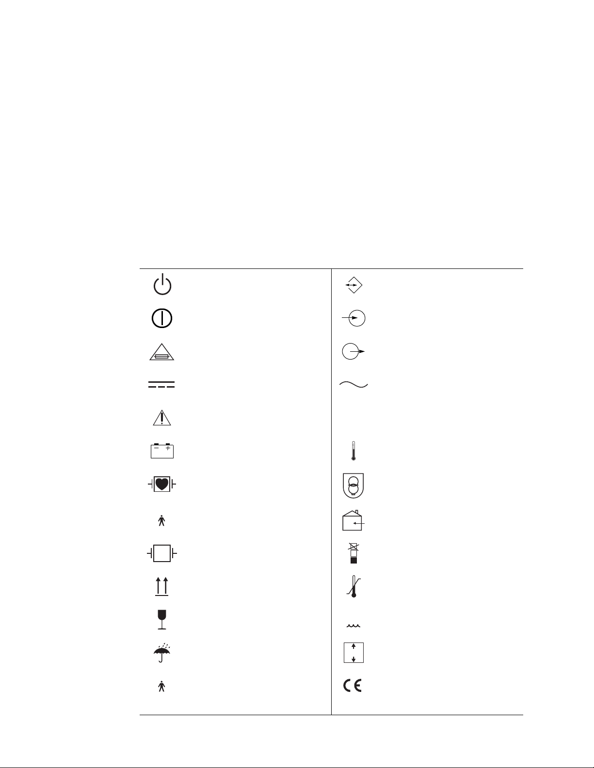
Symbols
The following symbols appear in the monitor documentation and on monitor labels. These
internationally recognized symbols are defined by the International Electrotechnical
Commission, IEC 878 and IEC 417A.
Off (Standby) Two-way communication port
On Input port to monitor
For continued fire protection, use only the
specified fuse.
Direct current Alternating current
Caution: Refer to Reference Guide and
accompanying documentation.
Battery charging when green indicator
illuminated.
All patient connections are Type CF, isolated
for direct cardiac application, and protected
against defibrillation.
All patient connections are Type BF, and
protected against defibrillation.
Protected during defibrillation Stacking limit by number
This way up Temperature limits
Fragile Humidity limit
IPX1
Signal output port from monitor
Enclosure Protection Drip proof:
Classification IPX1 per IEC Publication 529.
Temperature sensor input
Transformer meets requirements of a shortcircuit-proof safety-isolating power
transformer.
For indoor use only (on power adapter only).
n
a
n%
Keep away from rain Altitude limit
All patient connections are Type B The CE mark signifies the device has met all
n
essential requirements of European Medical
Device Directive 93/42/EEC for a Class 1
1
product.
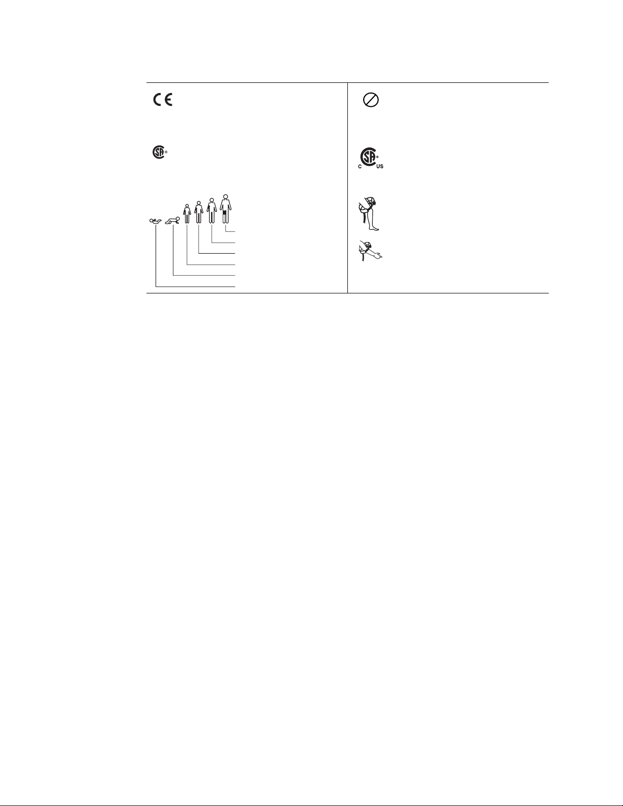
4 Safety Summary Welch Allyn Propaq Encore Vital Signs Monitor
The CE mark and notified body registration
number signify Propaq CS Series monitors
0123
have met all essential requirements of
European medical device directives 93/42/
EEC.
The Canadian Standards Association has
NRTL/C
Evaluated to CSA 601-1
and UL2601-1
evaluated this device according to CSA 6011 and Underwriters Laboratory Standard UL
1
2601-1.
NIBP cuff sizes:
Thigh
Large adult
Adult
Small adult
Child
Infant
a. This symbol is on the Universal Power Adapter.
Single-use only (not reusable).
2
This device has been tested and certified by
the Canadian Standards Association
International to comply with applicable U.S.
and Canadian medical safety standards.
Apply the NIBP cuff as shown.

5
2
Overview
Purpose and Scope
The Propaq Encore Service Manual is intended as a reference for monitor maintenance
and repair to the field replaceable unit (FRU) level (“Field Replaceable Units (FRUs)” on
page 117). This manual provides the technically qualified service person with
troubleshooting information, repair procedures, and calibration and performance
verification instructions. A technical overview of the monitor subsystems is provided as an
introduction to the device’s circuitry and pneumatics.
Note
This manual is intended for the technically qualified service person. Service training
classes on Welch Allyn’ products are available. Contact Welch Allyn Technical Service for
information.
Configurations vary nationally. Some early versions of the Propaq Encore do not
include impedance pneumagraphy (RESP) in some countries.
Other Applicable Documents
Several other documents are available for the Encore monitor. Refer to those documents
for other than maintenance and repair information. Check the Encore Reference Guide for
information on other user’s documentation.
Title Part Number
Propaq Encore Reference Guide, English 810-0640-XX
Products & Accessories Guide 810-0409-XX
Unpacking Procedure
Use the following guidelines when unpacking the Encore monitor from its shipping
carton.
1. Before opening the Encore monitor shipping carton, check it for damage.
2. If damage is apparent, stop unpacking the carton and contact the shipping company
for further instructions. If the carton is intact, unpack the Encore monitor.
3. With the Encore monitor out of its carton, check to see that all the items listed on the
packing slip (provided with shipment) are in the shipping carton.
4. If an item is missing, first recheck the carton, then check with your receiving
department. If necessary, contact Welch Allyn at the address and phone number
shown below.

6 Overview Welch Allyn Propaq Encore Vital Signs Monitor
Note
Save the shipping carton and packing material for repacking the Encore monitor in
case it needs to be sent to a repair center or back to Welch Allyn for service.
Warranty Service
DO NOT ATTEMPT TO REPAIR the Encore monitor yourself during the warranty period.
For service and repair, contact Welch Allyn as described below.
Technical Support Services
Welch Allyn offers a wide range of technical support services including:
• 24-hour telephone support
• loaner equipment
• service contracts
• field replaceable units (FRUs)
• factory repair
For any of these services, contact Welch Allyn Technical Support at the following
numbers:
USA 1-800-535-6663 France (+33) 1-60-09-33-66 Australia (+61) 2-9638-3000
Latin America (+1) 305-669-9591 Germany (+49) 7477-927-173 Singapore (+65) 6291-0882
European Call Center (+353) 469-067-790 Canada 1-800-561-8797 Japan (+81) 3-5212-7391
United Kingdom 0-207-365-6780 South Africa (+27) 11-777-7509 China (+86) 21-6327-9631
Worldwide Internet Access
World Wide Web (WWW) URL: http://www.monitoring.welchallyn.com/service
World Wide E-mail: solutions@monitoring.welchallyn.com
Recommended Service Intervals
At the intervals listed below, check the Encore monitor for normal operation.
Interval/Condition Perform Located in this manual
Every 6 months to 2 years
(according to hospital protocols).
If battery does not retain a charge. Check battery pack capacity. “Troubleshooting”
Monitor is dropped or suspected of
damage or rough handling.
Suspected malfunction with all or
part of monitoring parameters.
Complete risk (leakage) current Safety Check
followed by a Functional Verification.
Complete Safety Check followed by Functional
Verification.
Functional Verification of suspected parameter(s). “Functional Verification”
“Functional Verification”
“Functional Verification”
Monitor does not pass Functional
Verification.
Calibration of monitoring parameter circuits, or
repair, followed by Safety Check and Functional
Verification.
“Functional Verification”
and “Calibration”

Service Manual Overview 7
WARNING If the monitor is opened for repair or calibration, a dielectric strength
test must be completed to ensure the integrity of the patient isolation barrier. The
dielectric strength test procedure is provided in “Functional Verification” on
page 11.
Identifying Propaq Encore Configurations
The following table identifies Propaq monitor configurations and how they are indicated.
The model-option number and serial number are located on the back of the housing. The
monitor indicators are located under the handle on the back.
Table 1. Monitor Configurations
Product Model Option Parameters
Propaq Encore Monitor 202-EL ECG, NIBP, Two Temps, Resp, EL Display
204-EL ECG, NIBP, Two Temps, IBP, Resp, EL Display
206-EL ECG, NIBP, Two Temps, 2 IBP, Resp, EL Display
SpO2-Only Module 210 SpO2 and one of the following:
Nellcor MP-405 (Top level assembly 007-0059-XX)
Nellcor MP-203 (Top level assembly 007-0020-XX)
Nellcor MP-507 (Top level assembly 007-0109-XX)
Masimo MS3 (Top level assembly 007-0060-XX)
Expansion Module (See next table.)
a
a. The Acuity option is available with all models.)

8 Overview Welch Allyn Propaq Encore Vital Signs Monitor
Table 2. Expansion Module Option Configurations
Option
Number
Printer Mainstream CO2Sidestream CO2SpO
2
Top Level Assembly
Number
221 Yes No No N/A 007-0046-XX
222 No No No Nellcor MP-203 007-0050-XX
223 Yes No No Nellcor MP-203 007-0047-XX
223 Yes No No Nellcor MP-203 007-0051-XX
223 Yes No No Masimo MS3 007-0069-XX
223 Yes No No Nellcor MP-405 007-0086-XX
223 Yes No No Nellcor MP-507 007-0116-XX
224 No Yes No Nellcor MP-203 007-0049-XX
224 No Yes No Masimo MS3 007-0070-XX
224 No Yes No Nellcor MP-405 007-0085-XX
224 No Yes No Nellcor MP-507 007-0115-XX
225 Yes Yes No Nellcor MP-203 007-0048-XX
225 Yes Yes No Masimo MS3 007-0071-XX
225 Yes Yes No Nellcor MP-405 007-0084-XX
225 Yes Yes No Nellcor MP-507 007-0114-XX
226 No No Yes Nellcor MP-203 007-0045-XX
226 No No Yes Masimo MS3 007-0072-XX
226 No No Yes Nellcor MP-405 007-0083-XX
226 No No Yes Nellcor MP-507 007-0113-XX
227 Yes No Yes Nellcor MP-203 007-0043-XX
227 Yes No Yes Masimo MS3 007-0073-XX
227 Yes No Yes Nellcor MP-405 007-0082-XX
227 Yes No Yes Nellcor MP-507 007-0112-XX
228 No Yes Yes Nellcor MP-203 007-0052-XX
228 No Yes Yes Masimo MS3 007-0074-XX
228 No Yes Yes Nellcor MP-405 007-0081-XX
228 No Yes Yes Nellcor MP-507 007-0111-XX
229 Yes Yes Yes Nellcor MP-203 007-0044-XX
229 Yes Yes Yes Masimo MS3 007-0075-XX
229 Yes Yes Yes Nellcor MP-405 007-0080-XX
229 Yes Yes Yes Nellcor MP-507 007-0110-XX

Service Manual Overview 9
Self Test and Service Menus
The Encore monitor includes built-in self-tests that verify the integrity of its hardware and
software each time you turn it on. If the monitor turns on and displays the Main Menu, all
self-tests were passed. If a self-test results in a failure, a message and error code are
displayed indicating the failure mode. Refer to “Troubleshooting” on page 43 and contact
Welch Allyn Technical Support for help.
The Encore monitor contains software routines that make the Functional Verification and
Calibration procedures quicker and easier. You access these routines through the Service
Menus as indicated in each of the procedures.
The figure below shows the hierarchy of the Service Menus once you enter the top level
Service Menu.
The procedures in this manual indicate which buttons to push by separating each button
menu name with the (>) character. For example, to access the Service Menu, the
procedures would indicate for you to press SETUP > MORE > MORE > SERVICE > YES,
which means you press the SETUP button, then the MORE button, then the MORE
button, then the SERVICE button, and finally the YES button.
Note
service menus
The figure illustrates all Service Menu functions. Some of these functions are not
available if you do not have the appropriate option.
NIBP TEST IBP TEST SpO2 TST CO2 TEST MORE
PUMP TEST AUTO PMP NIBP CAL ZERO PREV MENU
TEMP TEST PIXL TEST NET TST MORE
CYCLE CHECKER 1 CHECKER 2 BORDER PREV MENU
LOOP TEST OUT TEST PREV MENU
MAIN CAL MAIN TEST SIDE CAL SIDE TEST
PREV MENU
SETTINGS KEY TEST SYSTEM
(Software v. 2.5X only)
KEY 0 KEY 1 KEY 2 KEY 3
NEXT CHANGE ALL ALARM
MORE
PREV MENU
PREV MENU

10 Overview Welch Allyn Propaq Encore Vital Signs Monitor

11
3
Functional Verification
Introduction
The functional verification procedures ensure proper operation of the Encore monitor and
its options. These procedures should be performed following module-level repairs,
calibration, or whenever there is a question about the accuracy or safety of the patient
functions.
Use the calibration procedures (“Calibration” on page 33) to return the monitor to
operation within its performance specifications. If the monitor does not pass the
functional verification, or when it is time to do a routine calibration, see “Calibration” on
page 33.
The Encore’s service menu facilitates the functional verification. It has several features for
testing and verifying the NIBP (cuff) channel, display, invasive pressure channel, and
printer. Refer to “Over v iew ” on page 5 for information about the Service Menu.
WARNING Whenever the monitor is opened for calibration or repair, a risk
(leakage) current safety check as well as a dielectric strength integrity (hi-pot) test
must be performed as described in this section.
Self Tests
Many functions, such as alarms, waveform and scale sizing, and printer control, are
software operations. During the monitor’s power-up self-test, the integrity of all
programming is checked first. If software testing is successful, hardware tests are
initiated. If all testing is successful, the monitor is ready for use. (See “Troubleshooting”
on page 43 for information on error messages.)

12 Functional Verification Welch Allyn Propaq Encore Vital Signs Monitor
Required Equipment
You will need the following equipment to verify that all functions of the Encore operate
correctly. All test equipment must be calibrated to function within parameters specified
by the manufacturer, and must be traceable to a national calibration standard.
Some equipment can be manufactured. See “Manufacturable Test Equipment” on
page 123 for information on manufacturable test equipment.
Table 3. Required Equipment
Description
Luer connector, male, for use with 1/8" I.D. tubing (Value Plastics, MTLL230-1)
Luer connector, female, for use with 1/8" I.D. tubing (Value Plastics, FTLL230-1)
Test water trap, Welch Allyn, 008-0370-00
1/8" inside diameter tubing
Flow meter, Cole Parmer E 32000-06, 200ml/min. or equivalent
0 to 300 mmHg calibrated digital pressure meter, with inflation squeeze bulb (Netech, Digamano, or equivalent)
50 MHz triggered sweep oscilloscope
Variable dc power supply, 0-28 V, 3A with voltage and current metering
Dynatech/Nevada 213A, 214A, 215A, or 217A with IBP, Temperature, and EGG Cable/Leads
Adult cuff (provided with monitor); Neonatal cuff #3; 3 cm diameter solid cylinder; solid cylindrical object about the size
of an adult’s arm
Welch Allyn cuff calibration kit, Welch Allyn PN 008-0012-XX
Power supply adapter cable, Welch Allyn PN 008-0290-00
Physio Control LifePak 5 or LifePak 6s with appropriate Welch Allyn Defib Sync adapter to use as Defib Sync Marker
pulse source
Propaq ac power adapter (provided with the Encore)
Safety analyzer, Dynatech/Nevada, 431F-1D or equivalent
Rod-L Model M100AVS5 high-voltage potential (hi-pot) tester, or equivalent
Static-free work area
Simulator, Fluke (Biotek) Index 2 XL/XLFE
SpO
2
Test gas source: dry 4% to 10% CO
concentration must be certified to ±0.01. (Convert percentage to partial pressure (mmHg) as instructed in “Partial
pressure of test gas source” on page 27.)
Two rubber test tube stoppers, with 1/8" to 1/4" holes drilled through (for CO2 tests)
a. Of the gas tolerance available, usually described as ±0.03% absolute, the container must contain at least 2,000 psi grams of gas, to
be within ±0.01% of the certified percentage of gas stated on the tag supplied by the vendor. The acutal percentage of gas in the
container may vary from lot to lot.
, balance air (with flow meter). Gas may be between 4% and 10%, but exact CO2
2
a
Safety Tests
The following two safety tests, a risk (leakage) current safety check and a dielectric
strength integrity (hi-pot) test, must be performed whenever the Encore has been opened
for calibration or repair.

Service Manual Functional Verification 13
Note
A hi-pot test is only required if the monitor has been opened.
Risk (Leakage) Current Test
A risk (leakage) current test must be performed to verify that the patient remains
electrically isolated from the power circuits of the Encore.
Check leakage currents using a Dynatech/Nevada 431F-1D safety analyzer or its
equivalent. The source current should not exceed 10μA rms. The sink current, measured
between the isolated patient connections (ECG) and the dc power input connector of the
monitor, should not exceed 20μA rms. See the analyzer's operator's manual for the
proper safety check procedure.
Note
Table 4. Electrical Connections for Patient Risk (Leakage) Current Safety Tests
Safety Test Power Adapter Monitor
Source current Plugged into analyzer
Sink current Not used Connected to ground
Because of the all-insulated construction of the monitor, an Enclosure Leakage
Current Test to ground is not necessary.
outlet
dc Input
Connected to power
adapter
connector on analyzer
Monitor
Cable
RA
LA
LL
C
RL
RA
LA
LL
C
RL
Safety
Analyzer
RA
LA
LL
C
RL
RA
LA
LL
C
RL
Dielectric Strength (Hi-Pot) Test
Because of the close spacings of the monitor's internal components and the critical
positioning of the insulation sheet within the monitor, Welch Allyn recommends that a
dielectric strength test be performed following any procedure in which the monitor is
opened.
WARNING The Hi-Pot test is extremely hazardous. Only qualified service
personnel should perform this test. Conduct the test only on an insulated table
top, away from other people and equipment.
Use a Rod-L Model M100AVS5 high-voltage potential tester, or equivalent. Refer to the
Rod-L instruction manual for operating information and safety recommendations.
1. Set the high voltage potential of the tester as specified in the table below.

14 Functional Verification Welch Allyn Propaq Encore Vital Signs Monitor
Table 5. Summary of Connection Points and High-Voltage Test Potentials
Tester's high-voltage terminal
connection
All ECG leads on patient cable
connected together
2. Connect the high-voltage output lead of the tester to all ECG leads, using a dedicated
patient cable reserved for use only in such tests.
3. Connect the tester's chassis-connected return lead to the monitor's dc input
connector, using a suitable plug.
4. Apply the test voltage for one second. The tester must not indicate dielectric
breakdown.
WARNING If any dielectric breakdown occurs, do not use the monitor. All
internal sheet insulation barriers must be properly installed. Check the monitor to
determine the cause of dielectric breakdown; then repair the monitor or return
the monitor to Welch Allyn for repair.
Functional Verification
The functional verification must be done only when the monitor is fully assembled. If the
monitor has been stored for longer than one month without the monitor connected to the
ac adapter (for recharging), the battery voltage must be checked. The battery must be
replaced if it cannot hold a charge. Refer to “Battery Capacity Check” on page 45.
Tester's grounded return
connection
DC input connector; all pins connected
together
High-voltage test parameters
Output: 4000 V ac rms
Current Limit: 2.5mA
Ramp-up: 8 seconds
Dwell: 1 second
Note
Power System
The following steps check the integrity of the Encore’s power system.
1. Turn the ac power adapter’s power switch off.
2. Plug the ac power adapter into an ac mains receptacle and connect it to the Encore’s
3. Check that the green LED charging indicator on the monitor’s right side panel is off.
Some configurations of the Encore monitor do not include impedance
pneumography (RESP) and other neonatal monitoring parameters. In these
versions, RESP does not appear in menus or on the screen displays. You can
ignore RESP and other terms relating to neonatal monitoring when indicated in
the following instructions.
If you plan to use a Dynatech/Nevada model 213A, 215A, or 217A Patient
Simulator to simultaneously simulate ECG and invasive blood pressure, see
“Dynatech/Nevada Patient Simulator Modification” on page 125 for important
information.
Before starting the verification procedures, charge the battery for at least 8 hours
with the monitor turned off. (Charge for 12 hours if a Printer or SpO
module is
2
attached.)
right side panel dc power connector.

Service Manual Functional Verification 15
4. Turn on the power adapter’s power switch.
5. Check that the green LED on the power adapter turns on and that the green LED
charging indicator on the monitor’s right side panel turns on.
6. Disconnect the power adapter from the monitor. Check that the monitor’s green LED
charging indicator on the right side panel turns off.
Caution In the next steps, carefully check for the proper polarity of the
connection between the power supply and the monitor. If voltage is applied with
the wrong polarity, it will open the right side panel fuse (F1). Refer to the figure
below to verify proper polarity.
7. Set the dc power supply meter to Volts and turn the power switch on; set it for
15.0V ± 0.1V.
8. Turn off the dc power supply.
9. Using the Welch Allyn dc power supply adapter cable, refer to the figure below for
polarity and connect the dc power supply to the monitor's dc input connector on the
right side panel.
RIBBED (+) SMOOTH (-)
0696-02
10. Turn on the dc power supply.
11. Check that the green LED indicator lights up.
Note
Initial charge current for a low battery is higher than for a charged battery. As the
battery charges, the current will decrease. The current draw may slowly drop the
longer the dc supply is connected to the monitor.
12. Switch the dc power supply meter to current and check that the current draw from
the supply is less than 1.8 A.

16 Functional Verification Welch Allyn Propaq Encore Vital Signs Monitor
13. Vary the power supply from 12 V to 28 V and verify that the charging LED stays on.
14. Turn off the power supply.
15. Disconnect the supply from the monitor.
System Tests
The following procedures check that the buttons operate properly, that the display works
correctly, and that the date is correctly displayed.
1. Turn on the monitor.
2. Verify that no error messages appear and the monitor correctly powers up.
3. Press SETUP > MORE > MORE > SERVICE > YES > MORE > PIXL TST to test the
display.
4. Press CYCLE three times, each time verifying that no pixels are missing.
5. Press MAIN MENU twice.
6. Press SETUP > WAVE SEL > INSERV to access the inservice features. This generates
simulated waveforms.
7. If dual stream monitor, look for CO2 Sensor Change - Switching to Mainstream, YES
or NO.
8. IBP screen indicates need to zero P1 or P2.
9. Press MAIN MENU.
10. Using the appropriate table below as a guide, press the indicated buttons in sequence
and verify that the monitor responds as indicated and that the buttons do not stick.
Sequence for Software Versions 2.5
X
Press Result
FREEZE/UNFREEZE Freezes the waveforms
FREEZE/UNFREEZE Unfreezes the waveforms
SETUP Changes the menu
ALARMS Changes the display to ALARM STATUS
4 SUSPND (on menu) 4 SUSPND changes to RESUME
ALARM SILENCE/RESUME (button) Changes RESUME to 4 SUSPND
LIMITS Changes display to HR Limits
NEXT Moves cursor block: Next block within selected parameter limits, NEXT
MAIN MENU (button) Returns to the main menu
PAGE moves to next parameter
NIBP START/STOP (button) Starts the NIBP pump
NIBP START/STOP (button) Stops the NIBP pump

Service Manual Functional Verification 17
Sequence for All Other Software Versions
Press Result
FREEZE/UNFREEZE Freezes the waveforms
FREEZE/UNFREEZE Unfreezes the waveforms
SETUP Changes the menu
ALARMS Changes the display to ALARM STATUS
SUSPEND (on menu) SUSPEND changes to RESUME
ALARM SUSPEND/RESUME (button) Changes RESUME to SUSPEND
ALL ALRM Changes display: Turn All Off, Are You Sure, Y or N
LIMITS Changes display to HR Limits
NEXT Moves cursor block: Next block within selected parameter limits, NEXT
PAGE to next parameter
MAIN MENU (button) Returns to the main menu
NIBP START/STOP (button) Starts the NIBP pump
NIBP START/STOP (button) Stops the NIBP pump
1. Press ECG/RESP > MORE. Then press CHANGE to select the four HR/PR TONE
levels. Verify that the tone volume changes and goes off when turned OFF. Set the
volume to LOW.
2. Press MAIN MENU.
3. Software versions 2.5X: Press SETUP > MORE > MORE > SERVICE > YES > MORE
> MORE > SETTINGS > ALL ALRM. Verify alarm status displays "TURNING OFF ALL
AUDIBLE VITAL SIGNS ALARMS", "ARE YOU SURE?", YES or NO. Then press MAIN
MENU.
4. All software versions: Press SETUP > MORE > MORE (> TIME/DAY for monitor
software less than version 2.0) and check that the displayed time and date are correct.
If incorrect, press NEXT and UP or DOWN to select and change the time and date,
and then set by pressing the ENTER button.
5. Turn off the monitor.
ECG/RESP Channel and Alarm Indicators
The following procedures verify the ECG channel and the alarm indicator drivers. The
setup procedure below is used for both the visual and the electrical checks that follow.
Setup
1. Turn on the monitor and verify that it powers up correctly.
2. Put the monitor into FACTORY ADULT MODE.
Software version 2.XX: SETUP > MORE > CHANGE > SETUP > USE NOW > YES
Software version 1.XX: SETUP > MORE > CHANGE > ADULT > YES > MORE >
PROGRAM > DEFAULT > YES
3. Press MAIN MENU.

18 Functional Verification Welch Allyn Propaq Encore Vital Signs Monitor
4. Set the patient simulator as follows:
• ECG Waveform: normal sinus rhythm
• ECG Rate: 80 beats per minute (bpm)
• ECG Size: 1 mV amplitude
• Resp Lead: Lead I
• Resp Baseline Impedance: 1 KΩ
• Resp Rate: 40 breaths/minute (br/m)
• Resp Breath Amplitude: 1.0Ω
5. Set the monitor as follows:
• Respiration Lead: Lead I (ECG/RESP > MORE; select lead and change as
necessary)
• ECG Lead: Lead II (ECG/RESP > ECG LEAD)
• ECG Size: 1 mV (ECG/RESP > ECG SIZE)
• Resp Size: 8X (ECG/RESP > RESP SZE)
• Respiration ON (ECG/RESP > MORE; select and set RESP to ON)
• ECG Sweep: 25 mm/Sec (SETUP > MORE; select and change HR/PR sweep as
necessary)
•Alarms (software versions 2.5X): Set alarm limits to OFF for HR/PR and RR/BR
(SETUP > ALARMS > LIMITS > ON/OFF > NEXT > ON/OFF > NEXT PAGE > ON/
OFF > NEXT > ON/OFF. Press the MAIN MENU button. The ALARM(S) OFF light
will turn on, indicating one or more alarm limits have been disabled.
•Alarms (all other software versions): All alarms OFF (SETUP > ALARMS > ALL
ALRM [software version 2.XX: press YES when prompted] until all alarms are off
except for the Apnea alarm, which cannot be turned off. The ALARM(S) OFF light
will turn on, indicating that one or more alarm limits have been disabled.
• Audible vital signs alarms (software versions 2.5X): OFF (SETUP > MORE >
MORE > SERVICE > YES > MORE > MORE > SETTINGS > ALL ALRM > YES.
The ALARM light will turn on, indicating the patient alarms are suspended.
6. Connect the ECG channel to the patient simulator using all five ECG leads.
Part 1— Visual Check
1. Press MAIN MENU.
2. Press the FREEZE/UNFREEZE button to freeze the waveform.
3. Check that a normal sinus rhythm ECG waveform is displayed with a peak-to-peak
amplitude of 10 ±1 mm. There should be a soft beep tone with each QRS event.
4. Check that the monitor’s displayed respiration peak-to-peak amplitude is 12.5 ±1 mm.
5. Press FREEZE/UNFREEZE to unfreeze the display.
6. Check that the monitor's heart rate display is 80 ± 4 bpm, and the respiration rate is
40 ± 2 bpm before proceeding to the next step.
7. Disconnect the LA ECG lead wire from the simulator.

Service Manual Functional Verification 19
8. Check that an equipment alarm occurs. The EQUIPMENT ALERT / MULTIPLE
message should accurately indicate the removed lead. The ALARM(S) OFF light will
flash.
• Software version 2.5X: The ECG FAULT will flash in the upper left-hand corner of
the screen.
• All other software versions: The ECG FAULT and RESP FAULT will alternate in the
upper left-hand corner.
9. Press any button to acknowledge. Check that the ALARM(S) OFF light is on and no
longer flashing.
10. Disconnect the LL ECG lead from the simulator.
11. Check that an equipment alert occurs. The ECG FAULT and RESP FAULT will alternate
in the upper left-hand corner. The ALARM(S) OFF light will flash.
• Software version 2.5X: The EQUIPMENT ALERT - MULTIPLE message should be
displayed.
• All other software versions: The EQUIPMENT ALERT / ECG FAULT / MULTIPLE
LEAD FAIL message is displayed.
12. Press any button to acknowledge. Check that the ALARM(S) OFF light is on and no
longer flashing.
13. Reconnect the LL ECG lead, and then LA ECG lead.
14. Check that the ALARM(S) OFF light is on. Software version 2.5X: Check that the
ALARM light is on.
15. Check that the monitor's heart rate display is 80 ± 4 bpm, and the respiration rate is
40 ± 2 bpm before proceeding to the next step.
16. Software version 2.5X: Press RESUME to enable alert and alarm tones.
All other software versions: Press SETUP > ALARMS > ALL ALRM to turn all alarms
ON.
17. Press SETUP > ALARMS > STAT SET to automatically set heart and respiration rate
alarm limits. Software version 2.XX: Select YES when prompted.
18. Check that the ALARM(S) OFF light is off.
19. Check that the ALARM light is off.
20. Set the patient simulator heart rate to 180 bpm or higher.
21. Check that an alarm violation occurs, causing the tone to sound and the ALARM light
to flash.
22. Software version 2.5X: Press the 4 SUSPND button and verify that the tone turns off
and the ALARM light is on and no longer flashing.
Software version 2.XX: Press the ALARM SUSPEND/RESUME button and verify that
the tone turns off and the ALARM light is on and no longer flashing.
23. Press MAIN MENU.
24. Set the patient simulator heart rate to 80 bpm.
25. Check that the ALARM light is ON.
26. Press SETUP > ALARMS > RESUME.

20 Functional Verification Welch Allyn Propaq Encore Vital Signs Monitor
27. Check that the ALARM light is OFF.
28. Press MAIN MENU.
Part 2— Electrical Check
Use the same setup for this check described in “Setup” on page 17.
1. Set the patient simulator to provide pacer signals.
2. If the pacer indicator is not on, press ECG/RESP > MORE and select and change the
pacer setting.
3. Check that a dashed vertical line is displayed on the ECG waveform each time a pacer
pulse occurs.
4. Set the oscilloscope to 0.2 second/division sweep and 0.5 Volt/division amplitude.
5. Insert a short piece of thin conductive wire into each of the ECG X1000 connector
holes shown in the figure below or use real time ECG Out cable 008-0320-00.
ECG X1000
GND
(scope gnd. clip)
ECG
(scope probe)
0696-69
6. Connect the scope probe and the scope ground clip to the wires.
7. Check that the scope displays an ECG signal with an amplitude of 1 V ±100 mV
baseline to peak of R-wave.
Note
Some amount of mains noise may also be present in the signal.
8. Move the wire and scope probe from the ECG pin of the ECG X1000 connector to the
DEFIB SYNC connector pin shown in the figure below or use Defib Sunc Output
cable, 008-0237-00. Leave the scope’s ground clip where it is.
DEFIB SYNC
SYNC OUT
(scope probe)
0696-70
9. Change the vertical sensitivity of the scope to 1 Volt/division.
10. Check that the scope displays a 5 V p-p pulse with a 100 ±5 ms width.

Service Manual Functional Verification 21
11. Disconnect the scope probe and ground clip and remove the wires from the
connectors.
12. Using either a LifePak 5 or LifePak 6s and appropriate Welch Allyn adapter, set up the
monitor and defibrillator according to instructions provided in the Defib Sync User’s
Guide.
13. Check the monitor display for sync markers on the ECG waveform.
14. Disconnect the defibrillator from the monitor.
IBP
Note
15. Disconnect the ECG cable from the monitor. (Disconnecting an active channel
The following procedure verifies the operation of the invasive blood pressure channels.
Some models of the Propaq Encore have no IBP channels; skip this procedure if your
Encore does not support IBP. If your Encore has multiple IBP channels, repeat the
verification procedure for each channel.
Note
If the patient simulator does not also provide an appropriate ECG signal, the heart
rate value will be displayed as – – – and an alarm violation will occur.
initiates an equipment alarm; press any key to acknowledge the discontinuance of
ECG monitoring.)
Caution Many blood pressure simulators are not intended to be used as
calibration standards. Use only the blood pressure simulators specified in
“Required Equipment” on page 12.
If you are using the Dynatech/Nevada model 213A, 215A, or 217A patient
simulator, do not simultaneously monitor ECG and invasive blood pressure (IBP)
unless the modification to the simulator is performed as described in “Dynatech/
Nevada Patient Simulator Modification” on page 125. If you do not wish to modify
your simulator, use ECG and IBP independently.
1. Press SETUP > WAVESEL and check that the P1 and P2 waveforms are turned on.
2. Connect the IBP cable from the patient simulator to an IBP input jack on the left side
panel of the Encore.
3. Set the simulator output pressure to 0 mmHg.
Note
4. Zero P1 by pressing ZERO P1.
5. Check that ZEROED is displayed.
6. Press RESCALE.
7. Check for a noise level of ≤3 mm on the IBP waveform.
8. After allowing a few seconds for settling, check that the mean pressure reading is 0
9. Set the pressure simulator to 200 mmHg.
If an alarm tone sounds, press the SUSPEND/RESUME button.
mmHg ±1 mmHg.

22 Functional Verification Welch Allyn Propaq Encore Vital Signs Monitor
10. After allowing a few seconds for settling, check that the mean pressure reading is 200
mmHg ±2 mmHg.
11. Remove the cable from the P1 input jack and verify that the message: P1 FAULT TRANSDUCER NOT DETECTED appears.
12. Press any button to acknowledge the discontinuance of IBP monitoring.
13. Press MAIN MENU.
NIBP
1. Connect the cuff, digital pressure meter, bulb, and the Encore together with the cuff
calibration kit. Using T-connectors from the kit, connect the cuff, pressure meter, and
bulb.
2. Connect this NIBP test setup to the pressure transducer at PT1 on the Analog board.
3. Wrap the adult cuff around the black tube volume or a cylindrical object about the size
of an adult’s arm.
4. Press SETUP > MORE > MORE > SERVICE > YES > NIBP TEST > NIBP CAL.
Note
The NIBP CAL mode holds pressure for 10 minutes. If performing steps 4 through
9 takes longer than 10 minutes, press NIBP CAL again.
5. Close the valve on the bulb and inflate the cuff to 250 mmHg as shown on
thepressure meter.
6. Check that the readings (PR1 and PR2) on the monitor's display are 250 ±3 mmHg
(PR1) and 250 ±15 mmHg (PR2), as show in the figure below.
19:00:25
NIBP TEST BATTERY: 8.1 VOLTS
CNTS mmHg DAC VALVE
PR1: 578 249.4 130 0
PR2: 338 259
OSC: 1600
LEAK: 10 mmHg DIAG: 0
BLEED: mmHg/min PUMP: secs
PUMP TEST
AUTO PMP NIBP CAL ZERO PREV MENU
7. Manually reduce the pressure as indicated on the pressure meter to each of the levels
shown in the following table, and check the displayed value of PR1 to be within the
tolerance listed in the following table.
Pressure (mmHg) Tolerance
(mmHg)
270 ± 4
250
± 3

Service Manual Functional Verification 23
Pressure (mmHg) Tolerance
(mmHg)
200 ± 2
100
50
20
8. Reduce the pressure to 0 mmHg and check that the displayed readings (PR1 and PR2)
are 0 ± 2 mmHg.
9. Close the bulb valve.
10. Press CANCEL. (If there is no CANCEL button at this time, go to the next step.)
11. Disconnect the adult cuff from the test setup and connect the neonatal cuff #3 that is
wrapped around a solid 3 cm diameter cylinder, the black PVC tube volume.
12. Press PUMP TEST.
13. Check that the pump inflates the cuff to approximately 280 mmHg.
14. After four minutes, check that the displayed leakage is less than 50 mmHg.
Note
15. Press MAIN MENU.
16. Disconnect the cuff and Cuff Calibration Kit.
If the leakage exceeds this specification, first check all exterior hoses and fittings
before diagnosing an internal air leak problem.
± 2
± 2
± 2
Temperature
1. Plug a 37.0° C YSI 400 series (two conductor) calibrated temperature probe simulator
into the T1 jack on the Encore’s left side panel.
2. Check that the T1 temperature is 37° ± 0.1° C.
3. Repeat Steps 1 and 2 for T2.
4. Plug a 37° C YSI 700 series (three conductor) temperature probe simulator into the T1
jack.
5. Check for 37° ± 0.1° C.
6. Repeat Steps 4 and 5 for T2.
7. Remove all connectors and turn the Encore off.
Functional Verification for Masimo SpO
This functional verification procedure helps to confirm the proper operation of the Masimo
Pulse Oximetry option installed in the Propaq monitor. This procedure supports the
requirements of routine preventive maintenance. No monitor disassembly is required to
perform this procedure.
You will need the following equipment to perform this procedure.
2
• Masimo-compatible SpO
cable.
2

24 Functional Verification Welch Allyn Propaq Encore Vital Signs Monitor
• Compatible adult SpO2 sensor for finger.
• BIO-TEK Index 2 Series SpO
Simulator with optical finger for sensor connection
2
(or equivalent).
1. Turn on power to the SpO
2. Connect the SpO
3. Apply the SpO
cable to the monitor and the SpO2 sensor.
2
sensor to the SpO2 simulator optical finger.
2
simulator.
2
4. Set the simulator manufacturer type (“MAKE”) to Masimo.
5. Set the simulator output to SpO
saturation 94% and pulse rate 60 beats per minute
2
(with no motion artifact selected).
Confirm that the monitor displays SpO
moving.
Confirm that the displayed saturation is 94% ±4 counts, and the displayed pulse rate
is 60 ± 4 bpm.
6. Disconnect the sensor from the simulator and cable, and disconnect the SpO
Functional Verification for Nellcor SpO
This functional verification procedure helps to confirm the proper operation of the Nellcor
Pulse Oximetry option installed in the Propaq monitor. This procedure supports the
requirements of routine preventive maintenance. No monitor disassembly is required to
perform this procedure.
You will need the following equipment to perform this procedure.
data and the pulse amplitude indicator is
2
2
cable.
2
• Nellcor-compatible adult SpO
• BIO-TEK Index 2 Series SpO
finger sensor
2
Simulator with optical finger for sensor connection
2
(or equivalent).
1. Turn on power to the SpO
2. Connect the SpO
sensor to the monitor and apply to the SpO2 simulator optical
2
simulator.
2
finger.
3. Set the simulator manufacturer type (“MAKE”) to Nellcor.
4. Set the simulator output to SpO
saturation 94% and pulse rate 60 beats per minute
2
(with no motion artifact selected).
Confirm that the monitor displays SpO
data and the pulse amplitude indicator is
2
moving.
Confirm that the displayed saturation is 94% ±4 counts, and the displayed pulse rate
is 0 ± 4 bpm.
5. Disconnect the sensor from the simulator.
6. Check that an equipment alarm occurs.
7. Press any button to acknowledge the discontinuance of SpO
monitoring.
2
8. Press MAIN MENU.

Service Manual Functional Verification 25
Sensor Compatibility
Some sensors are not compatible with the particular Nellcor processing board installed in
the Propaq. To determine which pulse oximetry optional processing board is installed in
the Propaq, find the option number on the back label of the Propaq, then refer to the table
“Expansion Module Option Configurations” on page 8. The following table shows how to
identify compatible sensors for each Nellcor option:
Table 6. Sensor Compatibility
Sensor Description Connector Compatible With
Pins Notches Color MP-203 MP-405 MP-507
Single-ended 7 0 Varies Yes No No
Differential 7 1 Varies Yes Yes No
OxiMax 9 2 Purple Yes Yes Yes
OxiMax-Exclusive 8 2 White No No Yes
Printer Tests
The following steps check the functionality of the printer.
Note
1. Disconnect all cables from the monitor.
2. Turn the monitor OFF then ON.
3. Press SETUP > WAVE SEL > INSERV.
4. Press MAIN MENU.
5. Wait at least 8 seconds and then press the printer's SNAPSHOT button.
6. Check that the printer prints an approximately eight-inch strip of the simulated patient
7. Press the printer's START/STOP button. The printer should begin continuous printing.
8. Press the START/STOP button to stop printing.
9. Lay the Propaq Encore on its back.
10. Press the START/STOP button to start printing.
Functional verification should be performed on the monitor before beginning the
printer tests. The monitor must be functioning properly in order to perform printer
tests.
data. The paper should stop only after the entire waveform has been fed out of the
printer.
11. Completely open the paper door on the bottom of the Expansion Module.
12. Check that the printer stops printing, and that an equipment alarm and CHECK DOOR
message appear on the monitor screen.
13. Cut or tear the printer paper in the printer mechanism from the roll, leaving the strip of
paper in the printer mechanism.
14. Completely close the paper door.

26 Functional Verification Welch Allyn Propaq Encore Vital Signs Monitor
15. Press the START/STOP button.
16. After the printer runs out of paper, check that an equipment alarm and PAPER OUT
message appear on the monitor screen.
17. Open the printer door and reload the paper into the printer.
18. Close the paper door and set the monitor upright.
19. Simultaneously press the PRINT TRENDS and START/STOP buttons.
20. Check that a test printout similar to one shown in the figure below is printed.
test print
VER. 1.00.01
5B 4F B7
CO2 Verification Preparation
The mainstream and sidestream CO2 functional verification procedures require calculating
the local barometric pressure and partial pressure of the test gas (in mmHg) to compare
to Propaq Encore displayed values.
Local barometric pressure
The first step is to determine the local barometric pressure:
1. Determine local altitude above sea level.
For worldwide locations, obtain altitude from local geological maps (U.S.G.S. maps in
the United States) or other local references on the maps. Refer to the table titled:
Uncorrected Barometric Pressure as as Function of Altitude; use this table to
determine the local uncorrected pressure (LUP).
2. Determine ATIS reported pressure (inches or millimeters of Hg).
For U.S. locations, consult local telephone directories to obtain the Automated
Terminal Information Service (ATIS) number, typically listed under United States
Government Offices, Department of Transportation, Federal Aviation Administration,
and Air Traffic Control Towers.
Among various statistics reported is the “altimeter,” which is given in four integers.
The four digits represent the barometric pressure as referred to sea level, in units of
inches of mercury, with an assumed decimal point occurring between the second and
third numbers.
For worldwide locations, equivalent altimeter statistics, in millimeters of mercury,
may be obtained from local agencies.
Note
The difference in altitude between the calibration site and the ATIS site should not
be greater than 30 m or 100 ft.
3. Determine local barometric pressure using LUP and ATIS. Apply the ATIS and LUP
values to the following formula to calculate the local barometric pressure (mmHg):
Loading...