


2.6 INITIAL SETUP
Place the TM 262TM Auto TympTM on a stable counter or table where it
will subsequently be used, and near a properly grounded wall outlet.
Attach accessories to their appropriately-labled connectors on the rear
panel of the TM 262 (see Figure 2-9).
Locate the POWER switch on the rear panel of the TM 262 and move
the switch to the ON ( ) position. Note that the lamp (F1) on the front
panel is illuminated, indicating the TM 262 is receiving power. The
TM 262 symbol will then appear on the display along with a listing of
the revision number for the Tymp/Reflex and Audiometry (if purchased)
software. Next, the display will default to the Tymp/Reflex mode and
the probe’s green lamp will begin to blink, indicating that the TM 262 is
ready to begin a test. If both the green and yellow lamps are illuminated at the same time, either the probe is occluded or the tymp/
reflex software did not properly initialize. Simply move the power
switch to the OFF ( ) position, inspect the probe tip for any signs of
an occlusion, and reposition the power switch to ON ( ). If both green
and yellow lamps are still illuminated and you are certain that the
probe is not occluded, contact the Welch Allyn Technical Service
Department (see page 55). In the meantime, it is still possible to
select the Audiometry mode (if purchased).
Allow the instrument to warm-up for about five minutes before conducting a test. This allows the electronic circuits to stabilize prior to use.
If the storage temperature is lower than the room temperature, allow
some additional time for the instrument to reach room temperature.
Warning
The TM 262 is designed to be used with a hospital grade outlet. Injury to personnel or damage to equipment can result when a three-prong to two-prong
adapter is connected between the TM 262 power plug and an AC outlet or
extension cord. Additionally, those TM 262 Auto Tymps that are equipped with
power transformers use a specific transformer (8000-0260, 8000-0261 or 8000-
0262) which should not be interchanged with any other transformer or supply.
The TM 262 is a specifically-calibrated device and the periodic service and
adjustments which the instrument may require should be done only by an
authorized Welch Allyn service technician.
11
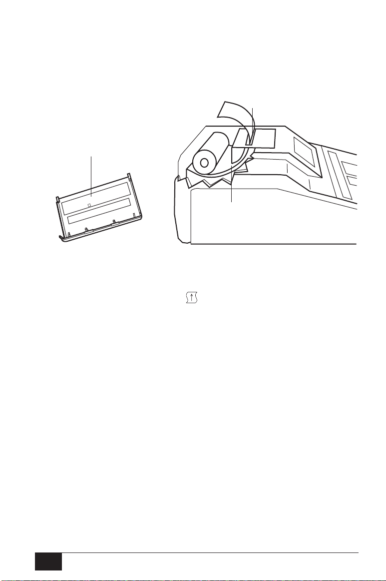
2.6.1 Loading The Paper
Remove the printer cover (see Fig. 2-3 for location) by placing your fingers along the back edge of the printer and pulling upward on the cover.
Cut the printer paper so that the leading edge of paper is straight across.
Place the roll of paper inside the paper well so that the paper will unroll
from the lower surface. See paper loading label for additional help
(Figure 2-11).
Paper exit
Paper loading
label
PAPER LOADING
INSERT THE LEADING EDGE SQUARELY INTO
THE PAPER ENTRANCE WHILE PRESSING THE
PAPER ADVANCE ON THE FRONT PANEL
FIGURE 2-11: Paper Loading
Position the leading edge of the paper roll into the paper entrance while
pressing the PAPER ADVANCE button. The paper will begin to appear out of the printer mechanism. Continue to advance the paper so
that a section of paper is long enough to pass through the printer cover
once it is repositioned over the printer.
Paper
entrance
2.6.2 Paper Storage
The TM 262TM Auto TympTM utilizes a thermal printer, which requires a
heat-sensitive paper to create an image. For maximum paper life, any
spare rolls of paper should be stored as follows:
1) Store in the dark, i.e., in a drawer or cabinet
2) Do not store above 77°F (25°C)
3) Store at less than 65% relative humidity
The above recommendations are for the maximum paper life (greater
than five years). Storing your TM 262 thermal paper at high temperatures
or high humidity levels will only shorten the total paper life.
12
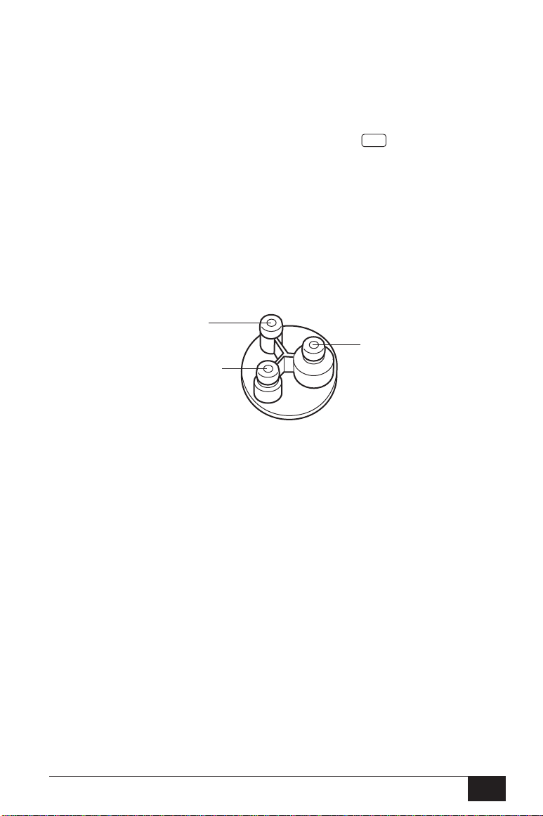
2.7 PRETEST TYMPANOMETRY CHECKS
For your convenience, a test cavity is provided with your TM 262
Auto TympTM. This test cavity enables you to quickly verify the proper
calibration of your unit. Welch Allyn, Inc. strongly recommends that
you make this quick check a part of your daily routine.
2.7.1 Calibration
To initiate the quick check, select the Tymp only mode and insert
the probe (without a tip on it) into the 0.5 cm3 opening on the test
cavity. See Figure 2-12.
NOTE
Since the TM 262 is designed to start automatically, it is important that the
probe is inserted as quickly and as smoothly as possible. During the calibration check, the probe must be held carefully and without movement. Do not
place the probe on the same counter as the instrument or any moving object
during this check, as mechanical noise will be picked up by the probe and
interfere with the calibration check.
3
0.5 cm
3
2.0 cm
TYMP
5.0 cm
3
TM
FIGURE 2-12: Test Cavity
The calibration check will start automatically if the probe has been inserted into the cavity properly. This is confirmed by the green lamp
changing from blinking to a steady condition. If the orange lamp is illuminated, the probe is not properly positioned within the cavity so that
a large pressure leak exists. If the yellow lamp is illuminated, the probe
tip has been occluded. In either case, remove the probe and wait for
the blinking green lamp. Insert the probe once again. Clean the probe
tip if necessary (see Section 3.2).
13

When the test sequence is completed, the green lamp on the probe is
no longer illuminated. Remove the probe from the test cavity and note
that the green lamp is blinking once again. The display will indicate a
flat line on the tympanogram along with the value of the test cavity next
to the letters ECV (ear canal volume), i.e., 0.5. The letters NP will appear next to the labels cm3 and daPa and three dashed lines will appear next to the letters GR (gradient). Since the test cavity is a hardwalled cavity, the tympanogram should be a flat line, indicating that
there is no mobility in the system. The TM 262TM Auto TympTM places the
letters NP next to the cm3 and daPa headers to indicate that there is no
peak compliance and, therefore, no peak pressure can be determined
during the quick check. Also, since there is no compliance peak detected, it is not possible to calculate a gradient. Therefore, the TM 262
displays the dashed lines when a gradient calculation isn’t possible.
Using the same sequence, place the probe in the test-cavity opening labelled 2.0 cm3. Note that the display looks the same as with the 0.5 cm
measurement, except for the value placed next to the letters ECV (2.0).
If you wish, the same sequence can be followed with the 5.0 cm3 opening on the test cavity. To keep a record of this test-cavity-calibration
check, simply press the PRINT ALL button on the front panel of
the TM 262.
2.7.2 Altitude Adjustment
Since sound pressure will vary with altitude and barometric pressure,
some variation from the 0.5, 2.0 and 5.0 cm3 readings may be observed.
Your TM 262 is carefully calibrated at our factory, which is at approximately 250 feet above sea level. If you are located at an elevation of
1000 feet or higher, your instrument may need to be recalibrated to
account for your elevation. It is not necessary to recalibrate for barometric pressure changes on a daily basis. Just keep in mind that a
change in barometric pressure (i.e., from low to high or high to low)
will slightly affect the test-cavity readings.
The altitude calibration adjustment allows for “corrections” to the Ear
Canal Volume (ECV) measurement and test cavity volume measurement for variations due to altitude. Because the TM 262 is a pressuresensitive device which makes measurements relative to ambient air
pressure, changes in air pressure due to weather or altitude will affect
the Ear Canal Volume (ECV) read-out of the instrument. The slight pressure change resulting from changing weather conditions will usually
yield volume read-outs within ±0.1 cm3 of the expected cavity value;
however, pressure changes due to altitude can shift these cavity values
by as much as 30%. These changes in pressure do not affect the
accuracy of the compliance measurement system in any way.
But, many instrument operators prefer that their equipment give ECV
values as they would appear at sea level. The altitude calibration mode
allows the operator to adjust his/her Auto Tymp without the services of
a qualified Welch Allyn Service Technician.
3
14

TABLE 2-2: Altitude Correction
Altitude Correction
Altitude (ft.) Altitude Table (cm3)
0 to 1,500 2.0
2,000 to 3,500 2.1 ± 0.1
4,000 to 6,000 2.2 ± 0.1
6,500 to 7,500 2.3 ± 0.1
8,000 to 9,000 2.4 ± 0.1
9,500 to 10,000 2.5 ± 0.1
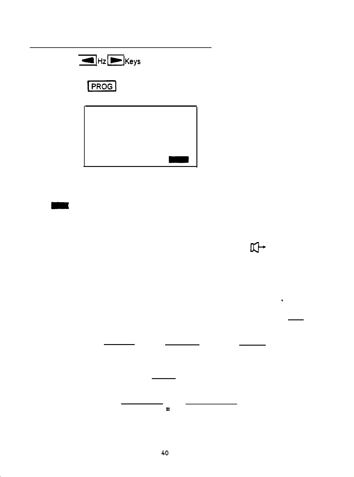
The altitude calibration mode can only be entered when the TM 262 is
powered up from its “off” state while the PROGRAM mode button,
is depressed. Hold the PROGRAM button for approximately
PROG
PROG
five seconds.
STEP 1
When entering the altitude mode the display will read as follows:
Altitude Mode
ECV 2.0
3
9.99
cm
Standard
(E71) is displayed in the bottom right corner of the display until the probe is
in the 2.0 cm
STEP 2
Place the probe into the 2.0 cm
check cm
STEP 3
If the measured volume is not within the published table value ±0.1cc, then
the operator should exit the altitude mode by pressing the PROGRAM
button and contact field service.
Providing the measured volume agrees with the published table ±0.1cc,
the operator may proceed with the altitude adjustment.
STEP 4
With the probe still in the 2.0 cm
enter the custom calibration mode. Custom will appear on the fourth line
of the display.
3
cavity.
3
3
value against the altitude correction table for accuracy.
cavity provided with the instrument and
3
cavity, select the PAGE button to
PAGE
PROG
STEP 5
The value now displayed in the cm
3
display area is the volume measured
and adjusted to the current altitude. If the value displayed is 2.0 cc, then
the volume is adjusted to the current site. If the value is not 2.0 cc ±0.1,
then press the SAVE button to customize the volume measurement
M+
to the current altitude. The measured volume should now read 2.0 cc.
STEP 6
To exit the altitude mode, press the PROGRAM button to return to
PROG
normal mode.
15

2.8 PRETEST AUDIOMETRIC CHECKS
(Models with Audiometer Only)
2.8.1 Noise Recovery Period
Exposure to high levels of sound (e.g., unmuffled lawn mowers, loud
music, gunfire) tends to create a Temporary Threshold Shift (TTS) which
diminishes with time after exposure. Any subject tested soon after such
exposure may exhibit a hearing loss that does not reflect his/her normal
hearing threshold. This test procedure, therefore, generally prescribes a
16 hour interval between the last exposure to high-level sounds and the
administration of any hearing test.
2.8.2 Elimination of Ambient Noise
Excessive noise in the test environment during audiometric testing,
such as that produced by conversation, computers and public address
systems reduces test validity because it tends to mask the test signals,
particularly at the lower frequencies where earphone cushions provide
less effective attenuation. An acoustically-treated room may be
required if ambient noise reaches objectionable levels, i.e., sufficient
to cause apparent hearing loss at the low frequencies. Also, earphone
sound enclosures are available from Welch Allyn as an optional
accessory. If the person being tested is in the same room as the
audiometer, it is recommended that he/she be seated about three
feet (one meter) away from the TM 262TM Auto TympTM.
Maximum permissible noise levels are specified by the American National Standards Institute—Criteria for Permissible Background Noise
during Audiometric Testing, ears covered with earphones (S3.1-1991
revised). Table 2-3 shows the maximum background levels that can be
present inside the room while a valid hearing test is being conducted.
For more comprehensive information about hearing testing and hearing
conservation, refer to the Bibliography.
TABLE 2-3: Permissible Noise Levels
Test Tone
Frequency (Hz) 125 250 500 750 1000 1500 2000 3000 4000 6000 8000
Test Room
Ears covered 34.0 22.5 19.5 21.5 26.5 26.5 28.0 33.5 34.5 38.0 43.5
maximum
permissible octave
band levels
Ears covered
maximum
permissible one-third
octave band levels
29.0 17.5 14.5 16.5 21.5 21.5 23.0 28.5 29.5 33.0 38.5
16

2.9 BIOLOGICAL CHECK
To determine that your TM 262 is functioning properly, perform a daily
check on a normal ear—your own if possible. This allows you to listen
for the probe tone and the stimulus tone (during reflex) and determine if
the air-pressure system is working properly. Keep a copy of your chart
for a day-to-day reference in checking your TM 262.
If you purchased the TM 262TM Auto TympTM with audiometry, select the
AUDIOMETRY button located in the center section of the front
panel. Note that the display changes to an audiogram format. The Hz
and Hz buttons allow you to select each frequency and the dB
HL knob allows you to alter the intensity of each frequency. Position the
test headset on your head so that each earphone is covering the appropriate ear (i.e., red is right and blue is left). Select the right earphone
by pressing the front panel button labelled R and check for the following while depressing the present bar:
• Depressing the Hz button causes the frequency to change to
a lower frequency, depressing the Hz button causes the frequency to change to a higher frequency.
• Each frequency or tone is pure, i.e., there is no distortion or
crackling sound present.
• Rotating the dB HL knob in a clockwise direction increases in
intensity of the tone.
• Rotating the dB HL knob in a counter-clockwise direction decreases the intensity of the tone.
AUD
17

Specifications
STANDARDS:
IEC 601-1 Medical Electrical Equipment Requirements for Safety
CSA C22.2 No. 601-1-M90 Electromedical Equipment,
Warnock Hersey Listed
ANSI S3.39-1987 Aural Acoustic Impedance Admittance (Type 3)
IEC 1027-1991 Aural Acoustic Impedance/Admittance (Type 3)
ANSI S3.6-1989 Audiometers (Type 4)
IEC 645-1 Pure Tone Audiometers (Type 4)
TYMPANOMETRY/REFLEX MODES:
Probe Tone: 226 Hz, ± 3%
Sound Pressure Level: 85.5 dB SPL, ± 2.0 dB,
measured in a 2.0 cm3 coupler
Harmonic Distortion: <5%
Admittance (Compliance) Range: 0 to 1.5 cm
0 to 3.0 cm
NOTE:
1. The range is automatically selected based upon the amplitude
of the compensated (tymp only) tympanogram.
2. The maximum uncompensated (ECV + tympanogram peak)
admittance (compliance) range is 0 to 5.0 cm3.
3. ECV/cavity limits for initiating pressurization is 0.2 to 6.0 cm3.
Compliance Accuracy: ± 0.1 cm3 or ± 5%, whichever is greater
3
3
PNEUMATIC SYSTEM
Pressure Range: +200 to –400 daPa
NOTE:
1. 1 daPa = 1.02 mm H20
2. Pressure sweeps to at least –100 daPa. To save test time,
pressure sweep stops once tympanogram returns to baseline
after –100 daPa.
3. Full pressure sweep for 6 cm3 from sea level to 7000 ft.
altitude with no leak.
Pressure Accuracy: ±10 daPa or ±15%, whichever is greater
56

Rate of Sweep: 600 daPa/sec except near tympanogram peak
where sweep rate slows to 200 daPa/sec to provide better
definition of peak compliance.
Direction of Sweep: Positive to negative
Tympanometric Test Time: approximately one second
NOTE:
High compliance tympanograms will take somewhat longer
Gradient: Tympanogram pressure width at 50% of peak
compliance.
ACOUSTIC REFLEX STIMULI:
Frequencies: 500, 1000, 2000, and 4000 Hz
Accuracy: ±3%
Total Harmonic Distortion: <5%
Rise/Fall Time: 5 to 10 msec
Output Levels:
IPSI: 500 and 4000 Hz:80, 90, 100 dB HL
1000 and 2000 Hz: 85, 95, 105 dB HL
NOTE:
1. Ipsi stimuli are time multiplexed with probe tone
(106 msec ON, 53 msec OFF).
2. Stimuli are presented at lowest level first. If there is no
response, the intensity is increased by 10 dB until a
response is detected or the maximum dB HL is reached.
Pressure: Automatically set to pressure at peak compliance with
an offset of –20 daPa.
Reflex Determination: Compliance change of 0.05 cm3 or greater.
Reflex Test Time: 1 to 12 seconds depending upon the number of ipsi
test frequencies selected (four maximum) and intensity required.
Probe LED Indicators:
Steady yellow: occlusion
Blinking green: ready to start testing
Steady green: test in progress
Steady orange: leak
57

AUDIOMETRY MODE (Model No. 26230, No. 26230-RS,
No. 26235 and No. 26235-RS only— marked “Version 4”)
Frequencies: 125, 250, 500, 750, 1000, 1500, 2000, 3000, 4000,
6000, 8000 Hz
Accuracy: ± 3%
Total Harmonic Distortion: < 3% (125 to 3000 Hz measured acous-
tically at maximum dB HL; 4000 & 6000 Hz measured electrically)
Intensity Levels: 125 Hz: –10 to 50 dB HL
500 to 6000 Hz: –10 to 90 dB HL
250 and 8000 Hz: –10 to 70 dB HL
NOTE:
An additional +10 dB is available per frequency via the
+10 dB button.
Accuracy: 125 to 4000 Hz ±3 dB
6000 and 8000 Hz ±5 dB
Step Size: 5 dB
Signal-to-Noise Ratio: > 70 dB in 1/3 octave;
less than –10 dB HL for levels less than 60 dB HL
Rise/Fall Time: 20 to 50 msec
Tone Format (tone is normally off until present bar is depressed):
Continuous: steady when present bar is depressed
Pulsed: 2.5/sec (i.e., 200 msec ON, 200 msec OFF)
FM (frequency modulated): 5 Hz, ±5%
TRANSDUCERS
IPSI: Welch Allyn design
Audiometric Headset: Pair TDH-39 earphones with MX41AR
cushions (60 ohms impedance)—Models No. 26230,
No. 26230-RS, No. 26235 and No. 26235-RS only
(marked “Version 4”)
PRINTER
Paper Roll Length: approximately 80 feet (960")
Tests/Roll: Tymp and Reflex = 420 tests or 210 people
Tymp and Reflex plus one audiogram =
230 tests or 115 people
Speed: approximately 1.5 minutes to print three screens
(including audiogram).
58

POWER
Line Voltage: 120 V (±10%) or 220 V (±10%) or 240 V (±10%)
NOTE:
Wall mount power supply or internal power supply depending
upon country.
Frequency Range: 50 to 60 Hz (±5%)
Line Voltage Current: 0.2 amps at 120 V or 0.1 amps at 240 V AC
Power Consumption: 15 watts maximum while printing.
Low voltage input for wall mount power supplies 10 to 11 VDC
970 mA.
ENVIRONMENTAL
Temperature:
Operating: 60° F to 105° F Storage: –40° F to 140° F
15° C to 40° C –40° C to 60° C
NOTE:
Warm-up time is required if storage temperature is different
from room temperature.
Humidity: 5% to 90%
MECHANICAL
Dimensions: 13.15" W x 14.5" D x 4.3" H
33.66 cm W x 35.56 cm D x 9.53 cm H
Weight: 10 lbs (4.5 kg) net
14 lbs (6.4 kg) shipping
SUPPLIED ACCESSORIES
Instruction Manual #1738-0101
TDH-39 Headset
(Models #26230/#26235 Only) #23223
Test Cavity #26241
Eartips (6 sizes, 2 each) #26100
Paper — 3 rolls thermal 4"
(10.16 cm wide)
CATALOG
NUMBERS
59

CALIBRATION
35

EQUIPMENT REQUIRED FOR CALIBRATION
TYPE 1 SOUND LEVEL METER
ARTIFICIAL EAR
2 cc COUPLER (GSI #1700-2005 OR B&K #DB0138)
9A
(6 cc) COUPLER OR B&K ARTIFICIAL EAR (B&K #4153)
MANOMETER
VOLTMETER (RMS)
FREQUENCY COUNTER
1700-l 030 TEST CAVITY
SMALL STANDARD (SLOTTED) SCREWDRIVER
SMALL PHILLIPS (CROSS) SCREWDRIVER
36

CALIBRATION PROCEDURE
CONFIG.
Confiq.
mode of operation and once programmed should never change. If a new
microprocessor is installed in location XU7 or
programmed. To program the
JP1
and JP3 then power up the unit. Almost immediately after power up the unit will
display
previously installed jumpers. The
DEFAULT DATA LOADING: Durina routine calibration it is not
Default Data.
set of calibration values into EEPROM. Also, if a new microprocessor has been
installed the Default Data loads critical power-up information that the processor requires
for operation into EEPROM. When a new microprocessor or
installed Default Data should be loaded. Load Default Data by setting Dip Switch
positions 6, 7, and 8 to the “ON” position. Set the
then power up the unit. At power-up the display should indicate the unit model and
version number (GSI 38 Version X), the
(Tymp/Reflex
XXX), and the Default Parameters which are currently being loaded into EEPROM
(Loading Audiometer Defautts, Loading Programmed Defautts, or Loading
Defaults). When the Default Data Loading sequence is complete the display will update
to the Main Calibration Mode Menu. At this point Dip Switches 6, 7, and 8 should be
returned to their normally OFF position.
REGISTER: Durinq routine Calibration it is not
Register.
Config.
Programming the
Register Programmed. At this point power down and remove the
Defautt Data Loading
Rev XXX), the Audiometer Software Revision Number (Audiometer Rev
Config.
Config.
Config.
allows
Register establishes the microprocessors
XU34
Register install temporary jumpers (shorts) on
Register is now programmed.
the
technician
Cal/Norm
Tymp/Reflex
necessary
its
Config.
to quickly store an
Switch to the Cal Mode,
Software Revision Number
to
program
Register must be
necessary
Auto/Tymp
to
averaged
Board is
Tymp/Reflex
the
load
The technician may also load an individual set of Default Data by first setting the
desired Dip Switch to the ON position then setting the Cal/Norm Switch to the Cal
Mode position.Dip Switch assignments are as follows:
Dip Switch
6
7
8
Function
Tymp/Reflex
Audiometer Defaults
Programmed Defaults
Defaults
37
Location Loaded
Tymp EEPROM
Audio EEPROM
Audio EEPROM

‘..
NTERING
THE CALIBRATION MODE DIRECTLY (ROUTINE CALIBRATION)
1)
2)
3)
Verify that Dip Switches 6, 7, and 8 are in the OFF position.
Power up the unit.
Slide the Cal/Normal Switch to the Cal Mode position. The display should
appear as follows:
7
CALIBRATION MODES
l
ATTEN
XDUCER
MAX CAL
STIM
CAL
PRINT HEAD CAL
CUSTOM RTL CAL
PROBE
TONE/MIC
CAL
COMPLIANCE CAL
PRESSURE CAL
38

AUDIOMETER CALIBRATION
ATTENUATOR MAXIMUM OUTPUT CALIBRATION: During routine calibration it
should not be necessary to calibrate the Attenuator Maximum Output. However, if
Audiometer Default Data has been loaded then the Attenuator Maximum Output
must be calibrated.
the
1)
2)
3)
4)
5)
Connect the right phone output unloaded
Use the
ATTEN
Press the Present Bar
(The Tone Indicator
Use the
the dB HL knob until the output level for currently display frequency is within the
minimum/maximum values listed in the following table. When the desired output
level has been reached store the value by pressing the pi Key. Repeat
all frequencies.
!=I
MAX CAL
p/
Hz
Hz
Frequencv
125
250
500
750
1000
1500
2000
3000
4000
6000
8000
[c]
Keys to position the cursor on the 38 display at the
position.
Key
to enter the
0
to lock on the tone.
*
F)
should now be present on the display.
to select the desired frequency for calibration.
(Hz)
.
to
an RMS Meter.
ATTEN
MAX CAL Mode.
Minimum - Maximum
2.05-2.30
2.05-2.30
2.33
-
2.5
1.69-1.9
2.28-2.5 vrms
2.28 -
2.55 -
2.28 -
2.55 -
2.28-2.50
2.28 -
2.5
2.70
2.50 vrms
2.70 vrms
2.50 vrms
vrms
vrms
vrms
vrms
vrms
vrrns
vrms
Adjust
for
After all frequencies have been calibrated press the
Calibration Mode Menu.
39
v]
Key to the Main
AUDIOMETER
Use
1)
the a IHz[m IKeys
STIM CAL.
SPL OUTPUT LEVEL CALIBRATION
to position
the cursor on the
38
display at XDUCER
2)
Press
the
I=]
Key to
enter the XDUCER
STIM
CAL
MODE.
The display should now indicate:
XDUCER
STIM
CAL
40.0
125
dB
Hz
NOTE: Tone Bar is OFF
or Inactive
R
40.0
125 Hz
R
dB
Indicates the Current Hearing Level (HL) selected.
Indicates the Current Frequency (Hz) selected.
Indicates the Current Transducer selected.
Indicates a Steady Tone Presentation
The Tone Bar is active in this mode and serves a dual function. When the Tone Bar
as
is OFF or inactive the current hearing level is displayed
When the Tone Bar is pressed ON or active the stim on indicator
the display and the 40.0
dB
(HL) indicator will update
to
shown above.
will appear on
*
the ANSI Standard Reference
Threshold Level (RTL) measured in Sound Pressure Level (SPL) for the selected
frequency and hearing level.
Example:
40.0 dB (HL) at 125 Hz (Freq) will update to 85.0 dB SPL
when the Tone Bar is depressed.
Given:
Therefore:
The ANSI Standard (RTL) correction value for 125 Hz at 0 HL is
dB
equal to 45.0
At 40 dB HL which
Hz
125
will equal 85.0 dB SPL.
SPL.
is
For 125 Hz
ANSI Standard RTL for 0 dB HL
(+)40
dB HL
dB
40
HL
.
40 dB SPL higher that 0 dB HL the output for
=
=
=
40
45.0 dB SPL
(+)40.0 dB
85.0 dB SPL
SPL

For 8
KHz
When calibrating using a Sound Level Meter (SLM) it is important to add or subtract the
appropriate microphone correction.
manufacturer or calibration facility should supply the microphone’s frequency response
curve.
response by using a piston phone or similar standard device. Below is an example of
a microphone frequency response curve.
MICROPHONE
CALIBRATION
ANSI Standard RTL for 0. dB HL
(+)60 dB
dB
60.
HL
HL
=
=
=
13.0 dB SPL
(+)
60.0 dB SPL
73.0 dB SPL
When the microphones are calibrated the
The microphone is then calibrated to the SLM which has a flat frequency
l
CHART
5
dB
+1
0
-1
-5
Provo,
Utah
-10
. .._,..., .q , , ,
I
-15
20 Hz 50 1DO
.,-_i..,
! I. ._ ! i, _
.I 11 1
._,‘_.,.., 1,. __, _,._ ,
200 ' 500
1K
2K
5K
10K
--1-\I--s’
20K
50K
The curve shows that the microphone response is flat between 20 Hz and 1.5 KHz,
KHz
high between 2
as
an example when a standard force is applied to the surface of this microphone its
dB
output is 1
1 dB to our expected value. Our formula for determining the proper calibration
add
high. Therefore, when calibrating 4
and 6
KHz,
and low at frequencies 8 KHz or greater. Using 4 KHz
KHz
using this microphone we must
level for 4 KHz is as follows:
100k'
200K
. 41

4
KHz
ANSI Standard RTL for
Reference HL for Calibration
(+)80. dB
(+) or (-) Microphone Correction
0. dB HL
NA.
80.
dB
=
HL
=
HL
=
(+)80.0 dB
(+)
9.5 dB SPL
SPL
1.0 dB SPL
90.5 dB SPL
The following table contains the ANSI Standard Reference Threshold Levels
RTL's
at
0 HL for each frequency when using TDH-39P earphones.
Frequency (Hz)
ANSI Standardd
Measured
in dB SPL
RTL
125
45.0 25.5
Standard Reference Threshold Levels re:
250
11.5
500 750 1000 1500
7.5
20pPa
7.0 6.5
for
Telephonics
2000 3000
9.0
10.0
TDH-39P earphones
4000
0.5
as measured on the National Bureau of Standards 9-A coupler. Reference ANSI S3.6
6000 8000
15.5 13.0
-
1989, ISO 389 - 1975 Standards.
Grason-Stadler has made an effort to minimize calibration time by defaulting the
Reference HL Levels for Calibration to maintain an expected SPL Calibration Level of
between 85 and 95 dB SPL. The Default HL Levels are as follows:
Frequency
Default HL
(Hz)
125 250 500 750 1000 1500
40
60 80 80 80 80
2000 3000
80 80 80 80 60
4000
6000
8000
Because the 38 automatically adds the ANSI RTL and reference HL values on the
display (when the Tone Bar, is active) the technician needs only to add or subtract
the appropriate microphone correction to the displayed value when calibrating.
3)
4)
5)
Connect the right ear phone to the Sound Level Meter Artificial Ear.
Press (TONE BAR\ the display will update from the selected hearing level to
the ANSI Standard RTL value for calibration and the
appear).
indicator will
m+
Adjust the HL knob until the SPL Level measured on the SLM for the selected
frequency and transducer equals the value indicated on the 38 display (+ or
’
-
Microphone Correction).
6)
7)
Press
Repeat for all frequencies, right phone, left phone, ipsi and contra by
theIF
Key to store the data in memory.
selecting the appropriate key on the 38 front panel.
NOTE: Both left phone and right phone must be calibrated.
-
8)
When finished press the
Menu.
vl
Key to return to the Main Calibration Mode

CUSTOM RTL CAL
This mode is used primarily if a customer wants to calibrate using transducers other
than TDH-39P earphones. This mode allows the technician to program different
RTL values to be displayed when calibrating using the XDUCER
Once programmed, the Custom RTL values will be displayed each time the
XDUCER
63.5
Audiometry Mode is selected to indicate to the customer that Custom RTL values
have been programmed. To return to the ANSI Standard Values and extinguish the
#
sign, the technician must load Audiometry Default Calibration Data.
1)
STIM
CAL MODE is entered. The range of allowable
dB
A # sign will appear next to the dB HL indicator on the display when
Use
theF]Hz]=]Keys
display.
to position the cursor at Custom RTL Cal on the
STIM
CAL MODE.
RTL's
is -5 dB to
2)
3)
4)
5)
6)
7)
NOTE:
PROBE
Press the
Press
Adjust the dB HL dial to achieve the desired RTL value.
Store the value into memory by pressing the m Key.
Repeat for all desired frequencies.
Press
Use
Mode
IFZF]
thewlHz[c]Keys
the
]w]
Adjusting the Custom RTL values has no effect on the earphone
output level. After storing the Custom
must calibrate to the appropriate levels using the XDUCER
CAL MODE.
TONE/MIC
theI=] HzF]Key
position.
CAL
Key to enter the Custom RTL Cal Mode.
to select the desired frequency.
Key to return to the Main Calibration Menu.
RTL's
to position the cursor at the Probe
the technician
Tone/Mic
STIM
Cal
2)
Press the ) PROG 1 Key to enter Probe Tone/Mic Cal Mode. The display will
update to the following “flashing” display.
PROBE
ECV
At this point place the probe in the 2 cc coupler on the Sound Level Meter.
TONE/MIC
SLM
CAL 1.1
43

3)
Press the
m
Key and the display will stop flashing.
4)
5)
6)
Use the dB HL dial to adjust the Probe Tone Level to 85.5 dB SPL
dB).
At this point the Probe Tone
226 Hz
Press the
(+/-
6 Hz).
LM+f
Key to store the data in memory. The display will update to
Frequency
may be verified. It should equal
the following ‘Washing” display.
j:l’:,‘““““*“‘I
.
At this
Press the
point
place the probe in the 2 cc test cavity.
m
Key to start the microphone calibration process. The display
will update to the following steady state display.
**I
(+/-
0.9
After a few seconds the SAVED indicator will extinguish and the 1.2
will change to 1.3. When the cycle is complete the display
following “flashing” display.
7)
Press the
,
~
-
COMPLIANCE CAL
1)
Use the
F]
Mode position.
2)
Press the
[=I
update to the following “flashing” display.
Hz
will update to the
Key to return to the Main Calibration Mode Menu.
-
LqKeys
to position the cursor
Key to enter the Compliance
at the Compliance Cal
Cal Model The display will
indicator
44
COMPLIANCE CAL 2.1
ECV 0.5
3
cm
3)
4)
Place the probe into the 0.5 cc calibration cavity then press the
[M+I
Key to
start the 0.5 cc calibration. The display will stop flashing and remain in steady
state to indicate that calibration is in progress.
NOTE: If the wrong cavity size is used the display will indicate E74 in the lower
right hand corner. After approximately 5 seconds the ERROR MESSAGE will
extinguish and the calibration process may be continued by placing the probe
into 0.5 cc cavity and then pressing the
[WI
Key.
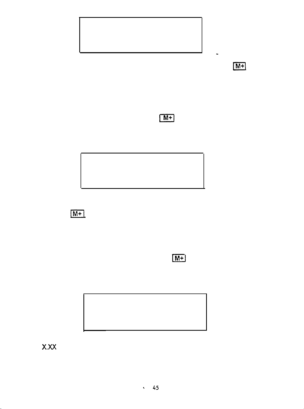
When the 0.5 cc calibration is complete the display will update to the following
“flashing” display.
COMPLIANCE CAL 2.2
ECV 2.0
3
cm
At this point place the probe into the 2.0 cc test cavity.
Press the
PI
Key to start the 2.0 cc calibration. The display will stop flashing
and remain in steady state to indicate that calibration is in progress.
NOTE: If the wrong cavity size is used the display will indicate E74 in the lower
right hand corner.
After approximately 5 seconds the ERROR
MESSAGE
extinguish and the calibration process may be continued by placing the probe
into the 2.0 cc cavity and then pressing the
m]
Key.
When the 2.0 cc calibration process is complete the display will update to the
following steady state display.
COMPLIANCE CAL 2.3
ECV 2.0
cm3
X.XX
X.XX
is equal to the current volume measurement.
.
45

The calibration of compliance measuring devices is affected by air density. As
the air gets thinner, the volume measurement in a
hardwall
cavity increases.
Therefore, as you go up in altitude, barometric pressure decreases making the
hardwall
cavity appear larger than it is.The GSI 38 allows the flexibility to
display the real altitude effect or to correct the ear canal measurements relative
to sea level.
A)
If the customer prefers to correct the ear canal volumes relative to sea
level then adjust
2.00 After adjusting to the desired level store the value by pressing
the
]m
compliance calibration process is complete.
B)
If the customer prefers uncorrected ear canal volumes (actual at altitude
measurements) then adjust the
value indicates the appropriate volume measurement for the customer site
elevation according to the following altitude table.
Altitude
(ft)
0
500
1000
1500
2000
2500
3000
3500
4000
4500
5000
5500
6000
6500
7000
7500
8000
8500
9000
9500
10000
Barometric Pressure
(mm
thep]HzlF]
Keys until the cm3 XXX value equals
Key. The display will start “flashing” indicating that the
i-1
Hz
[Fj
Keys until the cm’ XXX
Expected Volume Reading
Hg)
759.97
746.51
733.04
719.84
706.63
693.93
681.23
668.78
656.34
644.40
632.46
620.78
609.09
598.00
588.00
578.00
568.00
555.00
544.00
533.00
522.00
*
at Altitude (cc)
2.00
2.01
2.03
2.05
2.07
2.09
2.11
2.13
2.15
2.17
2.20
2.22
2.25
2.27
2.30
2.34
2.37 2.4~0.1
2.40
2.44
2.49 2.520.1
2.54
Calibration Volume
at
Altitude
(cc)
2.0
2.020.1
2.020.1
2.020.1
2.120.1
2.120.1
2.120.1
2.120.1
2.2zo.q
2.220.1
2.220.1
2.220.1
2.220.1
2.3~O.q
2.3~0.1
2.320.1
2.4~0.1
2.4~0.1
2.520.1
5)
Press the
]M+j
Key to store the customer altitude volume measurement. The
display will start “flashing” indicating that the Compliance Calibration process is
complete.
Press the
m]
Key to return to the Main Calibration Mode Menu.
46

PRESSURE CAL
1)
2)
3)
Use the
Press the
update to the following “flashing” display.
At this point make sure that the probe tip is in open air.
Press
Pressure Calibration is complete the display will update to the following “flashing”
display.
[~~Hz~~~
I-1
I
1
M+ 1 Key to start the Ambient Pressure Calibration.
Keys to position the
Key
to enter the Pressure
‘PRESSURE CAL
ECV OPEN
A/D
daPa
cursorr
at the Pressure Cal position.
Cal Mode. The display will
3.1
When the
Ambient
.
PRESSURE
ECV MANOMETER
A/D
XXXX
daPa
-200
CAL
3.2
4)
5)
6)
At this point connect the probe tip to a manometer.
NOTE: Manometer internal volume must be less than 5 cc’s.
Press the
Use the
to -200
Press the
saved will appear in the lower right hand corner of the display. After 3 to 5
seconds the saved indicator will be extinguished and the display will update to
a steady state display as follows.
At this point verify that the leak rate is less than 2
Press the
manometer reading is within &15%) of the pressure value indicated on the 38
display.
Press the
-1
IzIHz [=I
daPa &15%)
wi
1-1
Ver
/=I
Key. At this point the pump will pressurize to -200
Key to store the -200
Key and the 38 will pressurize to +200
Key to return to the Main Calibration Mode Menu.
daPa
.
Keys to adjust the pressure on the external manometer
daPa
Calibration data. The messages
daPa/sec:
daPa.
47

PRINT HEAD CAL
1)
2)
3)
Use the
Press
Press the
1x1 HzLG]
the
-1
[=I
Keys to move the cursor at the Print Head Cal position.
Key to enter the Print Head Cal Mode.
Hz to lighten
the
printout and the
[=I
Hz Key to darken the
printout. When either key is pressed the printer will print a test pattern (the
alphabet) on a single line. When the center of the adjustment range is crossed
the In Range indicator on the display will appear (when adjusting from a light
intensity to a dark intensity) or extinguish (when adjusting from a dark intensity
to a light intensity).
EXAMPLE
TOTAL RANGE
OF PRINT INTENSITY ADJUST RANGE.
=
20 STEPS OR 20 DIFFERENT INTENSITY LEVELS.
ABCDEFGHIJKLMNOPQRSTUVWXYZ:
ABCDEFGHIJKLMNOPQRSTUVWXYZ:
ABCDEFGHIJKLMNOPQRSTUVWXYZ:
ABCDEFGHIJKLMNOPQRSTUVWXYZ:
ABCDEFGHIJKLMNOPQRSTUVWXYZ:
ABCDEFGHIJKLMNOPQRSTUVWXYZ:
ABCDEFGHIJKLRNOPQRSTUVWXYZ:
ABCDEFGHIJKLRNOPQRSTUVWXYZ:
ABCDEFGHIJKLMNOPQRSTUVWXYZ:
ABCDEFGHIJKLMNOPQRSTUVWXYZ:
l ABCDEFGHIJKLNNOPQRSTUVWXYZ:
l ABCDEFGHIJKLMNOPQRSTUVWXYZ:
l ABCDEFGHIJKLMHOPQRSTUVWXYZ:
l
ABCDEFGHIJKLMNOPQRSTUVWXYZ;
l ABCDEFGHIJKLMNOPQRSTUVWXYZ:
l ABCDEFGHIJKLMNOPQRSTUVWXYZ:
l ABCDEFGHIJKLMNOPQRSTUVWXYZ:
l ABCDEFGHIJKLMNOPQRSTUVWXYZ:
lABCDEFGHIJKLMNOPQRSTUVWXYZ:
l ABCDEFGHIJKLMNOPQRSTUVWXYZ:
l “In Range” indicated on display.
4)
5)
6)
Press
Press the
Slide the Cal/Norm Switch to Norm to return to Normal Mode Operation.
the[F]
1-1
Key to store the desired intensity value.
Key to return to the Main Cal Mode Menu.
. 48

S4 DIP SWITCHES.
S1
S2
S3
S4 _
S5
S6
S7
S8
Unused
Factory Auto
To Be Defined
To Be Defined
To Be Defined
Tymp/Reflex Default Data
Audiometer
Program Default Data
ON
Cal
Default
Data
Unused
Norma! Cal Mode Operation
Normal Cal Mode Operation
Normal Cal Mode Operation
Normal Cal Mode Operation
Normal Cal Mode Operation
Normal Cal Mode Operation
Normal Cal Mode Operationon
*
OFF
49

TROUBLE SHOOTING
50

ERROR MESSAGES (EXX)
NOTE: If an Error Message is observed the associated code number should be
recorded for future reference.
specific block of circuitry which will enable the technician to repair the problem in a fast,
efficient manner. Most software errors are related to poor environmental conditions
such
as static electricity and power line interference and will generally clear with power
down/up. Contact your local sales and service organization and supply them with the
Error Code Number if the error will not clear with power down/up.
AUDIOMETER PROCESSOR RELATED MESSAGES
The Error Code Number is designed to point to a
Code Number
EPROM Checksum Error on power up / if
01
02
03
04
05
Description/Possible
non-recoverable possible defective
Board EPROM
Microprocessor Internal RAM Error on power up / if nonrecoverable replace Microprocessor U34.
Watch Dog Timer Timeout / the Watch Dog Timer Circuit
monitors the Microprocessor’s operation. The Processor
must periodically send an “I’m Okay” message ‘to the watch
dog or the watch dog will halt all operations. If non-
recoverable try replacing.
Audiomymp Board.
Microprocessor
defective crystal Y2 or Microprocessor U34.
Undefined Interrupt Error / this type of soft error should
always be recoverable.
Processor does not acknowledge or cannot execute. If nonrecoverable replace Audiomymp Board.
U30
Clock Failure / if non-recoverable possible
Cause
Auto/Tymp
or Microprocessor U34.
Microprocessor U34 or
It
relates to an Interrupt that the
06
07
08
Opcode Trap Interrupt Error /this type of error code should
always be recoverable.
Microprocessor
External
Audio RAM U32 or Microprocessor
Normal or Swap Stack
should always be recoverable.
Audio/Tymp Board.
RAM
U34
or Audiomymp Board.
Error / if non-recoverable possible defective
Overflow
51
If non-recoverable replace
U34.
into the Global Variables
If
non-recoverable replace
/

Code Number
Description/Probable Cause
09
10
'12
‘13
'14
'15
Conf. Register Error / if non-recoverable re-calibrate
Config,
Register then replace Microprocessor U34.
Halt in Response to Remote Command
/
if non-recoverable
possible defective Audio/Tymp Communications Chip U36
or Microprocessor
Invalid
Keycode
U34.
detected in CMDTSK / if non-recoverable
possible defective Switch Panel, Switch Buffer U26, U27, or
U28, or Microprocessor U34.
Invalid
Invalid
Keysource detected in CMDTSK
Queue Power
Error detected in CMDTSK /same as
/
same as above.
above.
Bad Pointer to EEPROM Routine’/
Collision of the Normal Stack and Swap
Stack
/
‘16
‘17
'18
'19
‘20
‘21
22
Invalid function for a Banded Swapped Function
Printer RAM Error on power up / internal or micro
Tymp Hardware State is unknown
Non-Fatal Audiometer related error messages
Calibration Data Read Error
HL Limit exceeded /
Invalid Extended Range Selection due to HL not in range
where the Extend Range is valid
23
24
Calibration Data Write Error occurred
Invalid Present Bar Operation due to a
Calibration Data Error /
/
/
occured /
/
/
52

Code Number
Description/Probable Cause
25
Remote Record received with a Bad Record Format, invalid
Key Code, or Invalid Record Type
26
27
28
EEPROM Checksum Error
EPROM TO EEPROM Data Load Error
Remote Command received from an external remote device
(factory auto
unsupported record type
29
Remote command received from an external remote device
(factory auto cal) which is ignored due to mode
30
GSI vs Custom RTL Calibration status Read Error from
EEPROM
31
32
Printer Calibration Data Read Error
No test available to print
/
/
/
cal)
which is invalid due to mode or is an
/
/
/
/
/
33
34
35
36
37
38
39
40
Tymp/Reflex
the Audio Processor or the
setting the Synch
No Free Memory available when going to a new test
Processor not responding to a command from
Tymp/Reflex
Processor is not
Stimo line on power up /
/
Invalid test type read from memory when trying to display
Print Head initialization failed /
Printer Ambient temperature out of Range
Record was received from the
Tymp/Reflex
/
Processor which
has a valid format but the record type was not the type
expected
/
Call Factory for instruction
Audiometry mode not enabled

TYMP
PROCESSOR RELATED MESSAGES
Code Number
51
52
53
54
55
56
57
58
59
60
Description/Probable Cause
EPROM Checksum Error on power up
Internal RAM Error on power up
Watch Dog Timer Time Out
CPU Clock Failure
Undefined Interrupt Error
/
/
Opcode Trap Interrupt Error
External RAM Error
Stack Overflow Error
Config.
Register Error
/
/
/
Bad Pointer to EEPROM Routine
/
/
/
/
/
61
62
63-69
70
71
72
73
74
75
EEPROM Read Error in Norm or
Couldn’t Home Pump
/
Alt
Mode
/
Undefined
Non Fatal Errors
Probe is occluded or in cavity at power up
/
Probe not in 2.0 mL cavity during Altitude Adjustment Cal
Mode
End of gain reached in Microphone Cal Mode
/
Probe Tone Gain Error during Probe Tone Gain Verification
/
Cavity Error during Calibration /
Compliance Calibration Error /
76
Unused
54

Code Number
77
Description/Probable Cause
A/D
Pressure Value out of range of Pressure Transducer
Gain
Error /
78
79
80
Remote Record Error
Non-Fatal Cal Data
Reflex Test
time /
81
82
83
84
Remote Command invalid for the mode
Leak or Occlusion Error
Pump end of stroke
Undefined Error Number Reported /
/
Read/Write
info
not received for the Audio within the allotted
Error
/
/
/
/
55
 Loading...