


 Loading...
Exam/Procedure Light
Operation Manual
Service Manual
LCI-100/200 Illumination
and Imaging System
Services LCI-100, LCI-200,
LCI-200CE and LCI-200S
VA316
Rev. D

ì |
/&,рмннолннэ6HUYLFHэ0DQXDOэ |
5HYпэ'сэжокнодз |

To Service Personnel:
The information in this manual is subject to change without notice and should not be construed as a commitment by Welch Allyn, Inc.
Welch Allyn assumes no responsibility for any errors that may appear in this manual. If the product and/or its operation varies significantly from any description herein, please contact the Welch Allyn Imaging Products Group Product Service Department at 4619 Jordan Road, Skaneateles Falls, New York 13153, (315) 685-4108.
This product has been designed to provide a high degree of safety and reliability. However, we can not guarantee against the deterioration of components due to aging and normal wear.
All service and repairs must be performed by authorized Welch Allyn personnel or agents, using Welch Allyn replacement parts. Failure to do so will invalidate the product warranty.
Authorized service centers should refer to repair specification P02355 (Level 1) or P02113 (Level 2) for proper test and device history record requirements.
Please refer to the product warranty for specific coverage.
Welch Allyn, Inc. Imaging Products Group 4619 Jordan Road
Skaneateles Falls, New York 13153 USA
(315) 6854108
ë |
/&,рмннолннэ6HUYLFHэ0DQXDOэ |
5HYпэ'сэжокнодз |

Limited Warranty
Welch Allyn warrants the LCI-100/200, when new, to be free of defects in material and workmanship and to perform in accordance with manufacturer's specifications when subjected to normal use and service for a period of one year from the date of purchase from Welch Allyn or an authorized agent. Welch Allyn will either repair or replace any components found to be defective or at variance from manufacturer's specifications within this time at no cost to the customer. It shall be the purchaser's responsibility to return the instrument directly to their authorized distributor, agent or service representative.
This warranty does not cover the Hi-LUX lamp, breakage, or failure due to tampering, misuse, neglect, accidents, improper installation, modification, or shipping, or to improper maintenance, service, and cleaning procedures. This warranty is also void if the instrument is not used in accordance with manufacturer's recommendations or if repaired or serviced by other than Welch Allyn or an authorized agent. Purchase date determines warranty requirements. No other express or implied warranty is given.
For service assistance or questions regarding this warranty, please call Welch Allyn product service at (315) 685-4108.
ê |
/&,рмннолннэ6HUYLFHэ0DQXDOэ |
5HYпэ'сэжокнодз |

é |
/&,рмннолннэ6HUYLFHэ0DQXDOэ |
5HYпэ'сэжокнодз |

Table of Contents
SECTION 1: General Information . . . . . . . . . . . . . . . . . . . . 1-1
Introduction . . . . . . . . . . . . . . . . . . . . . . . . . . . . . . . . . . . . . |
1-1 |
Basic System Description . . . . . . . . . . . . . . . . . . . . . . . . . . |
1-1 |
Specifications . . . . . . . . . . . . . . . . . . . . . . . . . . . . . . . . . . . |
1-4 |
System Symbol Descriptions . . . . . . . . . . . . . . . . . . . . . . . |
1-5 |
SECTION 2: Service . . . . . . . . . . . . . . . . . . . . . . . . . . . . . . . |
2-1 |
Intent of Manual . . . . . . . . . . . . . . . . . . . . . . . . . . . . . . . . . |
2-1 |
Required Tools . . . . . . . . . . . . . . . . . . . . . . . . . . . . . . . . . . |
2-1 |
Words of Caution . . . . . . . . . . . . . . . . . . . . . . . . . . . . . . . . |
2-2 |
Performance Check . . . . . . . . . . . . . . . . . . . . . . . . . . . . . . |
2-3 |
Calibration . . . . . . . . . . . . . . . . . . . . . . . . . . . . . . . . . . . . . |
2-5 |
SECTION 3: Problem Solving . . . . . . . . . . . . . . . . . . . . . . . 3-1
Troubleshooting . . . . . . . . . . . . . . . . . . . . . . . . . . . . . . . . . 3-1
Connector Pinouts . . . . . . . . . . . . . . . . . . . . . . . . . . . . . . . 3-7
SECTION 4: Disassembly and Repair . . . . . . . . . . . . . . . . |
. 4-1 |
Front Panel . . . . . . . . . . . . . . . . . . . . . . . . . . . . . . . . . . . . . |
4-2 |
Rear Panel . . . . . . . . . . . . . . . . . . . . . . . . . . . . . . . . . . . . . |
4-4 |
Chassis Assembly . . . . . . . . . . . . . . . . . . . . . . . . . . . . . . . |
4-6 |
Ballast Assembly . . . . . . . . . . . . . . . . . . . . . . . . . . . . . . . . |
4-8 |
LEMO Pin-out . . . . . . . . . . . . . . . . . . . . . . . . . . . . . . . . . . |
4-10 |
Disassembly and Replacement Procedures . . . . . . . . . . |
4-11 |
SECTION 5: Maintenance . . . . . . . . . . . . . . . . . . . . . . . . . . |
5-1 |
Preventative Maintenance . . . . . . . . . . . . . . . . . . . . . . . . . . 5-1
Checking Ground Impedance . . . . . . . . . . . . . . . . . . . . . . 5-2
Measuring Leakage Current . . . . . . . . . . . . . . . . . . . . . . . . 5-2
SECTION 6: Theory of Operations . . . . . . . . . . . . . . . . . . . 6-1
Introduction . . . . . . . . . . . . . . . . . . . . . . . . . . . . . . . . . . . . . 6-1 Start Up Routine . . . . . . . . . . . . . . . . . . . . . . . . . . . . . . . . . 6-1 Power Supply . . . . . . . . . . . . . . . . . . . . . . . . . . . . . . . . . . . 6-1 Light Control board . . . . . . . . . . . . . . . . . . . . . . . . . . . . . . . 6-2 Video Output Board . . . . . . . . . . . . . . . . . . . . . . . . . . . . . . . 6-3 Camera Processor Module . . . . . . . . . . . . . . . . . . . . . . . . . 6-4 Delay Line Board . . . . . . . . . . . . . . . . . . . . . . . . . . . . . . . . . 6-5 Ballast Board . . . . . . . . . . . . . . . . . . . . . . . . . . . . . . . . . . . . 6-5
APPENDIX A: Schematics/Diagrams |
7-1 |
APPENDIX B: Camera Head Assembly Diagram |
8-1 |
Rev.
D
D
D
D
D
D
Date
4/2/96
4/2/96
4/2/96
4/2/96
4/2/96
4/2/96
è |
/&,рмннолннэ6HUYLFHэ0DQXDOэ |
5HYпэ'сэжокнодз |

ç |
/&,рмннолннэ6HUYLFHэ0DQXDOэ |
5HYпэ'сэжокнодз |

Table of Illustrations
FIGURE 1: LCI-100/200 Basic System . . . . . . . . . . . . . . . . . . . . . . 1-1 FIGURE 2: Functional Block Diagram . . . . . . . . . . . . . . . . . . . . . . 1-2 FIGURE 3: Rear Panel View . . . . . . . . . . . . . . . . . . . . . . . . . . . . . . 1-3 FIGURE 4: Front Panel View . . . . . . . . . . . . . . . . . . . . . . . . . . . . . 1-3
FIGURE 5: Front Panel Assembly (Exploded View) . . . . . . . . . . . 4-3
Parts List . . . . . . . . . . . . . . . . . . . . . . . . . . . . . . . . . . . . . . . . . . . . . 4-2
FIGURE 6: Rear Panel Assembly (Exploded View) . . . . . . . . . . . . 4-5
Parts List . . . . . . . . . . . . . . . . . . . . . . . . . . . . . . . . . . . . . . . . . . . . . 4-4
FIGURE 7: Chassis Assembly (Exploded View) . . . . . . . . . . . . . . 4-7
Parts List . . . . . . . . . . . . . . . . . . . . . . . . . . . . . . . . . . . . . . . . . . . . . 4-6
FIGURE 8: Ballast Bracket Assembly (Exploded View) . . . . . . . . 4-9
Parts List . . . . . . . . . . . . . . . . . . . . . . . . . . . . . . . . . . . . . . . . . . . . . 4-8
FIGURE 9: LEMO Connector . . . . . . . . . . . . . . . . . . . . . . . . . . . . 4-10
FIGURE 10: Leakage Current Diagram . . . . . . . . . . . . . . . . . . . . . 5-3
APPENDIX A: SCHEMATICS/DIAGRAMS . . . . . . . . . . . . . . . . . . . . 7-1
Interconnect Diagram
LCI-100 806777
LCI-200 806945
LCI-200CE 808314
Video Output Driver Board Schematic
Camera LCI Assembly Board Diagram
Light Control Board Schematic
APPENDIX B: CAMERA HEAD ASSEMBLY DIAGRAM . . . . . . . . |
8-1 |
æ |
/&,рмннолннэ6HUYLFHэ0DQXDOэ |
5HYпэ'сэжокнодз |

å |
/&,рмннолннэ6HUYLFHэ0DQXDOэ |
5HYпэ'сэжокнодз |
General Information
Introduction
The Welch Allyn LCI-100/200 Illumination and Imaging System is fundamentally different from any other illumination or video system. In this product, Welch Allyn has combined a compact light source with a very small remote video camera, which can be attached to nearly all rigid or flexible scopes. By engineering both the video and the illumination end of the product, Welch Allyn is able to produce a very small, highly efficient product.
Furthermore, by combining the lighting and imaging in a single package, Welch Allyn has dramatically decreased the burden of system setup, and has eliminated the need for system white balance. The result is a compact, affordable lighting and video system for rigid and flexible endoscopic procedures.
Basic System Description
There are three major components to the LCI-100/200: the Power Box, the Camera Head Assembly, and the Fiber Optic Bundle. The centerpiece of the Power Box is a new
Welch Allyn lamp which produces the same output as a high wattage Xenon arc lamp, but generates only a fraction of the heat. The Welch Allyn lamp produces a virtual "point source" of light, and is specifically designed to couple with a fiber optic bundle. The camera used in the LCI-100/200 is an advanced SONY one-half inch CCD camera. This camera uses the proprietary HyperHAD microlens architecture, whereby a microscopic light gathering lens is positioned over each pixel on the CCD, making the CCD extraordinarily sensitive to light. The SONY also operates in Auto-Shutter mode. The three major components of the LCI-100/200 are shown below.
Figure 1: Welch Allyn LCI-100/200 Illumination and Imaging
System. Pictured are the Power Box, the Fiber Optic Bundle with Universal light post, and the Camera Head, with attached soaking cap and available C-Mount coupler.
1-1 LCI-100/200 Service Manual |
Rev. D, 7/30/96 |

6HFWLRQýì *HQHUDOý,QIRUPDWLRQ
NOTE: The LCI-200 Power Box adds a picture brightness control incorporating light control circuitry and a stepper motor. For purposes of this manual, an
(*) will indicate sections not applicable to the LCI-100 Power Box. The
Camera heads for both the LCI-100 and 200 are identical.
The main circuitry for the LCI-100/200
is found in the power 

 box, and is illustra-
ted below in a functional block diagram.
Figure 2: Functional Block
Diagram of LCI-100/200
Power Box
Major Component Description: Power Box
The LCI-100/200 Power Box is driven by a universal switching power supply, which accept 100-240 VAC, 50/60 Hz without having to be adjusted. This power supply automatically senses line voltage, and makes the correct adjustments for any line input. This power supply is Medical Grade, and is approved for medical standards by UL, CSA, and TUV.
Power is supplied to two primary functions in the Power Box: lighting and video processing. For illumination, a ballast is used to ignite and operate the lamp. The lamp used in the LCI-100/200 is a proprietary Welch Allyn miniature arc lamp, which provides superior illumination in a package only a fraction of the size of typical endoscopic light sources. Both the lamp and the ballast are manufactured by Welch Allyn. Power is also supplied to a SONY Camera, which used to process the video image. A video delay board accounts for the distance between the CCD and the camera processor. A light control board also operates inside the
Power Box; this board analyzes the video signal, and modulates the amount of light through a mechanical light control assembly.
1-2 LCI-100/200 Service Manual |
Rev. D, 7/30/96 |
6HFWLRQýì *HQHUDOý,QIRUPDWLRQ
A video output board provides two S-video and two composite video signal outputs. All of these components are diagrammed in the functional diagram on page 7; front and rear panel diagrams are shown below.
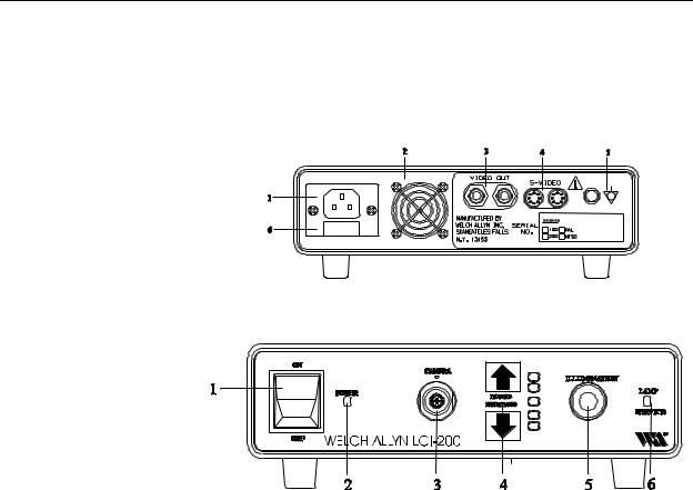
Figure 3: Rear Panel
1. AC Power Input
2. Fan Grill
3. 2 Composite Video
Outputs, BNC Type
4.2 S-Video Outputs
5.Potential Equalization Stud
6.Fuse Drawer
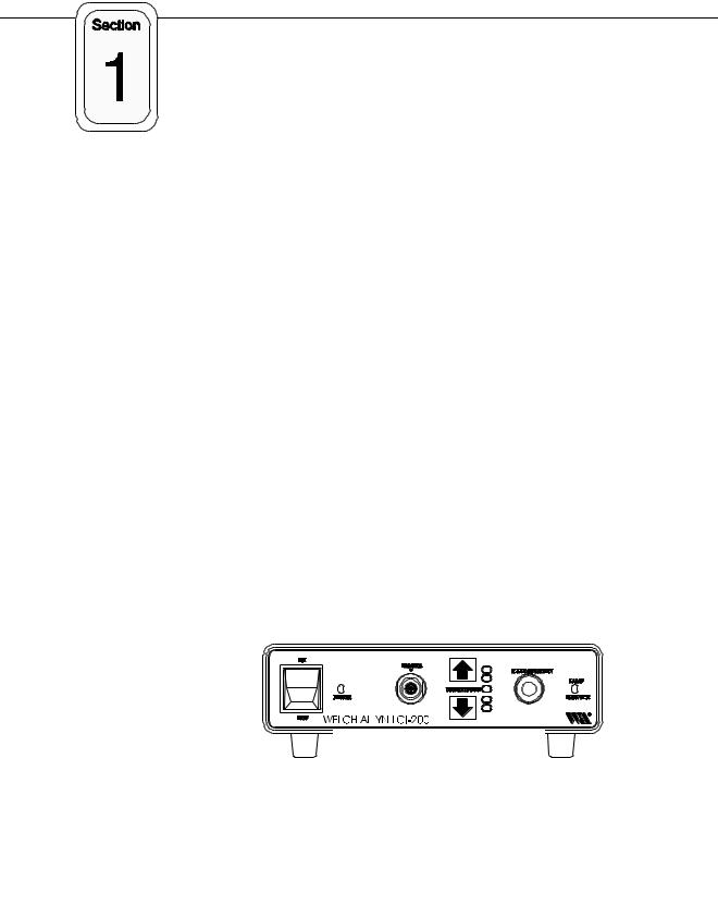
Figure 4: Front Panel
1. Power Switch
2. Power Indicator
3. LEMO Connector
4. Picture Brightness Control
5. Light Port
6. Lamp Service Light
Major Component Description: Camera Head
The camera head assembly is made of a SONY 1/2 inch CCD packaged into a handpiece, a ten foot video cable with LEMO connector, and a soaking cap. A C-
Mount optical coupler is a separate component which screws onto the camera head. The CCD used incorporates the new HyperHAD architecture, making the chip extremely sensitive to light.
Major Component Description: Fiber Optic Bundle
A 5mm diameter fiber optic bundle is an accessory in the LCI-100/200 product.
This bundle uses an ACMI standard fitting on the Power Box end, and has a universal light post on the scope end. The bundle accepts three scope adapters (Wolf, Storz and ACMI) that can be fitted on to the universal post. Other adapters are available upon request.
1-3 LCI-100/200 Service Manual |
Rev. D, 7/30/96 |

6HFWLRQýì *HQHUDOý,QIRUPDWLRQ
Specifications
The specifications for the Welch Allyn LCI-100/200 are as follows:
Power Supply
100-240 VAC, 50-60 Hz, automatic switching Power consumption 200 watts maximum Leakage current less than 35 microamps
Dimensions
9.25 inches wide x 8.125 inches deep by 2.375 inches high Less than 5 pounds
Video Outputs
2 Y/C S-Video Type
2 Composite BNC type, 1.0 V p-p 75 ohms
Illumination System
Proprietary Welch Allyn Arc Lamp Color temperature 5500 degrees K Lamp voltage 60 Volts , 24 watts
Lamp life averages 350 hours, based on 60 minute on/15 minute off duty cycle
Shutter System
*Mechanical: Motor driven shutter
Electrical: Infinitely variable, no-step autoshutter
Image Device
1/2" SONY Interline Transfer CCD with HyperHAD 768 x 493 Total Pixels (NTSC)
756 x 581 Total Pixels (PAL) Complementary Color Mosaic Filter Cable Length 10 feet
Scanning System
2:1 Interlaced, 525 lines, 30 frames/sec (NTSC) 2:1 Interlaced, 625 lines, 25 frames/sec (PAL)
Horizontal Resolution
Greater than 470 lines
Fiber Optic Bundle
Power Box Side Interface: ACMI
Scope Side Interface: Universal 7.5 feet
Approvals
UL-544, IEC-601-1, IEC-601-2
Equipment Classification
Power Box - Class I, Type B
Camera Head - IPX7, Type B
When used with Type F endoscope, complete system is classified Type BF
Fuses
250V, 2.0 amps, 5 x 20mm, Fast-Blo
USA Patents
5, 144,201; 5,083, 059; 5,138,228; 5,117, 154; other pending
Environmental
Storage -200C to 600C (-40F to 1400F) Operating - 00C to 400C (320F to 1040F)
1-4 LCI-100/200 Service Manual |
Rev. D, 7/30/96 |
6HFWLRQýì *HQHUDOý,QIRUPDWLRQ
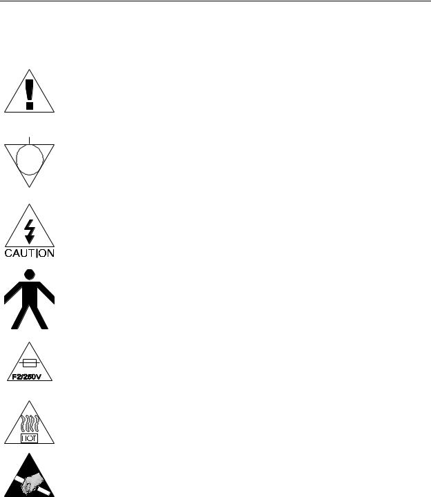
System Symbol Descriptions
Attention. Read Service Manual for Warnings, Precautions, and Instructions for Use.
Potential Equalization Stud
Dangerous Voltage
TYPE B Equipment
Warning. Risk of Fire. Replace Fuses as Marked.
Intense heat may be emitted. Use extreme caution when handling.
ESD Warning. Many of the electronic devises in this equipment are static sensitive.
1-5 LCI-100/200 Service Manual |
Rev. D, 7/30/96 |

6HFWLRQýì *HQHUDOý,QIRUPDWLRQ
1-6 LCI-100/200 Service Manual |
Rev. D, 7/30/96 |

Service
Intent of Manual
The purpose of this manual is to provide Welch Allyn Inc. authorized service representatives with systematic guidelines for preventative maintenance, problem identification, and service of the LCI-100/200 Illumination and Imaging System. We have included the theory of operation, schematic diagrams, simplified drawings, service tips and procedures, to assist a trained service representative with board level repairs. Should you encounter problems that are beyond the scope of this manual, please contact Welch Allyn's Imaging Products Group Service
Department for assistance.
Required Tools for Service
You will need only standard electronic and mechanical tools to perform board level repairs. Test equipment must be in good condition and calibrated regularly. The following commercially available tools are required for the repairs included in this manual.
Antistatic Workstation
DVMS Milli-ohmmeter Fluke Model 77 or equivalent
Oscilloscope (TV triggering)
Vectorscope Tektronics 1745, Tektronics WVR500, or equivalent (for color-related video adjustments only)
Calibrated, NTSC or PAL video monitor, SONY PVM 1350 or equivalent preferably Medical Grade.
Associated Research 411 AI AC Hipot Jr or Equivalent
Hipot Shorting Plug (WT-5736)
40W Soldering Iron
Welch Allyn Tools: These tools can be purchased from Welch Allyn
(Welch Allyn Tool Number appears in parentheses).
Leakage Tester (WT-5515) or Equivalent
LEMO Connector HyPot Test Tool (WT-5756)
Front Panel LEMO Removal Tool (WT-1962)
Final Test Spec P02113
2-1 LCI-100/200 Service Manual |
Rev. D, 7/30/96 |

Section 2 Service
Words of Caution
High Voltage
Use caution when servicing an LCI series system. When servicing the unit, potentially dangerous high voltage levels are exposed. Disconnect the power cord whenever possible to avoid electric shock.
Static Electricity (ESD)
Adhere to standard ESD practices at all times when servicing this equipment. Many of the electronic devices in this equipment are static sensitive, and may suffer catastrophic or latent failure if handled improperly.
Fiber Optics
If it is necessary to handle exposed fiber optic glass, use extreme caution. Unnoticed broken or loose fibers can get in your fingers, hair, and clothing. Avoid contact with eyes or face during and directly after fiber optic contact. Wash hands thoroughly after fiber optic contact.
Finished Parts
Handle all finished parts with care. The finish can be easily scratched or damaged from poor or improper handling.
Heat
Lamps, power supplies, and heat sinks may emit extreme amounts of heat during and after operation. approach and handle these and other potentially hot components with caution.
2-2 LCI-100/200 Service Manual |
Rev. D, 7/30/96 |

6HFWLRQэлэээээ6HUYLFH
Performance Checks
The following performance checks will help you (1) determine whether or not the LCI-100/200 is operating correctly, and (2) isolate a problem, if there is one.
System Set Up
Make sure that the LCI-100/200 is connected as follows:
1.Be sure that power is being provided by the wall outlet. Plug the power cord into the back of the LCI-100/200, and plug in the video monitor. Do not turn the power on.
2.Plug the fiber optic bundle into the light port on the Power Box, and plug the Camera Head cable into the Power Box. The Camera
Head must be plugged in before the Power Box is turned "ON".
The Camera Head should have a C-Mount optical coupler attached.
Attach the Fiber Optic Bundle and Camera Head to an endoscope
(preferably a 10mm diameter laparoscope).
3.Be sure that the video monitor is functioning properly. This may involve connecting a different camera or VCR through the same composite S-video connector.
4.Connect both the S-video and the composite video cables between the LCI-100/200 and the tested video monitor.
5.Turn POWER switch on both the video monitor and the LCI-100/200 to "ON". After 5-10 seconds of warming up, the lamps will produce a steady, white light, which should come through the tip of the laparoscope. The Power LED should be illuminated on the Power
Box, and the Lamp Service LED should not be illuminated. The middle LED in the Picture Brightness panel should be illuminated, and the user should be able to move the LED up or down. A high quality video image should be displayed on the monitor. Do not repeatedly turn the LCI-100/200 On and Off; the lamp needs 1015 seconds to "cool down" between uses.
If these conditions do not occur, see the troubleshooting section.
2-3 LCI-100/200 Service Manual |
Rev. D, 7/30/96 |

6HFWLRQэлэээээ6HUYLFH
Testing the CCD/Video Connections
1.Remove the Camera Head (with Coupler) from the endoscope.
2.Cover the Camera Head with your hand, so that no light gets into CCD.
3.Inspect video monitor. There should be no electronic noise displayed.
4.Wiggle the LEMO connector, and inspect the monitor. There should be no electronic noise.
5.Wiggle the strain relief near the Camera Head and inspect the monitor. There should be no electronic noise.
NOTE: Early units (prior to serial number 100253) may exhibit minor amounts of electronic noise when camera head is covered. This is normal for early units.
Testing the Light Control Functions
1.Reattach the Camera Head (with coupler) to the endoscope. The fiber optic light guide should also be attached.
2.Place your hand 12 inches away from the endoscope tip. Quickly move our hand to 1/2 inch away from the endoscope and observe the monitor. The LCI-100/200 should take about one second to adjust from a bright scene to a normal scene. Repeat the procedure several times.
3.Press the Picture Brightness control to its lowest position, and inspect the monitor. The picture should be darker. Repeat the hand test above. The LCI-100/200 should still be able to adjust to different lighting conditions, although the brightness of the video image will be lower.
4.Press the Picture Brightness control to the second highest position, and inspect the monitor. The picture should appear bright. Repeat the hand test from Step 2. The LCI-100/200 should still be able to adjust to different lighting conditions, although the brightness of the video image will be higher.
5.Press the Picture Brightness control to the highest position. In this position, the mechanical shutter opens up completely, and all light control functions are performed electronically by the SONY autoshutter. Repeat the hand test from Step 2; the electronic autoshutter should take about 2 seconds to adjust from a 12 inch distance to a 1/2 inch distance. This is normal.
6.Return the Picture Brightness control to the middle setting.
2-4 LCI-100/200 Service Manual |
Rev. D, 7/30/96 |

6HFWLRQэлэээээ6HUYLFH
*Testing the Optical Sensor and Shutter
1.While the LCI-100/200 is still powered "ON" remove the fiber optic bundle. the light coming out of the LCI unit should fade. The
Picture Brightness control switches should be de-activated.
2.Plug the fiber optic bundle back into the LCI-100/200. The sensor should be activated and light should come out the tip of the fiber optic bundle.
Examining the Fiber Optic Bundle
All fiber optic bundles degrade over time. As fibers break, less light is conducted from the lamp to the scope being used. As a result, a worm fiber optic bundle can cause the video picture to appear too dark. Welch Allyn recommends that a need fiber optic bundle be purchased every 6- 12 months (which is about the same cycle as the lamp).
1.Remove the fiber optic bundle from the LCI-100/200.
2.Hold one tip of the bundle up to an overhead light, and examine the other tip of the bundle. If more than 20% of the individual fibers appear broken (i.e.: more than 20% of the fiber bundle is dark), then the bundle should be replaced.
3.Replace only with Welch Allyn Part Number VA295.
Calibrations
Routine electrical calibration of the LCI-100/200 is not required. All electrical parameters are factory set.
Routine calibration of video monitors is highly recommended. Refer to your video monitor service manual for instructions on calibration and video alignment.
2-5 LCI-100/200 Service Manual |
Rev. D, 7/30/96 |
6HFWLRQэлэээээ6HUYLFH
2-6 LCI-100/200 Service Manual |
Rev. D, 7/30/96 |
Loading...