


 Loading...
Welch Allyn Spot Vital Signs
S S a mm g
DIA a mm g
SpO2
min
Spot Vital Signs
Service Manual

ii |
Welch Allyn Spot Vital Signs |
Copyright 2012 Welch Allyn. All rights are reserved. To support the intended use of the product described in this publication, the purchaser of the product is permitted to copy this publication, for internal distribution only, from the media provided by Welch Allyn. No other use, reproduction, or distribution of the publication, or any part of it, is permitted without written permission from Welch Allyn.
Welch Allyn assumes no responsibility for any injury to anyone, or for any illegal or improper use of the product, that may result from failure to use this product in accordance with the instructions, cautions, warnings, or statement of intended use published in this manual.
Welch Allyn, Spot Vital Signs, SureBP Technology, and SureTemp are registered trademarks of Welch Allyn.
LNCS is a trademark of, and SET, LNOP, and Masimo are registered trademarks of, Masimo Corporation. Possession or purchase of a Masimo SpO2-equipped device does not convey any express or implied license to use the device with unauthorized sensors or cables which would, alone or in combination with this device, fall within the scope of one or more of the patents relating to this device.
Nellcor and Oxi-Max are registered trademarks of Nellcor Puritan Bennett Inc.
Software in this product is Copyright Welch Allyn or its vendors. All rights are reserved. The software is protected by United States of America copyright laws and international treaty provisions applicable worldwide. Under such laws, the licensee is entitled to use the copy of the software incorporated with this instrument as intended in the operation of the product in which it is embedded. The software may not be copied, decompiled, reverse-engineered, disassembled, or otherwise reduced to human-perceivable form. This is not a sale of the software or any copy of the software; all right, title, and ownership of the software remain with Welch Allyn or its vendors.
For information about any Welch Allyn product, call Welch Allyn Technical Support:
USA |
+1 800 289 2501 |
Australia |
+61 |
2 9638 3000 |
|
Canada |
+1 800 561 8797 |
China |
+86 |
21 6327 9631 |
|
European Call Center |
+353 46 90 67790 |
France |
+33 |
1 55 69 58 49 |
|
Germany |
+49 |
695 098 5132 |
Japan |
+81 |
42 703 6084 |
Latin America |
+1 305 669 9003 |
Netherlands |
+31 |
202 061 360 |
|
Singapore |
+65 |
6419 8100 |
South Africa |
+27 |
11 777 7555 |
United Kingdom |
+44 |
207 365 6780 |
Sweden |
+46 |
85 853 6551 |
Reorder No. 4200-89E
Manual Material No. 718448 Ver A
Welch Allyn |
|
|
Regulatory Affairs Representative |
4341 State Street Road |
EC |
REP |
Welch Allyn Limited |
Skaneateles Falls, NY 13153 USA |
|
|
Navan Business Park |
|
|
|
Dublin Road |
|
|
|
Navan, County Meath, Republic of Ireland |
Printed in USA

Service Manual |
iii |
Revision Information
Date |
Revision |
Description |
Originator |
Approval |
|
|
|
|
|
3/31/01 |
A |
Introduction of Service Manual |
JDB |
JDB |
|
|
|
|
|
12/17/01 |
B |
Correction made to Section 1 regarding temperature accuracy, |
JDB |
JDB |
|
|
Section 2 regarding part numbers, Section 3 regarding error |
|
|
|
|
codes, and updates to the drawings |
|
|
|
|
|
|
|
9/12/02 |
C |
Added New PCB layout and schematic for Spot Extensions. |
JDB |
JDB |
|
|
Added tool SRC-MAX to tool list in Section 2.3. Removed old PCB |
|
|
|
|
and Old SpO2 PCB and replaced with new Main PCB and New |
|
|
|
|
SpO2 PCB in section 2.4. Changed section 4.7 to cover both Spot |
|
|
|
|
and Spot Extensions SpO2 PCB removal and replacement. |
|
|
|
|
Changed section 5.8 to cover both Spot and Spot Extension SpO2 |
|
|
|
|
testing. General Spelling and grammar clean up. |
|
|
|
|
|
|
|
02/02/03 |
D |
Arden document release to SKF. Updated USA Service Center |
JDB |
DLK |
|
|
contact information. |
|
|
|
|
|
|
|
05/01/03 |
E |
Correction to tools required for service. Corrected General |
DLK |
DLK |
|
|
Information phone numbers. |
|
|
|
|
|
|
|
09/16/03 |
F |
Updates repair BOM. Updated Accessories. Re-formated manual |
DLK |
DLK |
|
|
to meet Welch Allyn service manual work instructions. |
|
|
|
|
|
|
|
12/12/03 |
G |
Correction to page numbering and to voltage calibrations. Re- |
DLK |
RJS |
|
|
formatted all systems of measurement to meet NIST Standards. |
|
|
|
|
Reformatted Appendix E. Corrected grammar and punctuation. |
|
|
|
|
Revised service and support details in Section 1. Removed |
|
|
|
|
schematics. |
|
|
|
|
|
|
|
3/9/06 |
H |
Removed references to Nellcor motion tolerance. |
AMJ |
JPK |
|
|
|
|
|
3/21/07 |
J |
SAP new version glitch |
AMJ |
FL |
|
|
|
|
|
3/21/07 |
K |
Update section on Setting the Date and Time. Include testing and |
AMJ |
FL |
|
|
disassembly/assembly for the Masimo SpO2 feature and |
|
|
|
|
updated repair parts lists. |
|
|
|
|
|
|
|
2010/11/05 |
L |
Changed part number for SPOT Repair Tool SW CD from 130S57E |
KMR |
NEA |
|
|
to 716948 on pages 39 and 52 . Updated copyright page with |
|
|
|
|
latest service phone numbers and combined Title pages and |
|
|
|
|
Front cover pages. |
|
|
|
|
|
|
|
2012/04/26 |
A |
New Material Number taken out 718448. CE mark removal |
KMR |
GB |
|
|
|
|
|
Drawings and/or illustrations and/or part numbers in this document are for reference only. For the most current revision call the Welch Allyn Customer Service phone number (see page ii).
iv |
Welch Allyn Spot Vital Signs |

v
Contents
1 - Introduction . . . . . . . . . . . . . . . . . . . . . . . . . . . . . . . . . . . . . . . . . . . . . 1
Warnings and cautions . . . . . . . . . . . . . . . . . . . . . . . . . . . . . . . . . . . . . . . . . . . . . 1 General warnings . . . . . . . . . . . . . . . . . . . . . . . . . . . . . . . . . . . . . . . . . . . . . . 1 Blood pressure warnings . . . . . . . . . . . . . . . . . . . . . . . . . . . . . . . . . . . . . . . . 3 SpO2 warnings . . . . . . . . . . . . . . . . . . . . . . . . . . . . . . . . . . . . . . . . . . . . . . . . 4 Temperature warnings . . . . . . . . . . . . . . . . . . . . . . . . . . . . . . . . . . . . . . . . . . 5 IR communications port warnings . . . . . . . . . . . . . . . . . . . . . . . . . . . . . . . . . 5 General cautions . . . . . . . . . . . . . . . . . . . . . . . . . . . . . . . . . . . . . . . . . . . . . . 5 Blood pressure cautions. . . . . . . . . . . . . . . . . . . . . . . . . . . . . . . . . . . . . . . . . 6 SpO2 cautions . . . . . . . . . . . . . . . . . . . . . . . . . . . . . . . . . . . . . . . . . . . . . . . . 6 Temperature cautions . . . . . . . . . . . . . . . . . . . . . . . . . . . . . . . . . . . . . . . . . . 6
Electrostatic discharge (ESD) . . . . . . . . . . . . . . . . . . . . . . . . . . . . . . . . . . . . . . . . 7 Symbols . . . . . . . . . . . . . . . . . . . . . . . . . . . . . . . . . . . . . . . . . . . . . . . . . . . . . . . . 8 Safety symbols. . . . . . . . . . . . . . . . . . . . . . . . . . . . . . . . . . . . . . . . . . . . . . . . 8 Agency symbols. . . . . . . . . . . . . . . . . . . . . . . . . . . . . . . . . . . . . . . . . . . . . . . 8
2 - Overview . . . . . . . . . . . . . . . . . . . . . . . . . . . . . . . . . . . . . . . . . . . . . . . 9
Purpose and scope . . . . . . . . . . . . . . . . . . . . . . . . . . . . . . . . . . . . . . . . . . . . . . . . 9 Other applicable documents. . . . . . . . . . . . . . . . . . . . . . . . . . . . . . . . . . . . . . . . . 9 Contents checklist . . . . . . . . . . . . . . . . . . . . . . . . . . . . . . . . . . . . . . . . . . . . . . . 10 Possible attachments . . . . . . . . . . . . . . . . . . . . . . . . . . . . . . . . . . . . . . . . . . . . . 10 Service . . . . . . . . . . . . . . . . . . . . . . . . . . . . . . . . . . . . . . . . . . . . . . . . . . . . . . . . 11
Technical assistance . . . . . . . . . . . . . . . . . . . . . . . . . . . . . . . . . . . . . . . . . . 11 Field replacement units . . . . . . . . . . . . . . . . . . . . . . . . . . . . . . . . . . . . . . . . 11 Service loaners. . . . . . . . . . . . . . . . . . . . . . . . . . . . . . . . . . . . . . . . . . . . . . . 11 Service intervals . . . . . . . . . . . . . . . . . . . . . . . . . . . . . . . . . . . . . . . . . . . . . . . . . 12 Spot Vital Signs configurations . . . . . . . . . . . . . . . . . . . . . . . . . . . . . . . . . . . . . . 12 Controls . . . . . . . . . . . . . . . . . . . . . . . . . . . . . . . . . . . . . . . . . . . . . . . . . . . . . . . 13 LCD (liquid crystal display) . . . . . . . . . . . . . . . . . . . . . . . . . . . . . . . . . . . . . . . . . 15 Connections . . . . . . . . . . . . . . . . . . . . . . . . . . . . . . . . . . . . . . . . . . . . . . . . . . . . 16 Blood pressure hose and cuff connections . . . . . . . . . . . . . . . . . . . . . . . . . . . . 17 Temperature probe connection . . . . . . . . . . . . . . . . . . . . . . . . . . . . . . . . . . . . . 17 SpO2 sensor. . . . . . . . . . . . . . . . . . . . . . . . . . . . . . . . . . . . . . . . . . . . . . . . . 17 Quick reference card . . . . . . . . . . . . . . . . . . . . . . . . . . . . . . . . . . . . . . . . . . 17 DCpower connection . . . . . . . . . . . . . . . . . . . . . . . . . . . . . . . . . . . . . . . . . . 18 Charging the battery . . . . . . . . . . . . . . . . . . . . . . . . . . . . . . . . . . . . . . . . . . . . . . 18 Standby mode. . . . . . . . . . . . . . . . . . . . . . . . . . . . . . . . . . . . . . . . . . . . . . . . . . . 18
vi |
Contents |
Welch Allyn Spot Vital Signs |
3 - Functional overview . . . . . . . . . . . . . . . . . . . . . . . . . . . . . . . . . . . . . 19
Power on/off and system check procedure . . . . . . . . . . . . . . . . . . . . . . . . . . . . 19 Internal configuration mode . . . . . . . . . . . . . . . . . . . . . . . . . . . . . . . . . . . . . . . . 20 Functional verification . . . . . . . . . . . . . . . . . . . . . . . . . . . . . . . . . . . . . . . . . . . . . 21 Temperature functional check . . . . . . . . . . . . . . . . . . . . . . . . . . . . . . . . . . . 22 SpO2 functional check . . . . . . . . . . . . . . . . . . . . . . . . . . . . . . . . . . . . . . . . . 24
4 - Calibration . . . . . . . . . . . . . . . . . . . . . . . . . . . . . . . . . . . . . . . . . . . . . 25
Connections . . . . . . . . . . . . . . . . . . . . . . . . . . . . . . . . . . . . . . . . . . . . . . . . . . . . 25 Voltage calibration. . . . . . . . . . . . . . . . . . . . . . . . . . . . . . . . . . . . . . . . . . . . . . . . 27 Blood pressure calibration . . . . . . . . . . . . . . . . . . . . . . . . . . . . . . . . . . . . . . . . . 27 Date/time set . . . . . . . . . . . . . . . . . . . . . . . . . . . . . . . . . . . . . . . . . . . . . . . . . . . 28
5 - Troubleshooting . . . . . . . . . . . . . . . . . . . . . . . . . . . . . . . . . . . . . . . . 29
Error codes . . . . . . . . . . . . . . . . . . . . . . . . . . . . . . . . . . . . . . . . . . . . . . . . . . . . . 29 Causes and corrective action . . . . . . . . . . . . . . . . . . . . . . . . . . . . . . . . . . . . . . . 30 Battery voltage check . . . . . . . . . . . . . . . . . . . . . . . . . . . . . . . . . . . . . . . . . . . . . 33 Window display check . . . . . . . . . . . . . . . . . . . . . . . . . . . . . . . . . . . . . . . . . . . . 33 Blood pressure calibration check . . . . . . . . . . . . . . . . . . . . . . . . . . . . . . . . . . . . 33
Temperature functional check . . . . . . . . . . . . . . . . . . . . . . . . . . . . . . . . . . . 34 Masimo SpO2 functional check . . . . . . . . . . . . . . . . . . . . . . . . . . . . . . . . . . 34 Nellcor SpO2 functional check . . . . . . . . . . . . . . . . . . . . . . . . . . . . . . . . . . . 34 Communication option check. . . . . . . . . . . . . . . . . . . . . . . . . . . . . . . . . . . . 34 Functional testing procedures . . . . . . . . . . . . . . . . . . . . . . . . . . . . . . . . . . . . . . 34 Current test. . . . . . . . . . . . . . . . . . . . . . . . . . . . . . . . . . . . . . . . . . . . . . . . . . . . . 35 Noise levels . . . . . . . . . . . . . . . . . . . . . . . . . . . . . . . . . . . . . . . . . . . . . . . . . . . . 35 Button test . . . . . . . . . . . . . . . . . . . . . . . . . . . . . . . . . . . . . . . . . . . . . . . . . . . . . 35 Interface test . . . . . . . . . . . . . . . . . . . . . . . . . . . . . . . . . . . . . . . . . . . . . . . . . . . 36 Print quality . . . . . . . . . . . . . . . . . . . . . . . . . . . . . . . . . . . . . . . . . . . . . . . . . . . . . 36 Pneumatic tests . . . . . . . . . . . . . . . . . . . . . . . . . . . . . . . . . . . . . . . . . . . . . . . . . 37 Fail safe (over pressure) test . . . . . . . . . . . . . . . . . . . . . . . . . . . . . . . . . . . . . . . 37 Service work checklist . . . . . . . . . . . . . . . . . . . . . . . . . . . . . . . . . . . . . . . . . . . . 38
6 - Disassembly and repair . . . . . . . . . . . . . . . . . . . . . . . . . . . . . . . . . . 39
Battery disassembly . . . . . . . . . . . . . . . . . . . . . . . . . . . . . . . . . . . . . . . . . . . . . . 40 Temperature disassembly . . . . . . . . . . . . . . . . . . . . . . . . . . . . . . . . . . . . . . . . . 41 Front housing and key pad disassembly. . . . . . . . . . . . . . . . . . . . . . . . . . . . . . . 42 LCD disassembly . . . . . . . . . . . . . . . . . . . . . . . . . . . . . . . . . . . . . . . . . . . . . . . . 42 Power and battery cable disassembly . . . . . . . . . . . . . . . . . . . . . . . . . . . . . . . . 43 Main printed circuit board assembly. . . . . . . . . . . . . . . . . . . . . . . . . . . . . . . . . . 44 SpO2 circuit board disassembly . . . . . . . . . . . . . . . . . . . . . . . . . . . . . . . . . . . . . 45
Masimo board . . . . . . . . . . . . . . . . . . . . . . . . . . . . . . . . . . . . . . . . . . . . . . . 45
Nellcor board . . . . . . . . . . . . . . . . . . . . . . . . . . . . . . . . . . . . . . . . . . . . . . . . 47
Pump and valve disassembly . . . . . . . . . . . . . . . . . . . . . . . . . . . . . . . . . . . . . . . 48
7 - Technical overview . . . . . . . . . . . . . . . . . . . . . . . . . . . . . . . . . . . . . . 51
System description . . . . . . . . . . . . . . . . . . . . . . . . . . . . . . . . . . . . . . . . . . . . . . . 51 Battery /charge system . . . . . . . . . . . . . . . . . . . . . . . . . . . . . . . . . . . . . . . . 51
Service Manual |
Contents |
vii |
Main CPU power supply. . . . . . . . . . . . . . . . . . . . . . . . . . . . . . . . . . . . . . . . 51 Clock/calendar power . . . . . . . . . . . . . . . . . . . . . . . . . . . . . . . . . . . . . . . . . . 51 Mod B NIBP power . . . . . . . . . . . . . . . . . . . . . . . . . . . . . . . . . . . . . . . . . . . 52 Thermometer power . . . . . . . . . . . . . . . . . . . . . . . . . . . . . . . . . . . . . . . . . . 52 SpO2 power . . . . . . . . . . . . . . . . . . . . . . . . . . . . . . . . . . . . . . . . . . . . . . . . . 52 LCD power . . . . . . . . . . . . . . . . . . . . . . . . . . . . . . . . . . . . . . . . . . . . . . . . . . 52 Communications . . . . . . . . . . . . . . . . . . . . . . . . . . . . . . . . . . . . . . . . . . . . . 52
Interconnect diagram . . . . . . . . . . . . . . . . . . . . . . . . . . . . . . . . . . . . . . . . . . . . . 53
8 - Field replaceable units . . . . . . . . . . . . . . . . . . . . . . . . . . . . . . . . . . . 55 9 - Specifications . . . . . . . . . . . . . . . . . . . . . . . . . . . . . . . . . . . . . . . . . . 59
Patient population . . . . . . . . . . . . . . . . . . . . . . . . . . . . . . . . . . . . . . . . . . . . . . . . 59 Blood pressure . . . . . . . . . . . . . . . . . . . . . . . . . . . . . . . . . . . . . . . . . . . . . . . . . . 59 Temperature . . . . . . . . . . . . . . . . . . . . . . . . . . . . . . . . . . . . . . . . . . . . . . . . . . . . 59 Pulse pximetry . . . . . . . . . . . . . . . . . . . . . . . . . . . . . . . . . . . . . . . . . . . . . . . . . . 60 Masimo sensor accuracy guide . . . . . . . . . . . . . . . . . . . . . . . . . . . . . . . . . . 60 Masimo patents . . . . . . . . . . . . . . . . . . . . . . . . . . . . . . . . . . . . . . . . . . . . . . 60 Nellcor® sensor accuracy guide. . . . . . . . . . . . . . . . . . . . . . . . . . . . . . . . . . 61 Nellcor patents . . . . . . . . . . . . . . . . . . . . . . . . . . . . . . . . . . . . . . . . . . . . . . . 62 Mechanical . . . . . . . . . . . . . . . . . . . . . . . . . . . . . . . . . . . . . . . . . . . . . . . . . . . . . 62 Electrical . . . . . . . . . . . . . . . . . . . . . . . . . . . . . . . . . . . . . . . . . . . . . . . . . . . . . . . 62 Environmental. . . . . . . . . . . . . . . . . . . . . . . . . . . . . . . . . . . . . . . . . . . . . . . . . . . 62 Guidance and manufacturer’s declaration . . . . . . . . . . . . . . . . . . . . . . . . . . . . . 63 Emissions and immunity information . . . . . . . . . . . . . . . . . . . . . . . . . . . . . . 63 Patents . . . . . . . . . . . . . . . . . . . . . . . . . . . . . . . . . . . . . . . . . . . . . . . . . . . . . . . . 66 Identification label and serial numbering system . . . . . . . . . . . . . . . . . . . . . . . . 67 Firmware identification . . . . . . . . . . . . . . . . . . . . . . . . . . . . . . . . . . . . . . . . . . . . 67
10 - Maintenance . . . . . . . . . . . . . . . . . . . . . . . . . . . . . . . . . . . . . . . . . . 69
Cleaning . . . . . . . . . . . . . . . . . . . . . . . . . . . . . . . . . . . . . . . . . . . . . . . . . . . . . . . 69 Spot Vital Signs . . . . . . . . . . . . . . . . . . . . . . . . . . . . . . . . . . . . . . . . . . . . . . 69 Blood pressure cuff . . . . . . . . . . . . . . . . . . . . . . . . . . . . . . . . . . . . . . . . . . . 69 Cables and pressure hose . . . . . . . . . . . . . . . . . . . . . . . . . . . . . . . . . . . . . . 69 Temperature probe. . . . . . . . . . . . . . . . . . . . . . . . . . . . . . . . . . . . . . . . . . . . 70 SpO2 sensor . . . . . . . . . . . . . . . . . . . . . . . . . . . . . . . . . . . . . . . . . . . . . . . . . 70
Battery removal and replacement. . . . . . . . . . . . . . . . . . . . . . . . . . . . . . . . . . . . 70 Masimo SpO2 calibration check . . . . . . . . . . . . . . . . . . . . . . . . . . . . . . . . . . . . . 71 Nellcor SpO2 functional check . . . . . . . . . . . . . . . . . . . . . . . . . . . . . . . . . . . . . . 71 SpO2 accessory disposal . . . . . . . . . . . . . . . . . . . . . . . . . . . . . . . . . . . . . . . . . . 71 Temperature calibration check . . . . . . . . . . . . . . . . . . . . . . . . . . . . . . . . . . . . . . 71
A - Repair test specifications . . . . . . . . . . . . . . . . . . . . . . . . . . . . . . . . . 73
General unit test . . . . . . . . . . . . . . . . . . . . . . . . . . . . . . . . . . . . . . . . . . . . . . . . . 73 A-D noise test . . . . . . . . . . . . . . . . . . . . . . . . . . . . . . . . . . . . . . . . . . . . . . . 73 Leak test . . . . . . . . . . . . . . . . . . . . . . . . . . . . . . . . . . . . . . . . . . . . . . . . . . . 73 Inflation test . . . . . . . . . . . . . . . . . . . . . . . . . . . . . . . . . . . . . . . . . . . . . . . . . 73 Dump test . . . . . . . . . . . . . . . . . . . . . . . . . . . . . . . . . . . . . . . . . . . . . . . . . . 73
viii |
Contents |
Welch Allyn Spot Vital Signs |
Pneumatic calibration . . . . . . . . . . . . . . . . . . . . . . . . . . . . . . . . . . . . . . . . . . 74 Pneumatic accuracy test . . . . . . . . . . . . . . . . . . . . . . . . . . . . . . . . . . . . . . . 74 Valve control test . . . . . . . . . . . . . . . . . . . . . . . . . . . . . . . . . . . . . . . . . . . . . 74 Voltage calibration . . . . . . . . . . . . . . . . . . . . . . . . . . . . . . . . . . . . . . . . . . . . 74 Blank mode current test. . . . . . . . . . . . . . . . . . . . . . . . . . . . . . . . . . . . . . . . 74 Back light (Idle) current test . . . . . . . . . . . . . . . . . . . . . . . . . . . . . . . . . . . . . 75 Valve/pump mode current test. . . . . . . . . . . . . . . . . . . . . . . . . . . . . . . . . . . 75 Interface test . . . . . . . . . . . . . . . . . . . . . . . . . . . . . . . . . . . . . . . . . . . . . . . . 75
Temperature option requirements . . . . . . . . . . . . . . . . . . . . . . . . . . . . . . . . . . . 75 Accuracy test . . . . . . . . . . . . . . . . . . . . . . . . . . . . . . . . . . . . . . . . . . . . . . . . 75 Temperature probe test . . . . . . . . . . . . . . . . . . . . . . . . . . . . . . . . . . . . . . . . 75 SpO2 option requirements . . . . . . . . . . . . . . . . . . . . . . . . . . . . . . . . . . . . . . . . . 75 SpO2 functional test . . . . . . . . . . . . . . . . . . . . . . . . . . . . . . . . . . . . . . . . . . . 75 SpO2 mode current test . . . . . . . . . . . . . . . . . . . . . . . . . . . . . . . . . . . . . . . . 75 Fail safe test . . . . . . . . . . . . . . . . . . . . . . . . . . . . . . . . . . . . . . . . . . . . . . . . . . . . 76 Over pressure test . . . . . . . . . . . . . . . . . . . . . . . . . . . . . . . . . . . . . . . . . . . . 76 Over 15 mmHg . . . . . . . . . . . . . . . . . . . . . . . . . . . . . . . . . . . . . . . . . . . . . . 76
B - Supplies and Accessories . . . . . . . . . . . . . . . . . . . . . . . . . . . . . . . . 77
Latex-free blood pressure. . . . . . . . . . . . . . . . . . . . . . . . . . . . . . . . . . . . . . . . . . 77 Pulse oximetry accessories and supplies . . . . . . . . . . . . . . . . . . . . . . . . . . . . . . 78 Masimo . . . . . . . . . . . . . . . . . . . . . . . . . . . . . . . . . . . . . . . . . . . . . . . . . . . . 78 Nellcor . . . . . . . . . . . . . . . . . . . . . . . . . . . . . . . . . . . . . . . . . . . . . . . . . . . . . 79 Temperature . . . . . . . . . . . . . . . . . . . . . . . . . . . . . . . . . . . . . . . . . . . . . . . . . . . . 80 Mounting . . . . . . . . . . . . . . . . . . . . . . . . . . . . . . . . . . . . . . . . . . . . . . . . . . . . . . 80 Extended warranty . . . . . . . . . . . . . . . . . . . . . . . . . . . . . . . . . . . . . . . . . . . . . . . 80 Miscellaneous. . . . . . . . . . . . . . . . . . . . . . . . . . . . . . . . . . . . . . . . . . . . . . . . . . . 81
C - Miscellaneous Mounting Accessories. . . . . . . . . . . . . . . . . . . . . . . 83
Wall mount kit (REF 4200-62) . . . . . . . . . . . . . . . . . . . . . . . . . . . . . . . . . . . . . . . 83 Mobile stand kit (REF 4200-60). . . . . . . . . . . . . . . . . . . . . . . . . . . . . . . . . . . . . . 84 IV pole mount accessory (REF 4200-64). . . . . . . . . . . . . . . . . . . . . . . . . . . . . . . 85 Anti-theft kit (REF 4200-70) . . . . . . . . . . . . . . . . . . . . . . . . . . . . . . . . . . . . . . . . 86 Transformer mounting plate accessory (REF 4200-75). . . . . . . . . . . . . . . . . . . . 87 IR dongle mounting accessory (REF 4200-170) . . . . . . . . . . . . . . . . . . . . . . . . . 88
Warranty . . . . . . . . . . . . . . . . . . . . . . . . . . . . . . . . . . . . . . . . . . . . . . . . . 89
Spot Vital Signs. . . . . . . . . . . . . . . . . . . . . . . . . . . . . . . . . . . . . . . . . . . . . . . . . . 89
Accessories . . . . . . . . . . . . . . . . . . . . . . . . . . . . . . . . . . . . . . . . . . . . . . . . . . . . 89

1
1 Introduction
Welch Allyn has updated the Spot Vital Signs from its original configuration; offering a Pressure Preset option (Version 2, page 14) instead of a Print option (Version 1, page 13). In addition, some Version 2 configurations offer Masimo SpO2 technology.
Table 1. Version comparison
Function/Appearance |
Version 1 |
Version 2 |
|
(serial number less than |
(serial number 200705000 |
|
200705000) |
and above) |
|
|
|
Available option |
Pressure Preset |
|
|
|
|
Available SpO2 capability |
Nellcor |
Masimo or Nellcor |
Bezel and switch array color |
Black bezel/multi-colored |
Blue |
|
switch array |
|
|
|
|
Warnings and cautions
Familiarize all operating personnel with the general safety information in this summary. Specific warnings and cautions are also found throughout this manual. Such specific warnings and cautions may not appear here in this summary.
General warnings
A warning statement in this manual identifies a condition or practice, which if not corrected or discontinued immediately, could lead to patient injury, illness, or death.
WARNING The Welch Allyn Spot Vital Signs is designed for use by medical clinicians. Although this manual may illustrate medical spot check techniques, only a trained clinician who knows how to take and interpret a patient’s vital signs should use this system.
WARNING The information in this manual is a comprehensive guide to the operation of the Welch Allyn Spot Vital Signs. To achieve satisfactory results, you should read the manual thoroughly before attempting to use the device.
WARNING Spot Vital Signs is not intended to take measurements on neonatal patients. The AAMI SP10:1992 standard defines neonates as children 28 days or less of age if born at term (37 weeks gestation or more); otherwise up to 44 gestational weeks.
WARNING The Welch Allyn Spot Vital Signs is not defibrillator proof.

2 |
Introduction |
Welch Allyn Spot Vital Signs |
WARNING The Welch Allyn Spot Vital Signs is not intended for continuous monitoring. Do not leave the device unattended while taking measurements on a patient.
WARNING To ensure patient safety, use only accessories and supplies (i.e., blood pressure cuffs, hoses, temperature probes, SpO2 sensors, etc.) recommended for or supplied with Spot Vital Signs. Using unapproved accessories with Spot Vital Signs can affect patient and/or operator safety.
WARNING This device is not suitable for use in the presence of a flammable anesthetic mixture with air or oxygen or nitrous oxide. An explosion may result.
WARNING Avoid compression of the blood pressure cuff tubing or pressure hose of the Welch Allyn Spot Vital Signs. Compression of the cuff tubing or pressure hose may cause system errors to occur in the device.
WARNING Care should be taken to prevent water or other fluid from entering any connectors on the device. Should this occur, the connectors should be dried with warm air. All operating functions should then be checked for proper operation.
WARNING Any Spot Vital Signs which has been dropped or damaged should be checked by qualified service personnel to ensure proper operation prior to use. Do not use the Welch Allyn Spot Vital Signs if you notice any signs of damage.
Contact the Welch Allyn Customer Service Department for assistance.
WARNING Every three months, inspect the temperature probe, SpO2 cord, and accessories for fraying or other damage. Replace as necessary.
WARNING There are no user-serviceable parts inside the device other than battery replacement. Refer Spot Vital Signs to the Authorized Service Center.
WARNING The Spot Vital Signs should not be used on patients who are linked to heart/lung machines.
WARNING The Spot Vital Signs does not operate effectively on patients who are experiencing convulsions or tremors.
WARNING This device complies with current required standards for electromagnetic interference and should not present problems to other equipment or be affected by other devices. As a precaution, avoid using this device in close proximity to other equipment.
WARNING This device is not intended for hand-held use during operation.
WARNING Welch Allyn recommends leaving the battery in the device, regardless if the device is not used for long periods of time, since there is no hazard of leaving the battery in the device.
WARNING Do not autoclave.
WARNING Welch Allyn is not responsible for the integrity of any mounting installation. Welch Allyn recommends that the customer contact their Biomedical Engineering Department or maintenance service to ensure professional installation for safety and reliability of any mounting accessory.
Service Manual |
Introduction |
3 |
Blood pressure warnings
WARNING To ensure pediatric blood pressure accuracy and safety, the Welch Allyn Child Print Cuff (5200-03), the Welch Allyn Small Child Durable One-Piece Cuff (5082-203-3), and the Welch Allyn Small Child Disposable One-Piece Cuff (5082-93-3) are the smallest cuffs allowed for use with young children and infants. The circumference of the child’s arm must fit within the range markings on the cuff.
WARNING You may experience inaccurate blood pressure measurements if blood pressure cuffs and/or hoses other than those provided by Welch Allyn for the Spot Vital Signs are used.
WARNING Patients who are experiencing moderate to severe arrhythmias may give inaccurate blood pressure measurements.
WARNING When several blood pressure measurements are taken on the same patient, it is recommended that the blood pressure cuff site and extremity are checked regularly for possible ischemia, purpura, and/or neuropathy.
WARNING Do not change the connector(s) on the blood pressure cuff tubing of this device to luer type. Luer type connectors are commonly used in intravenous infusion systems. Using the luer connectors on blood pressure cuff tubing creates the risk that the blood pressure tubing could be mistakenly connected to a patient's intravenous line, resulting in the introduction of air into the patient's circulatory system.

4 |
Introduction |
Welch Allyn Spot Vital Signs |
SpO2 warnings
WARNING Only use Spot Vital Signs with Masimo or Nellcor SpO2 option with Masimo or Nellcor brand sensors and accessories, respectively. Using the wrong or unapproved sensors or cables may cause improper performance.
WARNING The SpO2 sensors and extension cables are intended for use only for pulse oximetry measurements. Do not attempt to connect these cables to a PC or any similar device.
WARNING Before use, carefully read the sensor’s directions for use, including all warnings, cautions, and instructions.
WARNING Do not use a damaged sensor or SpO2 cable. Do not use a sensor with exposed optical components.
WARNING Tissue damage can be caused by incorrect application or duration of use of an SpO2 sensor. Inspect the sensor site as directed in the sensor’s Directions for Use.
WARNING Do not use the sensors during magnetic resonance imaging (MRI) scanning. Induced current could potentially cause burns. The pulse oximeter may affect the MRI image, and the MRI unit may affect the accuracy of the pulse oximetry measurements.
WARNING Certain ambient environmental conditions, sensor application errors, and certain patient conditions may affect SpO2 readings and pulse signal.
WARNING Do not immerse the sensor or patient cables in water, solvents, or cleaning solutions (the sensors and connections are not waterproof). Do not use irradiation, steam, or ethylene oxide for sterilization.
WARNING Do not use the SpO2 cable or power cord to lift the unit because the cable or cord could disconnect from the unit, causing the unit to drop on the patient.
WARNING The SpO2 in the Welch Allyn Spot Vital signs is not intended for use as an apnea monitor.
WARNING Consider the SpO2 an early warning device. As a trend toward patient deoxygenation is indicated, use laboratory instruments to analyze blood samples to completely understand the patient’s condition.

Service Manual |
Introduction |
5 |
Temperature warnings
WARNING Single-use, disposable probe covers, available from Welch Allyn, limit patient cross-contamination. The use of any other probe cover or the failure to use a probe cover may produce temperature errors and is specifically not recommended.
WARNING Use only oral probes (blue cap) for taking oral and axillary temperatures. Use only rectal probes (red cap) for taking rectal temperatures. The use of the wrong probe may produce temperature errors.
WARNING Do not allow the tip of the temperature probe to come into contact with any heat source (e.g., hands or fingers) prior to taking a temperature measurement. If this occurs, discard the probe cover and start the temperature determination again.
WARNING Long-term continuous monitoring beyond three to five minutes is not recommended in any mode.
IR communications port warnings
WARNING The Welch Allyn Spot Vital Signs contains an infrared communications port for isolated communications with external devices. The port is located on the side of the device to preclude direct eye contact on a continual basis when viewing the display. As a precaution, do not look directly into the infrared port during operation.
General cautions
A caution statement in this manual identifies a condition or practice, which if not corrected or discontinued immediately, could lead to equipment failure, equipment damage, or data loss.
Caution If the accuracy of any measurement is in question, check the patient's vital sign(s) by an alternate method, then check to make sure the device is functioning properly.
Caution Ensure the device is placed on a secure surface or use one of the optional mounting accessories.
Caution Do not place fluids on the device.

6 |
Introduction |
Welch Allyn Spot Vital Signs |
Blood pressure cautions
Caution Extremity and blood pressure cuff motion should be minimized during blood pressure determinations.
Caution If the blood pressure cuff is not at heart level, the difference in reading due to the hydrostatic effect should be noted. The value of 1.80 mmHg must be added to the displayed reading for every inch (2.5 cm) above heart level. The value of 1.80 mmHg must be subtracted from the displayed reading for every inch (2.5 cm) below heart level.
Caution Proper blood pressure cuff size and placement is essential to the accuracy of the blood pressure determination.
Caution When measuring blood pressure on children younger than 3 years of age, it is recommended that the Pressure Preset (initial inflation pressure) be set at 160 mmHg or lower.
SpO2 cautions
Caution The pulse oximeter is calibrated to determine the percentage of arterial oxygen saturation of functional hemoglobin. Significant levels of dysfunctional hemoglobin such as carboxyhemoglobin or methemoglobin may affect the accuracy of the measurement.
Caution Physiological conditions, medical procedures, or external agents that may interfere with the pulse oximeter’s ability to detect and display measurements include dysfunctional hemoglobin, arterial dyes, low perfusion, dark pigment, and externally applied coloring agents such as nail polish, dye, or pigmented cream.
Caution Some sensors may not be appropriate for a particular patient. If at least 15 seconds of perfusion pulses cannot be observed for a given sensor, change sensor location or sensor type for perfusion to resume.
Caution When selecting a sensor, consider the patient’s weight and activity level, the adequacy of perfusion, the available sensor sites, the need for sterility, and the anticipated duration of monitoring.
Temperature cautions
Caution The Welch Allyn Spot Vital Signs is FDA cleared to measure the axillary temperature in Normal Mode for children under the age of 4. Normal Mode axillary temperatures may not be accurate on older children or adults. THE WELCH ALLYN SPOT VITAL SIGNS IS NOT INTENDED TO BE USED ON NEONATAL PATIENTS.
Service Manual |
Introduction |
7 |
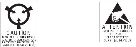
Electrostatic discharge (ESD)
Electrostatic discharge is a sudden current flowing from a charged object to another object or to ground. Electrostatic charges can accomulate on common items such as foam drinking cups, cellophane tape, synthetic clothing, untreated foam packaging material, and untreated plastic bags and work folders, to name only a few.
Electronic components and assemblies, if not properly protected against ESD, can be permanently damaged or destroyed when near or in contact with electrostatically charged objects. When you handle components or assemblies that are not in protective bags and you are not sure whether they are static-sensitive, assume that they are static-sensitive and handle them accordingly.
•Perform all service procedures in a static-protected environment. Always use techniques and equipment designed to protect personnel and equipment from electrostatic discharge.
•Remove static-sensitive components and assemblies from their static-shielding bags only at static-safe workstations - a properly grounded table and grounded floor mat - and only when you are wearing a grounded wrist strap (with a resistor of at least 1 megohm in series) or other grounding device.
•Use only grounded tools when inserting, adjusting, or removing static-sensitive components and assemblies.
•Remove or insert static-sensitive components and assemblies only with monitor power turned off.
•Insert and seal static-sensitive components and assemblies into their original staticshielding bags before removing them from static-protected areas.
Always test your ground strap, bench mat, conductive work surface, and ground cord before removing components and assemblies from their protective bags and before beginning any disassembly or assembly procedures.
8 |
Introduction |
Welch Allyn Spot Vital Signs |
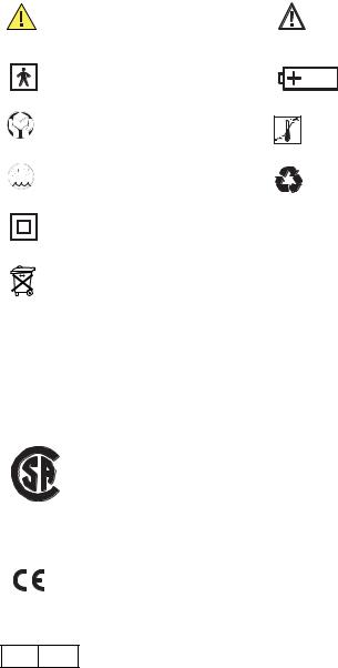
Symbols
The following symbols are associated with the Spot Vital Signs.
Safety symbols
Agency symbols
Identifies information within the manual to avoid injury or equipment failure.
Type BF Equipment
Handle with Care
Storage Humidity
Class II Equipment
Pb
IPXØ
Caution: consult accompanying documents
Internally Powered, Lead Acid
Battery
Transport Temperature
Recycle
Equipment is not protected against the ingress of liquid.
Do not dispose of this product as unsorted municipal waste. Prepare this product for reuse or separate collection as specified by Directive 2002/96/EC of the European Parliament and the Council of the European Union on Waste Electronic and Electrical Equipment (WEEE). If this product is contaminated, this directive does not apply.
For more specific disposal information, see www.welchallyn.com/weee, or contact Welch Allyn Customer Service at +44 207 365 6780.
Mode of Operation: Continuous
C |
US |
166292
CERTIFIED TO:
CAN/CSA STD C22.2 NO. 601.1
CONFORMS TO:
UL STD 60601-1
IEC 60601-1
0297
EC REP
The CE mark on this product indicates that it has been tested to and conforms with the provisions noted within the 93/42/EEC Medical Device Directive.
European Regulatory Manager Welch Allyn Ltd.
Navan Business Park • Dublin Road • Navan, County Meath, Republic of Ireland Tel.: +353 46 90 67700 • Fax: +353 46 90 67756

9
2 Overview
Purpose and scope
The Spot Vital Signs Service Manual is intended as a reference for maintenance and repair to the field replaceable unit (FRU) level and are listed on page 55. This manual provides the technical qualified service person with troubleshooting information, repair procedures, and calibration and performance verification instructions. A technical overview of the Spot subsystems is provided as an introduction to the device’s circuitry and pneumatics.
This manual is intended for the technical qualified service person. Service training classes on Welch Allyn’s products are available. Contact Welch Allyn Technical Service for information.
Other applicable documents
The Spot Vital Signs Directions for Use manual is also available. Refer to this document for information other than maintenance and repair.
Welch Allyn 9600 Plus Calibration Tester Directions for Use - for all models.
Masimo Directions for Use - for models 42M0B and 42MTB
Nellcor Directions for Use - for models 42N0B and 42NTB
10 |
Overview |
Welch Allyn Spot Vital Signs |
Contents checklist
Unpack the Welch Allyn Spot Vital Signs and applicable accessories, identify each item with the following checklist and inspect for missing items. Retain the shipping materials in the event of shipping damage or for return, if necessary, to Welch Allyn for repair or warranty service. All Spot Vital Signs include the following components:
Spot Vital Signs Device. This device automatically measures and displays blood pressure and pulse rate. Options include thermometry and pulse oximetry.
Directions for Use Manual. Read this manual thoroughly before using Spot Vital Signs. Save this manual for reference.
Warranty Card. This card validates the Spot Vital Signs warranty. Fill out the warranty card and mail it today.
Blood Pressure Cuff. Latex free blood pressure cuff with connectors. Other size cuffs are available separately.
Blood Pressure Hose. Latex-free pressure hose with connectors to attach various sizes of blood pressure cuffs to the Spot Vital Signs.
AC Power Transformer and Cord Assembly. Provides power to the Spot Vital Signs and charges the internal battery.
Quick Reference/Error Code Card. Attach this quick operating and error code guide to the device handle, mobile stand, or wall mount.
Possible attachments
Spot Vital Signs may include the following items based on the model and accessories purchased:
SureTemp Temperature Probe and Covers. One oral temperature probe (blue cap) and one box of 25 single-use, disposable probe covers.
Pulse Oximetry (SpO2). The finger clip SpO2 sensor and extension cable are for use with adult and pediatric patients. Other sensors are available separately.

Service Manual |
Overview |
11 |
Service
Caution Unauthorized repairs will void the warranty.
A Welch Allyn Service Center must perform all repairs on products under warranty.
Unauthorized repairs will void the warranty. Qualified electronics personnel or a Welch Allyn Service Center should repair products out of warranty.
Technical assistance
If you have an equipment problem that you cannot resolve, call the Welch Allyn Service Center nearest you for assistance. Technical service telephone support is available on normal business days.
If you are advised to return a product to Welch Allyn for repair or routine maintenance, schedule the repair with the service center nearest you.
Before returning a product for repair, you must obtain authorization from Welch Allyn. Service personnel will give you a Service Notification number. Returns without a Service Notification number will not be accepted for delivery.
If you need to return the Spot Vital Signs for service:
•Remove all hoses, cables, sensors, power cords, and any ancillary products not associated with the problem.
•Whenever possible, use the original shipping carton and packing materials.
•Include a packing list and the Welch Allyn Service Notification number.
•Note the Service Notification number on the outside of your shipping container.
It is recommended to insure all returned goods. The sender may initiate any claims for loss or damage to the product.
Field replacement units
Included with the Service Manual is a complete list of field replacement units. Order spare parts from your local Welch Allyn Service Center.
Service loaners
Service loaners are provided, on request, if a Welch Allyn Service Center provides repair service. Loaners for products repaired while under the original warranty, or while under service contract, are provided free of charge and are shipped within 48 hours of notification of need.
For service repairs outside of warranty or contract, loaners are available for a nominal charge and shipment is subject to availability. Loaners are shipped pre-paid; however, this charge is added to the service charges.

12 |
Overview |
Welch Allyn Spot Vital Signs |
Service intervals
Verify Spot Vital Signs annually for blood pressure calibration, temperature, and SpO2 accuracy.
Spot Vital Signs configurations
Table 2. Available Versions of Spot Vital Signs
REF |
Description |
|
|
4200B |
Spot Vital Signs with blood pressure only |
|
|
420TB |
Spot Vital Signs with blood pressure and SureTemp thermometer |
|
|
42MOB |
Spot Vital Signs with blood pressure and Masimo SpO2* |
42NOB |
Spot Vital Signs with blood pressure and Nellcor SpO2 |
42MTB |
Spot Vital Signs with blood pressure, SureTemp thermometer, and Masimo SpO2 * |
42NTB |
Spot Vital Signs with blood pressure, SureTemp thermometer, and Nellcor SpO2 |
* Version 2 configurations only.
Service Manual |
Overview |
13 |
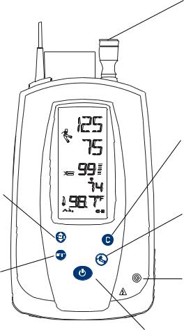
Controls
Figure 1. Spot Vital Signs with SureTemp Plus Thermometer (Version 1)
Thermometer Eject Button: push to remove used temperature probe cover.
Printer: press to print the measurements (Version 1 only).
Mode Button:
•holding for 2 seconds while the display is active turns off/on the backlight.
•in Standby Mode, recalls the last patient information.
•with the temperature probe removed from the probe holder, switches the temperature from Oral to Axillary Mode.
S S a mm g
DIA a mm g
SpO2
min
M


 P
P 
C
MODE
Next Patient/Clear/Cancel Button:
•active display: clears the display.
•in Standby Mode: recalls the last patient information. Pressing a second time clears the screen.
•cancels an active blood pressure measurement and deflates the cuff.
Blood Pressure Start/Stop Button: initiates a new blood pressure cycle. Pressing again cancels an active blood pressure measurement and deflates the cuff.
Pressure Hose Connector: port for blood pressure hose.
Power Button: controls power to the device.
14 |
Overview |
Welch Allyn Spot Vital Signs |
Figure 2. Spot Vital Signs with SureTemp Plus Thermometer (Version 2)
Thermometer Eject Button: push to remove used temperature probe cover.
Pressure Preset Button: press to change the factory inflation default for one reading (Version 2 only).
Mode Button:
•holding for 2 seconds while the display is active turns off/on the backlight.
•in Standby Mode, recalls the last patient information.
•with the temperature probe removed from the probe holder, switches the temperature from Oral to Axillary Mode.
S S a mm g
DIA a mm g
SpO2
min
Spot Vital Signs
Next Patient/Clear/Cancel Button:
•active display: clears the display.
•in Standby Mode: recalls the last patient information. Pressing a second time clears the screen.
•cancels an active blood pressure measurement and deflates the cuff.
Blood Pressure Start/Stop Button: initiates a new blood pressure cycle. Pressing again cancels an active blood pressure measurement and deflates the cuff.
Pressure Hose Connector: port for blood pressure hose.
Power Button: controls power to the device.
Service Manual |
Overview |
15 |
LCD (liquid crystal display)
The LCD may indicate any of the following: systolic blood pressure (mmHg or kPa), diastolic blood pressure (mmHg or kPa), temperature ( F or C), thermometer mode, pulse rate, pulse signal level, SpO2, MAP (mmHg or kPa), and battery charge level.
.
Option no longer available.
Date/Time: indicates that the user must set/re-set the current date and time.
Measurement Indicator:  displays the blood
pressure, SpO2, or temperature icon as Spot Vital Signs is taking the respective measurement.
Thermometer Mode icon: shows temperature mode (for devices with SureTemp only).
Temperature Probe Problem: indicates a temperature probe problem (for devices with SureTemp only).
S S |
mm g |
Systolic and Diastolic display: |
|
||
|
|
if MAP is turned on, the screen |
|
|
toggles between the systolic and |
|
|
diastolic values, and the word |
DIA mm g |
“MAP” and the MAP value. |
|
|
|
SpO2 Display: shows the percent saturation of arterial |
|
SpO2 |
hemoglobin (for devices with SpO2 only). |
Pulse Display: shows the pulse rate.
min |
Temperature Display and Indicator: shows the |
|
|
|
temperature in Fahrenheit or Celsius (for devices with |
|
SureTemp only). |
|
Monitor Mode Temperature: indicates the thermometer is |
M |
in Monitor Mode (for devices with SureTemp only). |
P |
Out-of-range indicator: shows the patient’s temperature |
|
|
|
reading above or below the measurement range limits (for |
|
devices with SureTemp only). |
|
Icon not used. |
Battery Level indicator: displays the battery charge level.
Battery Charging: indicates the device is powered through the AC power transformer.

16 |
Overview |
Welch Allyn Spot Vital Signs |
Connections
Use the following instructions to connect the blood pressure hose, thermometer probe, and optional attachments to the Spot Vital Signs.
Figure 3. Spot Side and Rear Panel Connections
Probe Cover Storage Compartment: storage space for one box of probe covers.
SpO2 Cable Connection Port
(for units with SpO2 only)
Temperature Probe Holder: 


 storage space for the

 temperature probe when not in


 use (for devices with SureTemp
 only).


Suretemp Thermometer  Connection Port (for

 devices with SureTemp only).
IR Data Interface: Port for communicating with an external device.
Battery Door
DC Power
Connection Port
Threaded Insert: to mount the
Spot Vital Signs to a mobile stand.
Service Manual |
Overview |
17 |
Blood pressure hose and cuff connections
Have available the Spot Vital Signs, blood pressure cuff, and blood pressure hose.
1.Inspect the pressure hose; note that one end has a connector fitting and the other end does not. Attach the end without the connector fitting to the pressure hose connector (see page 14). Verify that the pressure hose is completely inserted over the connector and that the fit is snug.
2.Join the other end of the pressure hose to the blood pressure cuff pneumatic tubing. Twist the connectors together until finger-tight. DO NOT OVERTIGHTEN.
Temperature probe connection
The Welch Allyn Spot Vital Signs is available with two probes — one for oral/axillary temperatures (blue cap), and one for rectal temperatures (red cap). The rectal probe is an accessory item that is ordered separately.
Press down on the tab on top of the connector and insert the connector into the temperature probe connector port on the back of the Spot Vital Signs. The probe connector only fits into Spot Vital Signs one way. Verify the connector clicks into place. Insert the temperature probe into the probe holder on the top of the Spot Vital Signs.
To remove the temperature probe, press down on the connector tab and lift out.
SpO2 sensor
Spot Vital Signs is available with a wide variety of SpO2 sensors and ships with a reusable finger sensor and extension cable. All other sensors are accessory items that are sold separately.
1.Align the shape and pin configuration of the extension cable connector to the SpO2 cable connection port on the top side of the Spot Vital Signs device.
2.Push the connector firmly into the SpO2 cable connection port.
3.Align the opposite end of the extension cable to the sensor cable connector and firmly push them together.
Note Use only Masimo or Nellcor SpO2 sensors and accessories with the Spot Vital Signs with Masimo or Nellcor configurations, respectively.
Quick reference card
Attach the Quick Reference Card to the Spot handle, mobile stand, or wall mount using the supplied plastic cable tie.
18 |
Overview |
Welch Allyn Spot Vital Signs |
DCpower connection
Note To assure proper electrical isolation, replace the AC power transformer/charger using only the Welch Allyn specified part (REF 5200-101A, 5200-103A, 5200103Z).
Use the Spot Vital Signs with battery power (after charging the battery) or battery and DC power supply.
1.Insert the round transformer connector into the DC power connection port on the left of the Spot Vital Signs (see page 16).
2.Insert the line cord into the line connector on the transformer then plug the power cord on the transformer into the AC main power source to charge the battery.
Charging the battery
CHARGE THE BATTERY FOR SIXTEEN (16) HOURS PRIOR TO INITIAL USE.
Attach the DC power transformer to the Spot Vital Signs then plug the transformer into the AC main power source.
While charging, the charger icon remains on and the battery icon segments continuously sequence. When the battery is fully charged, all battery icon segments display.
As the battery voltage level drops the segments turn off from left to right. If the Spot Vital Signs is not plugged in to charge when the second last segment is turned off the Spot Vital Signs issues a warning beep. As the voltage level drops to compromise measurements an error beep is heard and all other display fields turn off. Spot Vital Signs beeps at increasingly frequent intervals until it finally powers itself off.
If not used for extended periods of time then recharge the battery.
Standby mode
Standby Mode conserves battery power. When the device is powered up, but has not been used for 2 minutes, it goes into Standby Mode. “Z Z Z” shows across the top of the display with no backlight.
To bring the Spot Vital Signs out of Standby Mode, press the Mode or Pressure Preset button or begin a patient measurement.

19
3 Functional overview
This functional verification procedure helps to confirm the proper operation of the Spot Vital Signs and options. This procedure supports the requirements of routine preventative maintenance. It is not necessary to disassemble the Spot Vital Signs to perform this procedure.
For the calibration procedures, see “Calibration” on page 25. If the Spot Vital Signs fails certain functional tests or a circuit board is replaced, the device may require calibration. It is necessary to disassemble the Spot Vital Signs for calibration.
Always perform this functional verification procedure after performing any calibration. This procedure contains additional tests that are not included in calibration procedures.
Power on/off and system check procedure
Press the Power button to turn the device on or off. Upon each power up, all the LCD segments in each display turn on briefly and two beeps sound. If the internal self-check is successful, the display shows its normal functions (see page 15) and the device is ready for operation. If the self-check fails, an error code is shown in the on the display.
To turn the unit off, press the Power button.
Note Turning the unit off erases measurement data.

20 |
Functional overview |
Welch Allyn Spot Vital Signs |
Internal configuration mode
You can change several device operating parameters in the Internal Configuration Mode. When changed, these settings become the default power-up settings. You will also see non-changeable device configurations for technical service purposes.
To enter the Configuration Mode:
1.Turn the Spot Vital Signs off.
2.Press and hold the Power - Blood Pressure Start/Stop buttons. The device enters the Internal Configuration Mode and displays the software version.
3.Press the Mode button to cycle through the Internal Configuration menu until you see the menu option displayed on the screen.
4.Use the Next Patient/Clear/Cancel or Blood Pressure Start/Stop button to change the default setting.
5.Press the Mode button once to save the change and press the Power button to exit the Internal Configuration Mode.
Table 3. Configuration Menu Options
Setting |
Description |
|
|
Blood Pressure Calibration |
Prepares the Spot Vital Signs for calibration. Only qualified personnel should verify the |
Displays “Cal” |
Spot Vital Signs blood pressure calibration. For more details, see “Blood pressure |
|
calibration” on page 27. |
Inflation Pressure Preset Level |
120, 140, 160, 180, 200, 240, 280 mmHg. Factory default is 160 mmHg. |
Displays “PrP” |
|
Pressure Preset Level |
On or off. Disables or enables the front panel Pressure Preset button. |
Displays “PrP“ |
|
Backlight |
On or off. |
Displays “BLT” |
|
Mean Arterial Pressure |
On or off. |
Displays “MAP” |
|
Date/Time |
Changes or updates the actual date and time. |
Temperature Scale |
Fahrenheit (°F) or Celsius (°C) Normal Mode / Fahrenheit (°F) or Celsius (°C) Monitor |
Displays “TMP MOD” |
Mode |
Blood Pressure Units |
mmHg or kPa. |
Displays “BP” |
|
Battery Readings |
Displays the total battery voltage. |
Displays “BAT” |
|
Battery Life |
Total number unit measurements. Displayed information only; operator cannot change. |
Displays “LFE” |
|
|
|
Service Manual |
Functional overview |
21 |
Functional verification
Complete all steps in this section before returning a Spot Vital Signs for service.
Verify that the pressure meter used (if not specified by this service manual) is calibrated and the calibration certificate of the meter is traceable to NIST. The pressure meter testing the Spot Vital Signs must have an accuracy of better than "3 mmHg.
Subtract the rated accuracy of the pressure measurement standard from the "3 mmHg rated accuracy of Spot Vital Signs. This is the pass/fail criteria to determine if the device is within calibration. If the differences between Spot Vital Signs and the pressure measurement standard are within the pass/fail criteria at all specified pressures, then the device is within calibration.
All test specifications are found in Appendix A.
1.Use the pneumatic tubing to connect the Spot Vital Signs to the test station (page 26). Disconnect the battery and connect the power supply. Verify the IR Data Interface is free from obstacles.
2.Open the Spot Vital Signs repair software and verify the computer is communicating with the Spot Vital Signs.
3.Hold down the Blood Pressure Start/Stop button while powering on the Spot Vital Signs. The Spot Vital Signs enters the configuration test mode. After the LCD displays the software versions press the Mode button to display CAL. Spot Vital Signs automatically performs an auto zero.
4.Attach a pneumatic clamp to the 100 cc and the 250 cc cylinder and then remove the clamp from the 500 cc cylinder.
5.Select Test/Calibration on the computer screen. The dialog box displays the Spot Vital Signs manometer and battery readings and the valve and pump status.
To verify the blood pressure calibration:
1.Push the Spot Vital Signs Blood Pressure Start/Stop button to close the valve.
2.Pump the hand bulb to the set the pressures: 0 mmHg, 50 "5 mmHg, 150 "5 mmHg, 250 "5 mmHg. Verify each pressure is within "3 mmHg of the target pressure (except for 0 mmHg which should be within "1.0 mmHg).
3.Press the Mode button until the LCD window reads “bat.”
To verify the voltage reading:
1.Set the power supply to 5.6 (+0.3 / -0.0 Vdc).
2.Verify that the voltage reading meets the test specification.
3.Return the power supply to 6.5 Vdc (+0/- 0.25 Vdc) upon completion of this test.
4.Select OK to exit the Test Calibration dialog box.
22 |
Functional overview |
Welch Allyn Spot Vital Signs |
NOTE: The pass/fail criteria for the blood pressure calibration check depends upon the accuracy of the pressure measurement standard used.
•If the pressure measurement standard used is rated with an accuracy of ±0.1 mmHg, the pass/fail criteria is ±2.9 mmHg in order to guarantee that the instrument under test is within ±3 mmHg of NIST.
•If the pressure measurement standard used is rated with an accuracy of ±1.0 mmHg, the pass/fail criteria is ±2.0 mmHg in order to guarantee that the instrument under test is within ±3 mmHg of NIST
Temperature functional check
The 9600 Plus Calibration Tester takes approximately 20 minutes to heat to the lowest setting. When testing several thermometers at all three temperatures, it is recommended to test all probes at one Calibration Set Point Temperature before proceeding to the next Calibration Set Point Temperature.
To further expedite testing start at the lowest Calibration Set Point Temperature. The 9600 Plus Calibration Tester does not have an internal fan, this causes a longer cool down time than warm up time.
Refer to the 9600 Plus Calibration Tester Directions for Use manual for specific information regarding the LCD window or the control buttons.
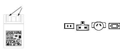
1.Choose the proper mains plug insert and slide it over the two prongs in the power converter.
Figure 4. Power Adapter and Mains Plug Inserts
Two prongs in the power adapter
11.8593./US |
|
11.8593./AUS |
11.8593./EU |
|
|
||
|
11.8593./UK |
|
|
(US) |
(UK) |
(AUS) |
(EU) |
US |
UK |
AUS |
EU |
2.Plug the power adapter into the 9600 Plus Calibration Tester (Figure 4) and the opposite end into a wall outlet.
3.Place the 9600 Plus Calibration Tester on a level surface away from sunlight, drafts, and other sources of heat or cold.
4.Observe the Set Point Mode in the upper left hand corner of the LCD display. If the unit displays a "D", it is in Default Mode and will heat to the lowest Set Point Temperature. If you do not want to conduct testing at this Set Point Temperature, press and hold the Temperature Selection button to select the desired setting. The temperature display will flash before staying on continuously to indicate the 9600 Plus Calibration Tester has stabilized and is ready for use.
Loading...