


Connex Integrated Wall System
Table of contents
 Loading...
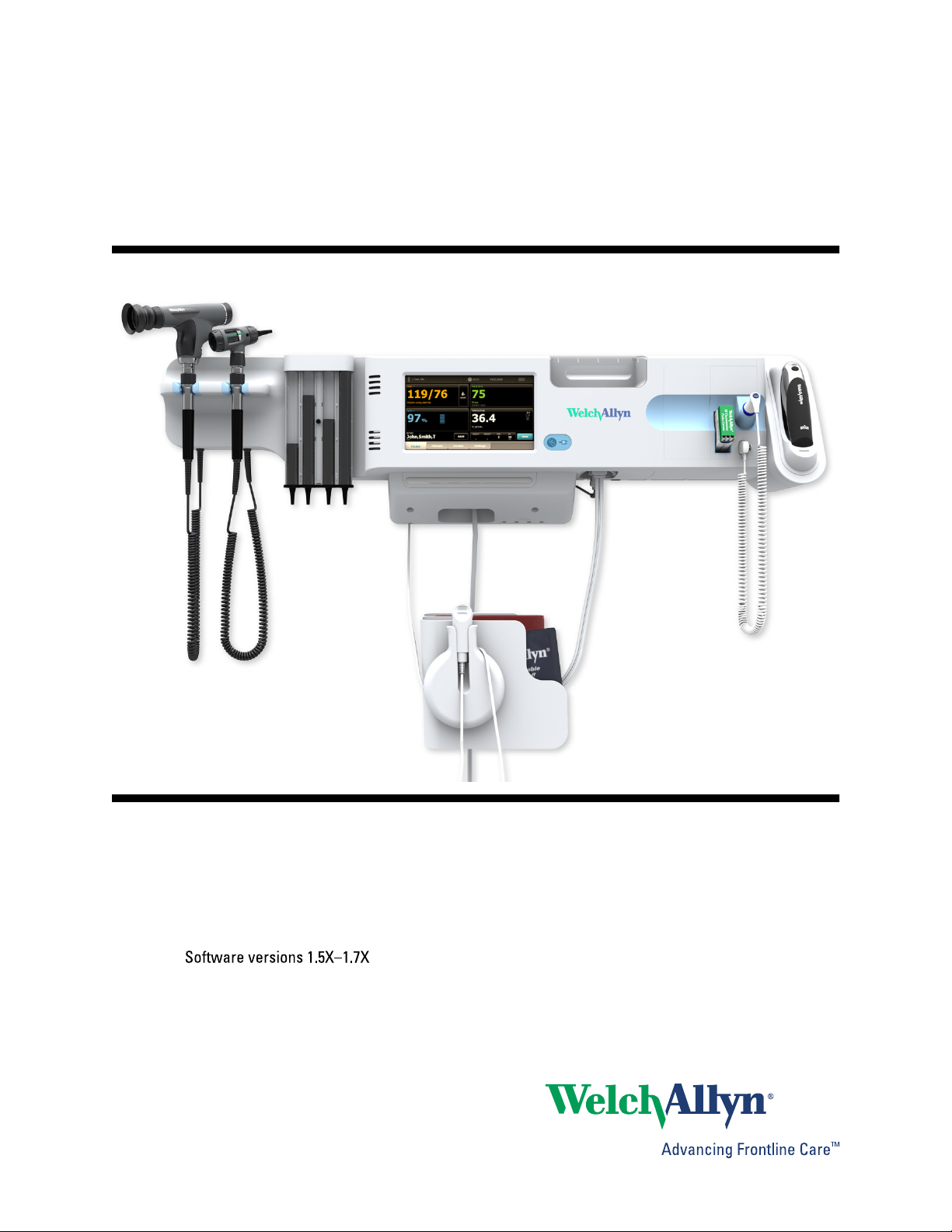
Welch Allyn Connex
®
Integrated
Wall System
Directions for use

© 2012 Welch Allyn. All rights are reserved. To support the intended use of the product described in this publication, the
purchaser of the product is permitted to copy this publication, for internal distribution only, from the media provided by Welch
Allyn. No other use, reproduction, or distribution of this publication, or any part of it, is permitted without written permission from
Welch Allyn. Welch Allyn assumes no responsibility for any injury to anyone, or for any illegal or improper use of the product, that
may result from failure to use this product in accordance with the instructions, cautions, warnings, or statement of intended use
published in this manual.
Welch Allyn, Connex, SureTemp, FlexiPort, and SureBP are registered trademarks of Welch Allyn.
Vital Signs Monitor 6000 Series is a trademark of Welch Allyn.
LNCS, SpHb, ReSposable , and Rainbow are trademarks of, and SET, LNOP, and Masimo are registered trademarks of, Masimo
Corporation. Possession or purchase of a Masimo SpO2- or MasimoSpHb-equipped device does not convey any express or
implied license to use the device with unauthorized sensors or cables which would, alone or in combination with this device, fall
within the scope of one or more of the patents relating to this device.
Nellcor and OxiMax are registered trademarks of Nellcor Puritan Bennett Inc.
Braun and ThermoScan are registered trademarks of Braun GmbH.
Health o meter is a registered trademark of Sunbeam Products, Inc., used under license.
Software in this product is Copyright 2012 Welch Allyn or its vendors. All rights are reserved. The software is protected by United
States of America copyright laws and international treaty provisions applicable worldwide. Under such laws, the licensee is
entitled to use the copy of the software incorporated with this instrument as intended in the operation of the product in which it is
embedded. The software may not be copied, decompiled, reverse-engineered, disassembled, or otherwise reduced to human-
perceivable form. This is not a sale of the software or any copy of the software; all right, title, and ownership of the software
remain with Welch Allyn or its vendors.
For information about any Welch Allyn product, call Welch Allyn Technical Support:
USA
Canada
European Call Center
Germany
Japan
Malaysia
Singapore
Spain
United Kingdom
+1 800 535 6663
+1 315 685 4560
+1 800 561 8797
+353 46 90 67790
+49 695 098 5132
+81 42 703 6084
+603 7884 3329
+65 6419 8100
+34 917 499 357
+44 207 365 6780
Australia
China
France
Italy
Latin America
Netherlands
South Africa
Sweden
+61 2 9638 3000
+86 21 6327 9631
+33 155 69 58 49
+39 026 968 2425
+1 305 669 9003
+31 202 061 360
+27 11 777 7555
+46 85 853 6551
Software version 1.5X–1.7X
104066 (CD)
80016142 Ver. H
104069 (printed copy)
Material Number 718745, 80016142 Ver. H
Welch Allyn, Inc.
4341 State Street Road
Skaneateles Falls, NY 13153-0220 USA
www.welchallyn.com
Regulatory Affairs Representative
Welch Allyn Limited
Navan Business Park
Dublin Road
Navan, County Meath
Republic of Ireland

Contents
Introduction ............................................................................................. 1
Intended use ...................................................................................................................................... 1
Contraindications .............................................................................................................................. 2
Symbols ................................................................................................... 3
Screen elements ...................................................................................... 5
About warnings and cautions ................................................................ 9
General warnings and cautions ..................................................................................................... 9
Controls, indicators, and connectors ................................................... 13
Setup ...................................................................................................... 17
Supplies and accessories ............................................................................................................. 17
Unpack the wall system ................................................................................................................. 17
Insert the battery ............................................................................................................................. 18
Prepare for mounting ..................................................................................................................... 19
Mounting location ........................................................................................................................... 20
Mount the wall system ................................................................................................................... 21
Mount the accessory bin ............................................................................................................... 25
Connect the blood pressure (NIBP) hose ................................................................................... 26
Set up the physical assessment instrument handles and specula dispenser ..................... 27
Set up the SureTemp® Plus thermometer ................................................................................. 27
Set up the Braun ThermoScan® PRO 4000 thermometer ........................................................ 28
Connect AC power .......................................................................................................................... 29
Attach an accessory ...................................................................................................................... 30
Startup .................................................................................................... 33
Power ................................................................................................................................................ 33
Power up the monitor ..................................................................................................................... 34
Power down the monitor ............................................................................................................... 35
Reset the wall system .................................................................................................................... 35
Select a language ........................................................................................................................... 36
Set the date and time ..................................................................................................................... 36
Enter clinician information ............................................................................................................ 36
Set the default configuration ........................................................................................................ 37
Navigation .............................................................................................. 39
Home tab .......................................................................................................................................... 39
Device Status area ......................................................................................................................... 39
iii

Content area .................................................................................................................................... 41
Navigation area ............................................................................................................................... 42
Profiles ................................................................................................... 45
Select a profile ................................................................................................................................ 48
Using the keypad, keyboard, and barcode scanner ........................... 49
Open the numeric keypad .............................................................................................................. 49
Numeric keypad .............................................................................................................................. 49
Enter a number ................................................................................................................................ 50
Close the numeric keypad ............................................................................................................. 50
Open the keyboard .......................................................................................................................... 50
Keyboard .......................................................................................................................................... 50
Enter a letter or number ................................................................................................................. 52
Enter a symbol or special character ............................................................................................ 52
Enter a diacritical mark .................................................................................................................. 52
Close the keyboard ......................................................................................................................... 53
Use a barcode scanner .................................................................................................................. 53
Patient data management .................................................................... 55
Add a patient to the patient list ..................................................................................................... 55
Load patient data with the barcode scanner ............................................................................. 55
Select a patient ............................................................................................................................... 56
Manage patient records ................................................................................................................ 56
Delete a patient from the list ......................................................................................................... 57
Modifiers .......................................................................................................................................... 57
Set modifiers .................................................................................................................................... 58
Alarms .................................................................................................... 59
Reset (pause or turn off) audio alarms ........................................................................................ 62
Adjust vital sign alarm limits ......................................................................................................... 63
Modify audio alarm notification .................................................................................................... 63
Alarm messages and priorities ..................................................................................................... 64
Nurse call ......................................................................................................................................... 67
Patient monitoring ................................................................................ 69
NIBP .................................................................................................................................................. 69
Temperature .................................................................................................................................... 77
SpO2 .................................................................................................................................................. 87
SpHb .................................................................................................................................................. 92
Pulse rate frame .............................................................................................................................. 95
Manual parameters frame ............................................................................................................. 96
Physical assessment instrument handles ........................................... 99
Use the physical assessment instrument handles .................................................................... 99
Maintenance and service .................................................................... 101
Perform periodic checks ............................................................................................................. 101
Remove the wall system from the wall ...................................................................................... 101
Change the battery ....................................................................................................................... 103
Clean the wall system (excluding handle cradles and accessories) .................................. 104
Clean the handle cradles ............................................................................................................. 105
iv Contents Welch Allyn Connex
®
Integrated Wall System

Clean the wall system accessories ........................................................................................... 105
Specifications ...................................................................................... 107
Physical specifications ................................................................................................................ 107
Environmental specifications ...................................................................................................... 111
Monitor radio ................................................................................................................................. 112
Configuration options ................................................................................................................... 113
Patents ............................................................................................................................................ 113
Standards and compliance ................................................................. 115
General compliance and standards ........................................................................................... 115
General radio compliance ........................................................................................................... 116
Guidance and manufacturer's declaration ........................................ 119
EMC compliance ........................................................................................................................... 119
Emissions and immunity information ......................................................................................... 119
Advanced settings ............................................................................... 123
General ........................................................................................................................................... 123
Parameters ..................................................................................................................................... 127
Data management ......................................................................................................................... 131
Network .......................................................................................................................................... 134
Service ............................................................................................................................................ 136
Troubleshooting .................................................................................. 137
NIBP messages ............................................................................................................................. 137
SpO2 and SpHb messages .......................................................................................................... 138
Temperature messages ............................................................................................................... 139
Weight scale messages ............................................................................................................... 140
Physical assessment instrument handles ................................................................................ 140
Patient data management messages ........................................................................................ 141
Radio messages ............................................................................................................................ 141
Ethernet messages ....................................................................................................................... 142
USB messages .............................................................................................................................. 142
System messages ......................................................................................................................... 142
Battery power manager messages ............................................................................................ 143
Configuration Manager messages ............................................................................................. 143
Problems and solutions ................................................................................................................ 144
Appendix .............................................................................................. 145
Approved accessories ................................................................................................................ 145
Warranty ......................................................................................................................................... 154
Directions for use Contents v

vi Contents Welch Allyn Connex
®
Integrated Wall System

Introduction
The Welch Allyn Connex® Integrated Wall System combines the advanced, easy-to-use monitor
capabilities of the Welch Allyn Connex® Vital Signs Monitor 6000 Series with the Welch Allyn 767
Power Handles. This manual (directions for use) is designed to help you understand the
capabilities and operation of the wall system. The information in this manual, including the
illustrations, is based on a wall system configured with non-invasive blood pressure (NIBP), body
temperature, pulse oximetry (SpO2), total hemoglobin concentration (SpHb), pulse rate, weight
scale, and two power handles. If your wall system configuration lacks any of these options, some
information in this manual may not apply.
Before using the wall system, read the sections of the manual that pertain to your use of the
system.
Note Throughout this directions for use, the Integrated Wall System may be referred to
as a wall system or monitor.
Note Some product features described in this publication might not be available in your
country. For the latest information about products and features, please call Welch
Allyn Customer Care.
Intended use
Handle module assembly
Handles supply power to Welch Allyn 3.5V instruments.
Connex® Vital Signs Monitor patient monitor
The VSM 6000 Series of monitors is intended to be used by clinicians and medically qualified
personnel for monitoring of neonatal, pediatric, and adult patients for
•
noninvasive blood pressure,
• pulse rate,
• noninvasive functional oxygen saturation of arteriolar hemoglobin (SpO2), and
• body temperature in normal and axillary modes
The most likely locations for patients to be monitored are general medical and surgical floors,
general hospital, and alternate care environments.
The optional Masimo Rainbow SET® and accessories are indicated for the continuous noninvasive
monitoring of total hemoglobin concentration of adult, pediatric, and neonatal patients during both
1

motion and no motion conditions, and for patients who are well or poorly perfused in hospitals and
hospital-type facilities.
Optional compatible weight scales (e.g., Health o meter®) can be used for height, weight, and BMI
input.
This product is available for sale only upon the order of a physician or licensed health care
professional.
Contraindications
This system is not intended to be used:
•
on patients connected to heart/lung machines
• on patients being transported outside a healthcare facility
• near an MRI machine
• in a hyperbaric chamber
• near flammable anesthetics
• near electro-cauterization devices
For contraindications of SpO2 and SpHb sensors, consult the sensor manufacturer's directions for
use.
2
Introduction Welch Allyn Connex
®
Integrated Wall System
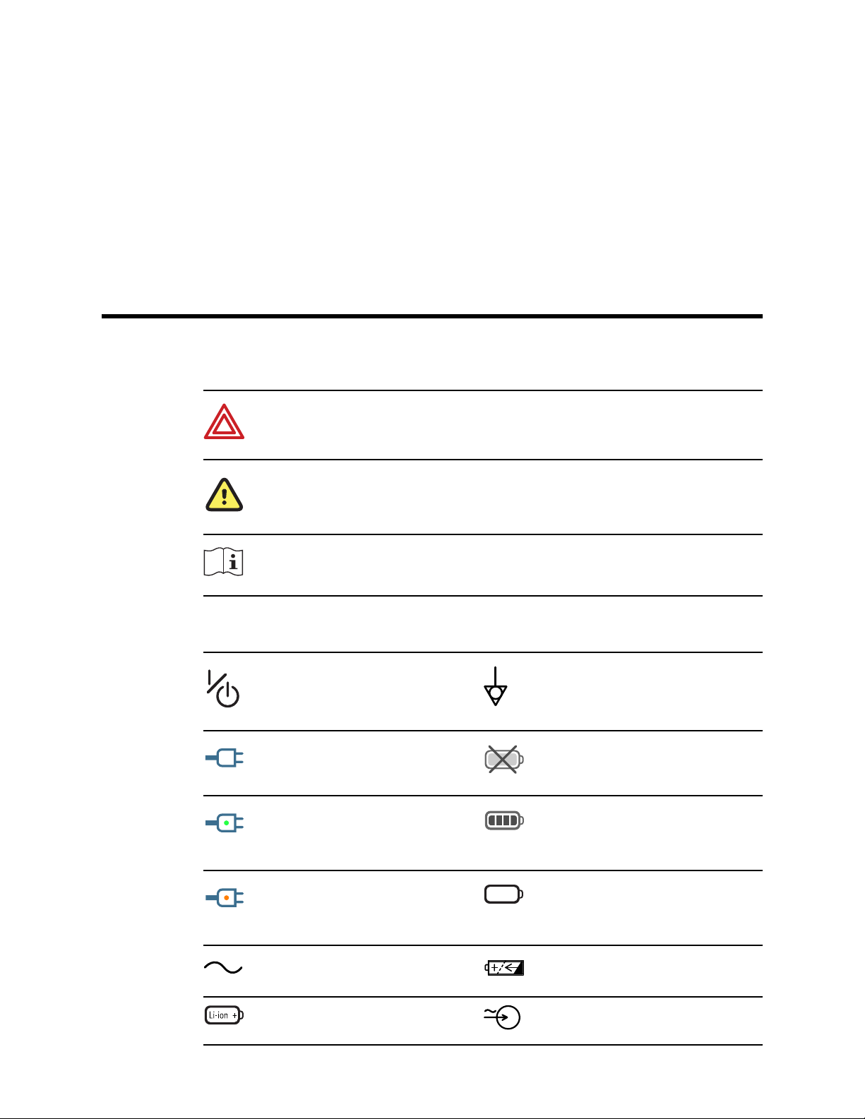
Symbols
Documentation symbols
WARNING The warning statements in this manual identify conditions or practices
that could lead to illness, injury, or death.
Caution The caution statements in this manual identify conditions or practices that
could result in damage to the equipment or other property, or loss of data. This
definition applies to both yellow and black and white symbols.
Consult operating instructions.
Power symbols
Power on/standby Equipotential terminal
(on the display) monitor is
plugged into Alternating
Current power
Battery absent or faulty
(on the monitor, green
indicator) Alternating Current
power present, battery fully
charged
Battery charge level
(on the monitor, amber
indicator) Alternating Current
power present, battery is
charging
Battery cover
Alternating Current (AC) Rechargeable battery
Li-ion battery AC input power
3
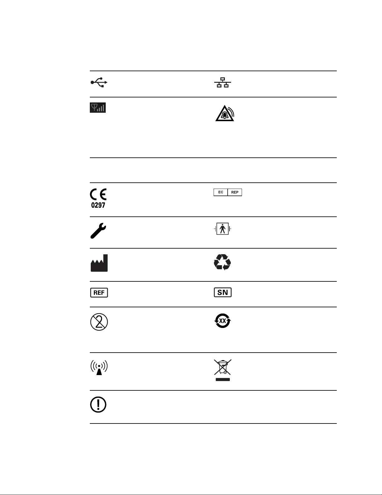
Connectivity symbols
USB Ethernet RJ-45
Wireless signal strength
• Best (4 bars)
• Good (3 bars)
• Fair (2 bars)
• Weak (1 bar)
• No signal (no bars)
• No connection (blank)
Nurse call
Miscellaneous symbols
Meets essential requirements
of European Medical Device
Directive 93/42/EEC
Authorized Representative in
the European Community
Call for maintenance Defibrillation-proof Type BF
applied parts
Manufacturer Recycle
Reorder number Serial number
Do not reuse China RoHS markings for
control of pollution caused by
electronic information
products. XX indicates
Environmentally Friendly Use
Period in years.
Nonionizing electromagnetic
radiation
Recycle the product separate
from other disposables
Restrictions for use of
wireless device in Europe.
European Community's Class
2 radio equipment.
4 Symbols Welch Allyn Connex
®
Integrated Wall System
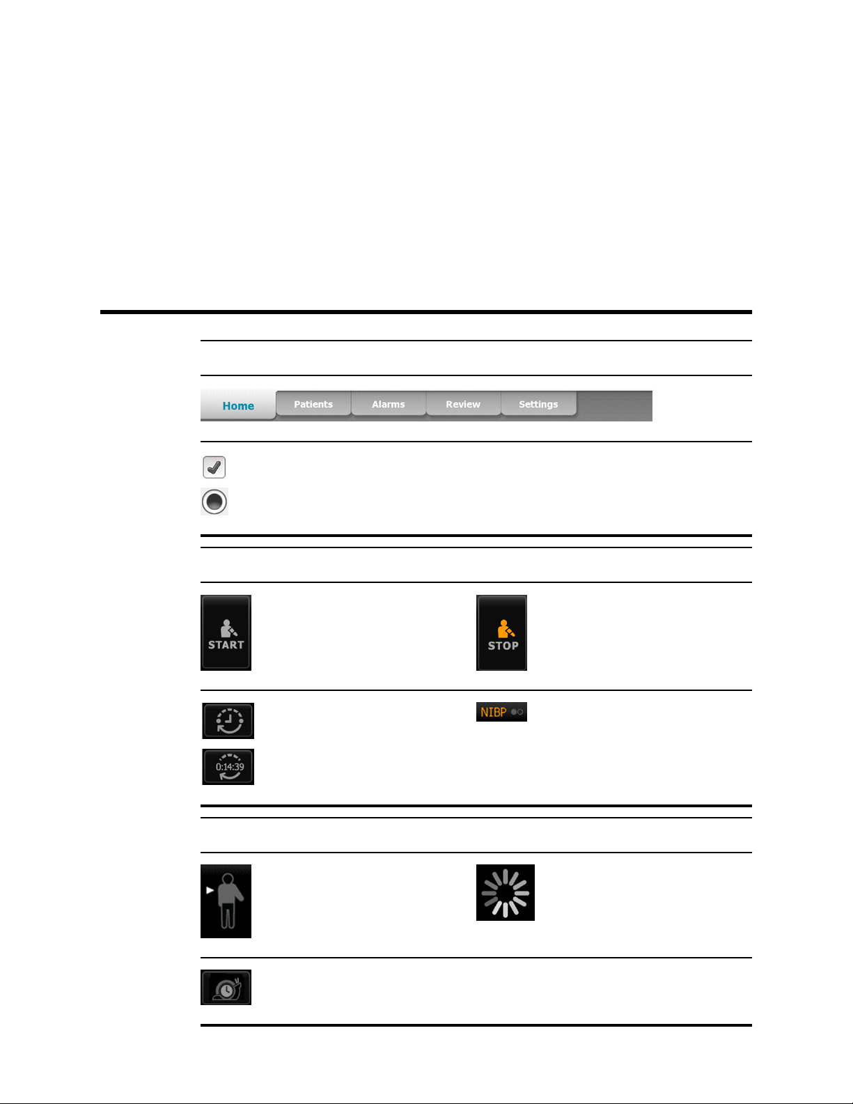
Screen elements
Global navigation
Select option
NIBP
NIBP start NIBP stop
Intervals status indicators NIBP view toggle
Temperature
Temperature site control Process indicator
Direct mode selector
5
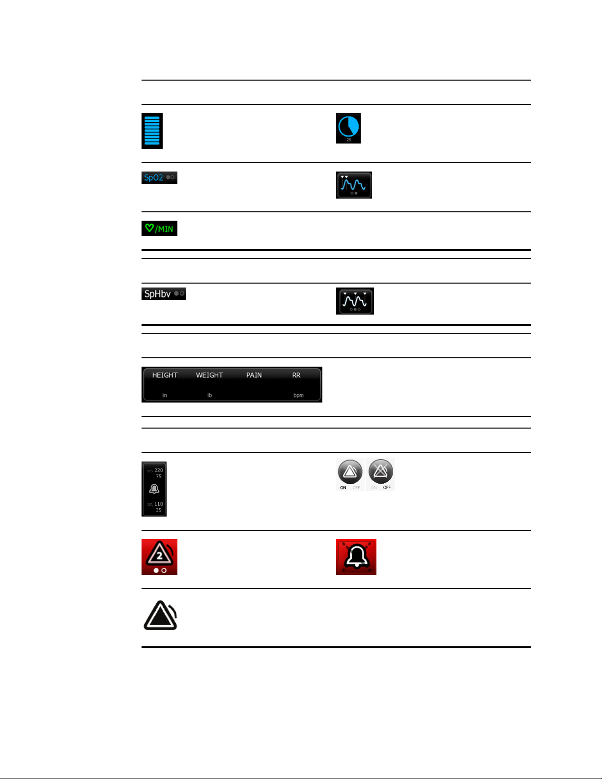
SpO2 and Pulse rate
Pulse amplitude bar SatSeconds timer (Nellcor
feature only)
SpO2 view toggle Response mode selector
(touch for Fast mode)
Heart rate (in beats per
minute)
Total hemoglobin (SpHb)
SpHb view toggle Averaging selector
Manual parameters
Manual parameter
selector
Alarm and information messages
Alarm limit button
Alarm On/Off toggle
Multiple alarms toggle Alarm audio paused
Alarm active
6 Screen elements Welch Allyn Connex
®
Integrated Wall System
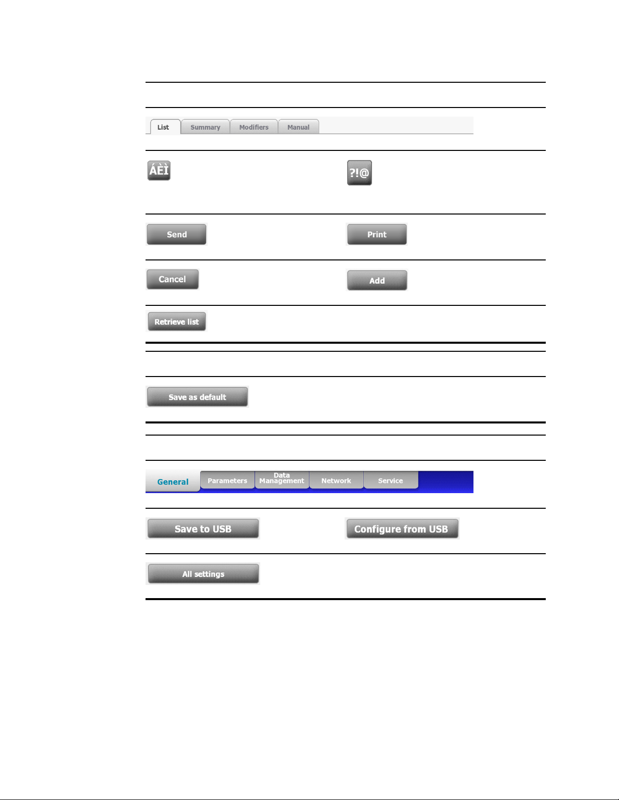
Patients list and review
Diacritical marks key
(available for languages
that use diacritical marks;
appearance differs based
on language)
Symbols key
Send patient test reports Print patient test reports
Cancel print request
(Not available)
Add patient identifiers
Retrieve the patient list
from the network
Settings
Save configuration
settings
Advanced settings
Save to USB flash
drive
Configure from USB
flash drive
Restore factory
default settings
Directions for use Screen elements 7

8 Screen elements Welch Allyn Connex
®
Integrated Wall System

About warnings and cautions
Warning and caution statements can appear on the monitor, on the packaging, on the shipping
container, or in this document.
The monitor is safe for patients and clinicians when used in accordance with the instructions and
the warning and caution statements presented in this manual.
Before using the monitor, familiarize yourself with the sections of this directions for use that
pertain to your use of the monitor.
•
Failure to understand and observe any warning statement in this manual could lead to patient
injury, illness, or death.
• Failure to understand and observe any caution statement in this manual could lead to damage
to the equipment or other property, or loss of patient data.
General warnings and cautions
WARNING Many environmental variables, including patient physiology and
clinical application, can affect the accuracy and performance of the monitor. The
clinician must verify all vital signs information before treating the patient. If there is
any question about the accuracy of a measurement, verify the measurement using
another clinically accepted method.
WARNING Alarm limits are patient- or facility-specific. The clinician must set or
verify alarm limits appropriate for each patient. Each time the monitor is powered
on, you must check that the alarm settings are appropriate for your patient before
you start monitoring.
WARNING Use only Welch Allyn approved accessories, and use them according
to the manufacturer’s directions for use. Using unapproved accessories with the
monitor can affect patient and operator safety and can compromise product
performance and accuracy.
WARNING Inaccurate measurement risk. Do not connect more than one patient
to a monitor.
WARNING Inaccurate measurement risk. Dust and particle ingress can affect the
accuracy of blood pressure measurements. Use the monitor in clean environments
to ensure measurement accuracy. If you notice dust or lint build-up on the monitor's
vent openings, have the monitor inspected and cleaned by a qualified service
technician.
9

WARNING Liquids can damage electronics inside the Connex IWS. Prevent
liquids from spilling on the wall system.
If liquids are spilled on the wall system:
1. Power down the wall system.
2. Disconnect the power plug.
3. Remove the wall system from the wall.
4. Remove battery pack from the wall system.
5. Dry off excess liquid from the wall system.
Note If liquids possibly entered the wall system, remove the wall system
from use until it has been properly dried, inspected, and tested by
qualified service personnel.
6. Reinstall battery pack.
7. Mount the wall system on the wall.
8. Power on the wall system and verify that it functions normally before using it.
WARNING Safety risk. Damaged cords, cables, and accessories can affect
patient and operator safety. Routinely inspect the AC power cord, blood pressure
cuff, SpO2 cable, and other accessories for strain relief wear, fraying, or other
damage. Replace as necessary.
WARNING Fire and explosion hazard. Do not operate the monitor in the presence
of a flammable anesthetic mixture with air, oxygen, or nitrous oxide; in oxygen-
enriched environments; or in any other potentially explosive environment.
WARNING Fire and shock hazard. Only connect LAN cables contained within the
perimeter of a single building. Conductive LAN cables spanning multiple buildings
may introduce fire or shock hazards unless they are fitted with fiber optic cables,
lightning arrestors, or other applicable safety features.
WARNING The monitor may not function properly if dropped or damaged. Protect
it from severe impact and shock. Do not use the monitor if you notice any signs of
damage. Qualified service personnel must check any monitor that is dropped or
damaged for proper operation before putting the monitor back into use.
WARNING Defective batteries can damage the monitor. If the battery shows any
signs of damage or cracking, it must be replaced immediately and only with a
battery approved by Welch Allyn.
WARNING Improper disposal of batteries may create an explosion or
contamination hazard. Never dispose of batteries in refuse containers. Always
recycle batteries according to local regulations.
WARNING Electric shock hazard. Do not open the monitor or attempt repairs. The
monitor has no user-serviceable internal parts. Only perform routine cleaning and
maintenance procedures specifically described in this manual. Inspection and
servicing of internal parts shall only be performed by qualified service personnel.
WARNING Inaccurate measurement risk. Do not expose to temperatures higher
than 122º F (50º C).
WARNING Inaccurate measurement risk. Do not use the monitor on patients who
are on heart-lung machines.
WARNING Use the monitor only as described in this directions for use. Do not
use the monitor on patients as described in the Contraindications.
10 About warnings and cautions Welch Allyn Connex
®
Integrated Wall System

WARNING Inaccurate measurement risk. Do not use the monitor on patients who
are experiencing convulsions or tremors.
WARNING Do not place the monitor in any position that might cause it to fall on
the patient.
WARNING Welch Allyn is not responsible for the integrity of a facility's power. If
the integrity of a facility's power or protective earth conductor is in doubt, always
operate the monitor on battery power alone when it is attached to a patient.
WARNING For operator and patient safety, peripheral equipment and
accessories that can come in direct patient contact must comply with all applicable
safety, EMC, and regulatory requirements.
WARNING All signal input and output (I/O) connectors are intended for
connection of only devices complying with IEC 60601-1, or other IEC standards (for
example, IEC 60950), as applicable to the monitor. Connecting additional devices to
the monitor may increase chassis or patient leakage currents. To maintain operator
and patient safety, consider the requirements of IEC 60601-1-1. Measure the
leakage currents to confirm that no electric shock hazard exists.
WARNING Equipment failure and patient harm risk. Do not cover the air intake
vents on the right or exhaust vents on the front of the Connex IWS. Covering these
vents could cause overheating or muffling of alarms.
WARNING This equipment is not suitable for use in the presence of electro-
surgery.
WARNING Cross-contamination or nosocomial infection risk. Clean and disinfect
the monitor on a routine basis according to your facility's protocols and standards
or local regulations. Thorough hand-washing before and after contact with patients
greatly reduces the risk of cross-contamination and nosocomial infection.
WARNING The physical assessment instruments (handles) are designed for
intermittent use. On-time should not exceed 2 minutes. Allow at least 10 minutes off-
time between patients.
CAUTION United States Federal law restricts this monitor to sale, distribution, or
use by or on the order of a physician or licensed healthcare professional.
CAUTION Welch Allyn is not responsible for the integrity of any wall mounting
interface. Welch Allyn recommends that you contact your Biomedical Engineering
Department or maintenance service to ensure professional installation, safety, and
reliability of any mounting accessory.
CAUTION Electromagnetic interference risk. The monitor complies with
applicable domestic and international standards for electromagnetic interference.
These standards are intended to minimize medical equipment electromagnetic
interference. Although this monitor is not expected to present problems to other
compliant equipment or be affected by other compliant devices, interference issues
still may occur. As a precaution, avoid using the monitor in close proximity to other
equipment. In the event that equipment interference is observed, relocate the
equipment as necessary or consult manufacturer's directions for use.
CAUTION Use only a Class I (grounded) AC power supply cord for powering this
monitor.
Directions for use About warnings and cautions 11

CAUTION Do not use a long press of to power down the monitor when it is
functioning normally. You will lose patient data and configuration settings.
CAUTION Never pull on the power cord when removing it from the power outlet.
When disconnecting the power cord, always grasp the attachment plug and not the
cord. Keep the cord away from liquids, heat, and sharp edges. Replace the power
cord if the strain relief or cord insulation is damaged or begins to separate from the
attachment plug.
CAUTION Use only the Welch Allyn USB client cable to connect a laptop
computer to the USB client port. Any laptop connected to the monitor must be
running on a battery, a 60601-1 compliant power supply, or a 60601-1 compliant
isolation transformer.
CAUTION If the touchscreen is not responding properly, refer to the
troubleshooting section. If the problem cannot be resolved, discontinue use of the
monitor and contact an authorized Welch Allyn service center or qualified service
personnel.
CAUTION Verify patient identity on the monitor after manual or barcode entry and
before printing or transferring patient records.
12 About warnings and cautions Welch Allyn Connex
®
Integrated Wall System

Controls, indicators, and connectors
Note Your model might not contain all of these features.
Front view
No. Feature Description
1 Physical assessment instruments -
Handles and handle cradles
Handles will accept any 3.5V Welch Allyn instrument head.
The handle cradles support using one handle at a time. A
handle turns on automatically when you remove it from a
cradle and turns off when you return it.
2 Rheostat Located on each handle. Turn clockwise to increase light
output; turn counterclockwise to decrease light output.
3 Exhaust vents Exhaust vents cool the monitor.
4 LCD screen 1024 x 600 color touchscreen provides a graphical user
interface.
5 Storage compartment Provides covered storage for additional probe covers and
other small accessories.
6 Expansion slots Provide space to add modules.
7 SureTemp® Plus thermometer probe
covers
Support temperature measurements from oral, axillary, and
rectal sites.
8 SureTemp® Plus thermometer probe Supports temperature measurements from oral, axillary,
and rectal sites.
13
No. Feature Description
9 Braun ThermoScan® PRO 4000
thermometer and dock
Support temperature measurements from the ear. Dock
charges the thermometer battery.
10 SureTemp® Plus thermometer
connector
Secures the probe connection to the wall system.
11 Blood pressure and pulse oximetry See front underside view for more detail.
12 Power switch and LED Power-on/Standby switch.
The LED indicates the charging status when connected to
AC power:
• Green: The battery is charged.
• Amber: The battery is charging.
13 USB/Comms cover Houses light bar.
Provides access to host USB connections for optional
accessories and some routing for cords and cables.
14 Light bar Provides a visual alarm with red and amber LEDs.
15 Speaker Provides tones. A piezo beeper inside the monitor provides
backup.
16 Specula dispenser Dispenses KleenSpec® disposable specula in pediatric
(2.75 mm) and adult (4.25 mm) sizes.
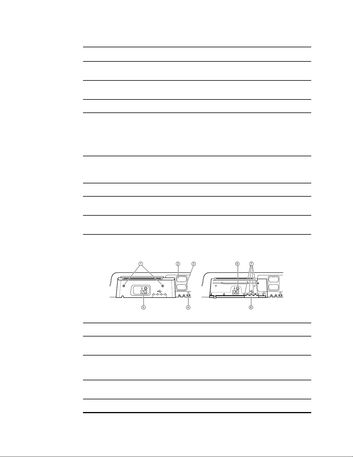
Front underside views
(Left: USB/Comms cover attached; Right: USB/Comms cover removed)
1 Retention screws Supports removing and attaching USB/Comms cover.
2 Blood pressure Self-contained module for easy replacement. Supports
dual-lumen or single-lumen hoses.
3 Pulse oximetry Optional Nellcor (SpO2) or Masimo Rainbow SET (SpO2 or
combined SpO2/SpHb) in a self-contained module for easy
replacement.
4 USB-to-computer connector Provides a connection to an external computer for testing,
data transfer, and software upgrades.
5 Power connection Provides an external AC power connection.
14 Controls, indicators, and connectors Welch Allyn Connex
®
Integrated Wall System
No. Feature Description
6 Ground lug (equipotential terminal) Supports electrical safety testing; terminal for connecting a
potential equalization conductor.
7 USB connectors Provides access to host USB connections for optional
accessories.
8 USB cable retainer Reduces strain on USB cables and connectors; helps
prevent cables from disconnecting.
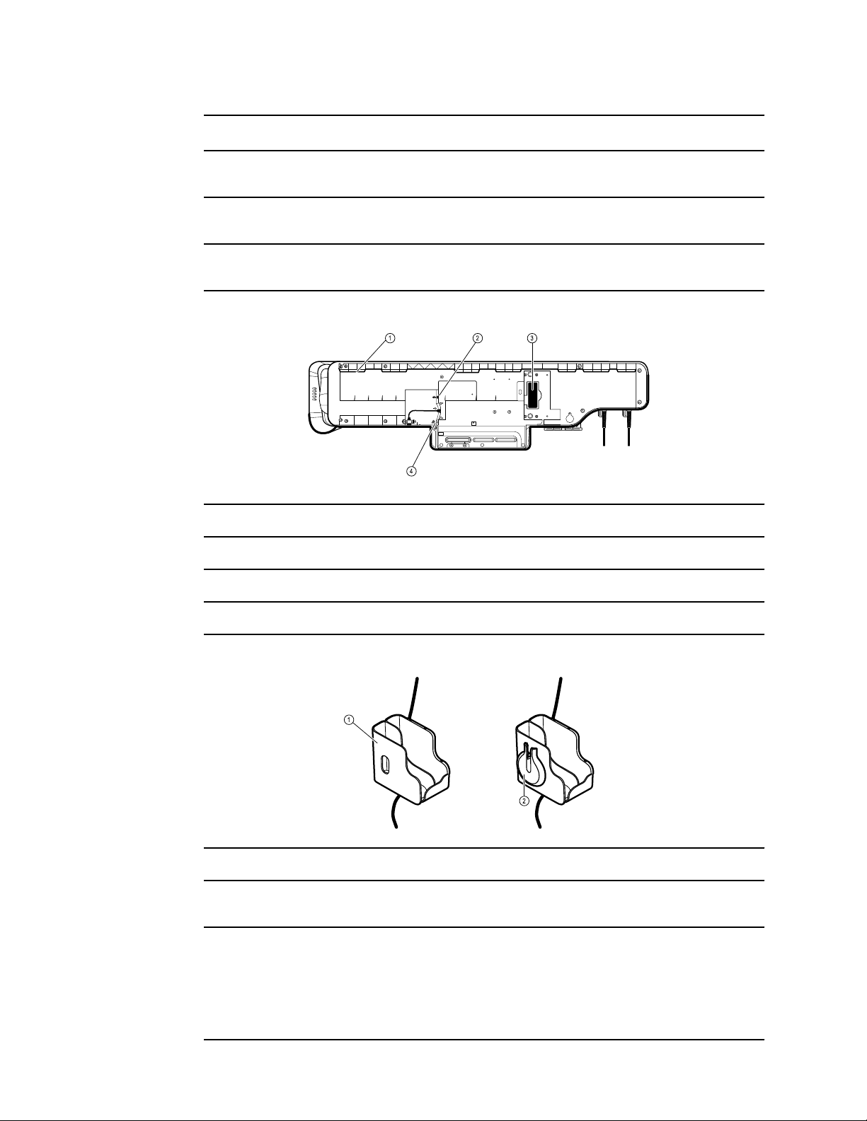
Back view
1 Recess for mounting bracket Secures the monitor when mounted on the wall.
2 Ethernet RJ-45 Provides a hardwired connection to the computer network.
3 Li-ion battery Provides backup power to wall system.
4 Nurse call Provides a connection to the hospital nurse call system.
Accessory bin
1 Accessory bin Stores accessories and organizes cables.
2 SpO2 holder Provides location to wrap SpO2 cable and attach SpO2
finger clip.
Directions for use Controls, indicators, and connectors 15
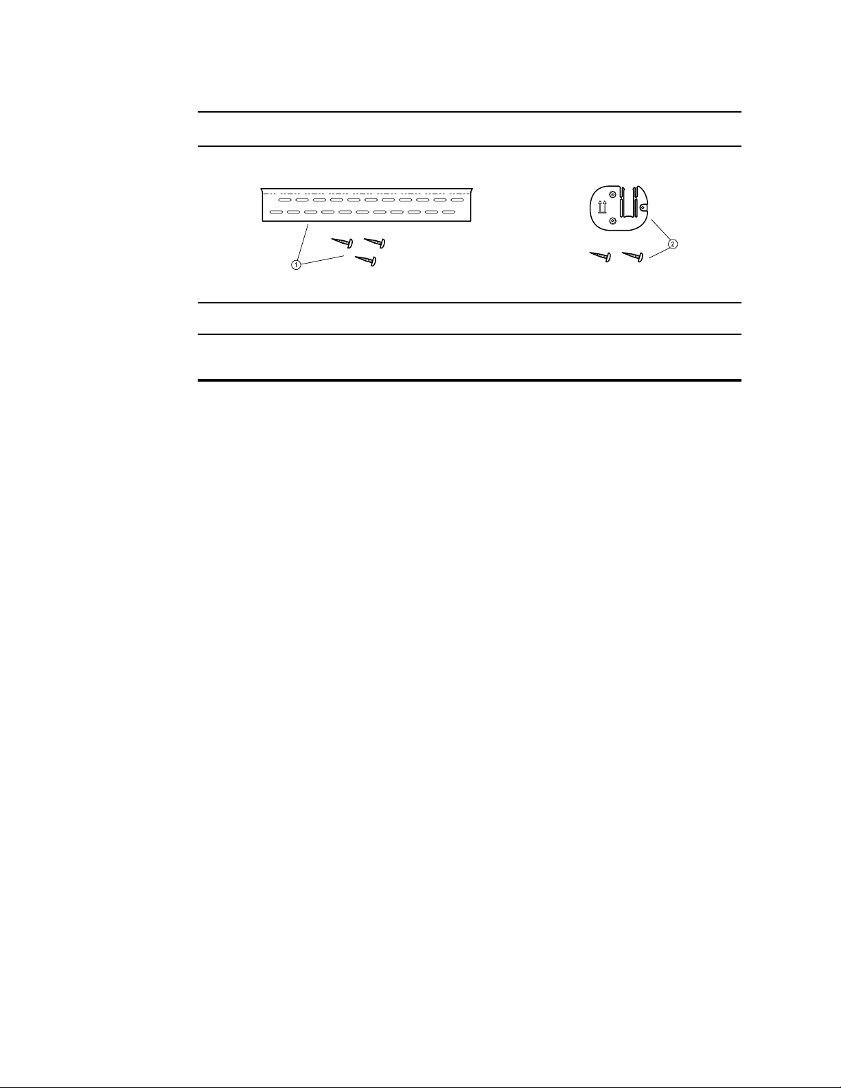
No. Feature Description
Mounting materials
1 Wall mounting rail bracket and hardware Secures the wall system to the wall.
2 Accessory bin mounting bracket and
hardware
Secures accessory bin to the wall and provides routing and
strain relief for power cord.
16 Controls, indicators, and connectors Welch Allyn Connex
®
Integrated Wall System
Setup
CAUTION Welch Allyn is not responsible for the integrity of any wall mounting
interface. Welch Allyn recommends that you contact your Biomedical Engineering
Department or maintenance service to ensure professional installation, safety, and
reliability of any mounting accessory.
Supplies and accessories
For a list of all approved supplies and accessories, see Approved Accessories in the Appendix.
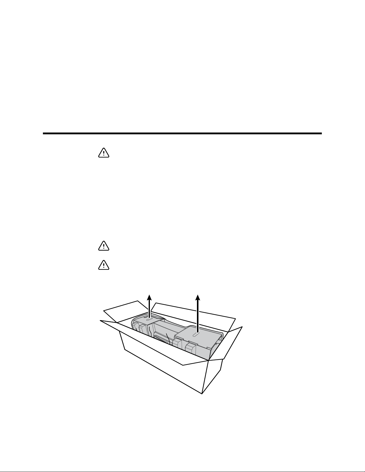
Unpack the wall system
This procedure applies to first-time setup of the wall system.
CAUTION You must follow these instructions exactly to ensure safety and ease of
assembly.
CAUTION Do not remove any packing materials around the wall system until the
instructions tell you to do so.
1. Lift the wall system out of the box by the cardboard handles.
2. With the wall system still in its packing material, place it onto a table or flat work surface and
remove it from the plastic bag.
17
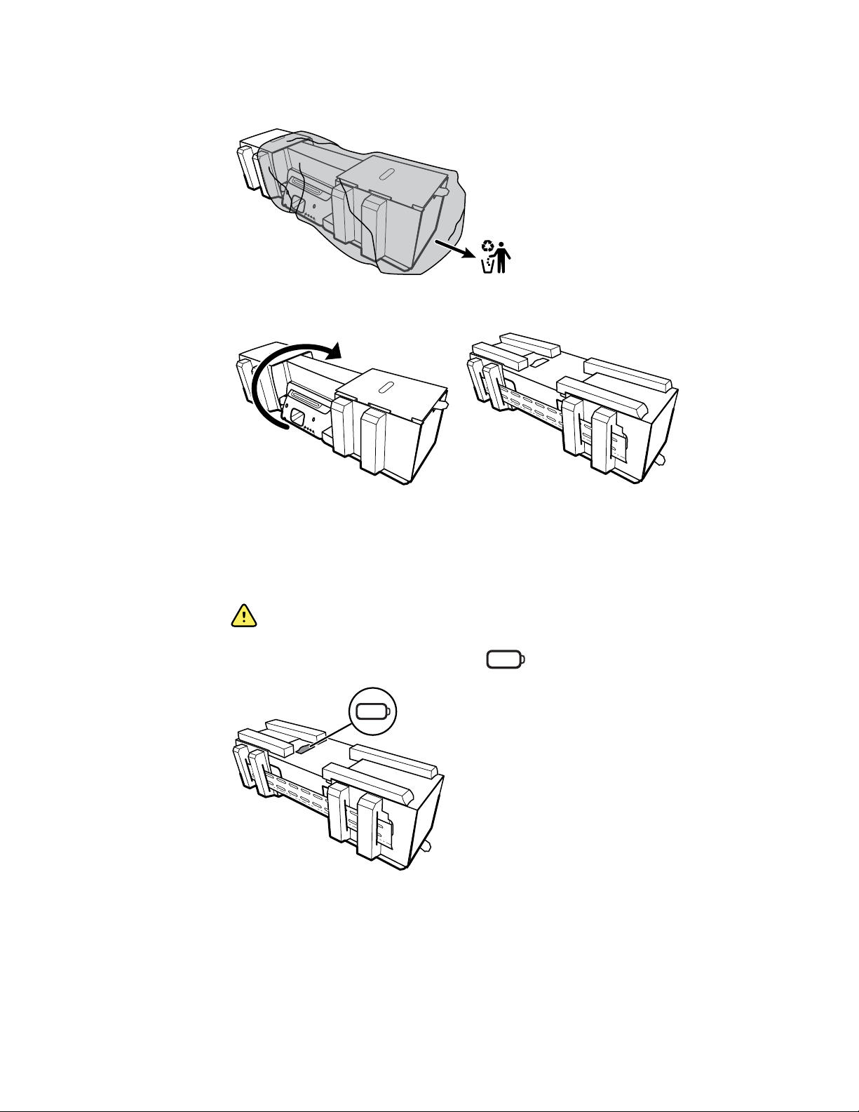
3. Turn the wall system over so that back of the wall system faces up.
Insert the battery
This procedure applies to first-time setup of the wall system. Therefore, the wall system is
assumed to be shut down.
WARNING Risk of fire, explosion, and burns. Do not short-circuit, crush,
incinerate, or disassemble the battery pack.
1. Locate the battery compartment, indicated by .
2. Insert the battery. (The battery is in a pink anti-static bag in the accessory box.)
18 Setup Welch Allyn Connex
®
Integrated Wall System

Prepare for mounting
1. Slide the mounting rail bracket out of the packing material and put it aside. Do not discard.
Then flip the wall system onto its back.
1
2
2. Remove the cardboard end caps and all foam as shown and put aside for recycling.
Directions for use Setup 19
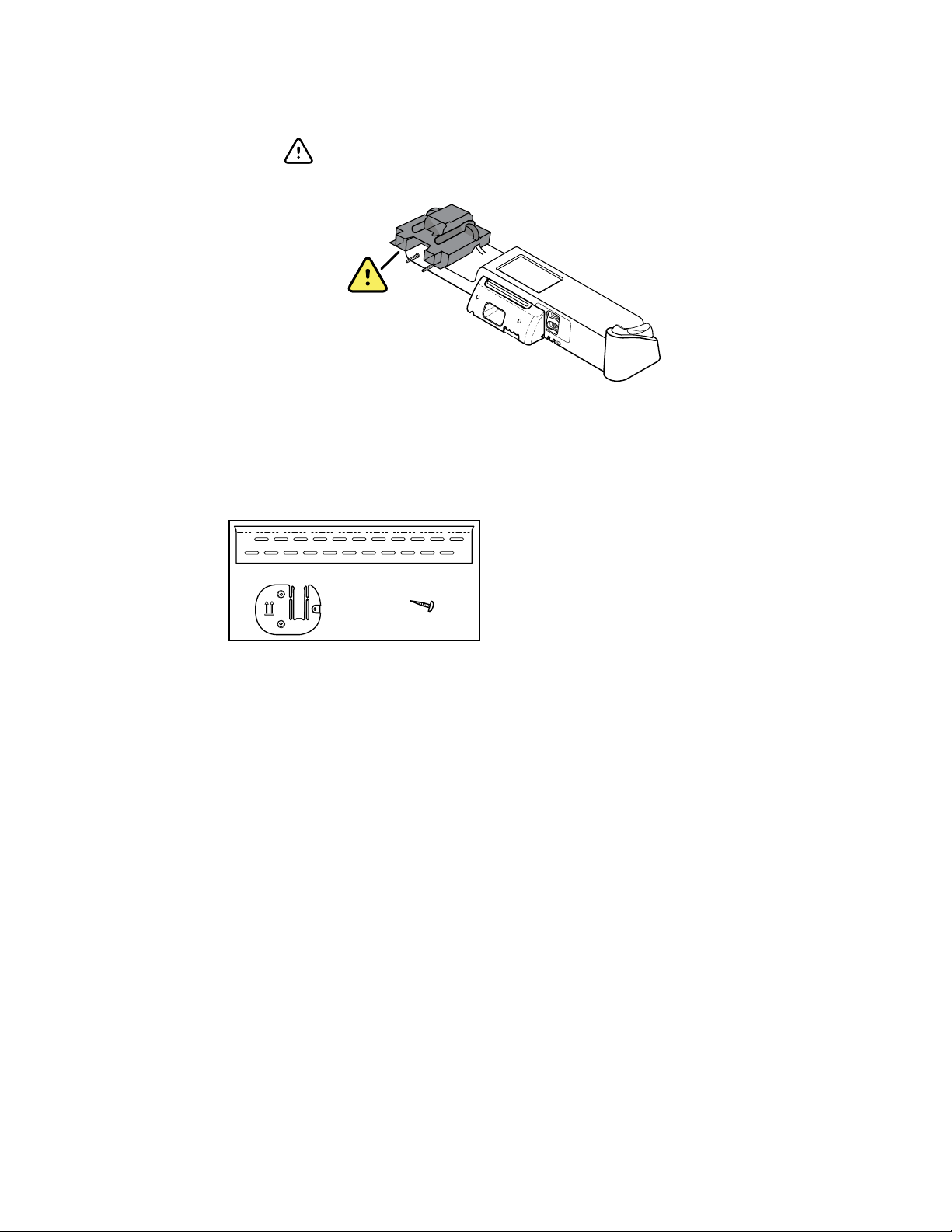
CAUTION Do not remove the cardboard securing the handles on
the left side of the wall system at this time. The cardboard prevents
damage to those instruments during the mounting process.
Mounting hardware inventory
Use these items to mount the wall system.
6 x
• Mounting rail bracket
• Accessory bin bracket
• Screws
Tools list
Use these tools to mount the wall system.
•
#2 Phillips screwdriver
• level
• tape measure
• stud finder
• drill
• 1/8-inch (3.17 mm) diameter drill bit
Mounting location
Before mounting the wall system, consider the following recommendations to determine the best
mounting location:
•
Mount the wall system to studs.
• Mount the wall system within reach of the AC power outlet. The power cord is 8 ft. (2.44 m)
long.
• Avoid brightly lit areas.
• Blood pressure tubing is 8 ft. (2.44 m) long.
20 Setup Welch Allyn Connex
®
Integrated Wall System
• Position the wall system so that all instruments are accessible and in a location that allows for
ergonomic examinations.
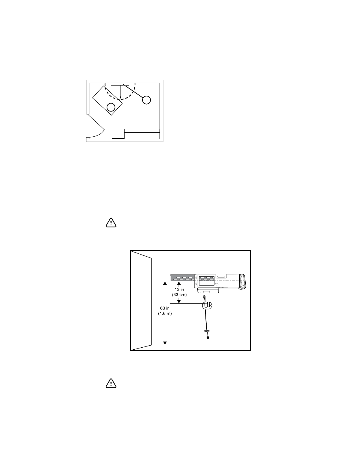
Sample room layout
1
2
r
1.
Connex Integrated Wall System
2.
Examination table
Mount the wall system
1. On the selected wall, find and mark the studs, and choose the system height and
corresponding height for the mounting rail bracket.
Recommendation: Place the mounting rail bracket 63 in. (1.6 m) from the floor, which
places screen center height at approximately 63 in. (1.6 m) from the floor.
CAUTION This drawing shows the physical relationships of the
mounting brackets to each other and to the wall system after you
complete the mounting instructions. Do not place the wall system
on the wall until you have completed all preliminary steps.
2. Affix the mounting rail bracket to three studs at the selected height using the available screws
(anchors are provided for additional support).
CAUTION Ensure that the upper "lip" of the bracket sticks out
from the wall and that the bracket is level.
Directions for use Setup 21
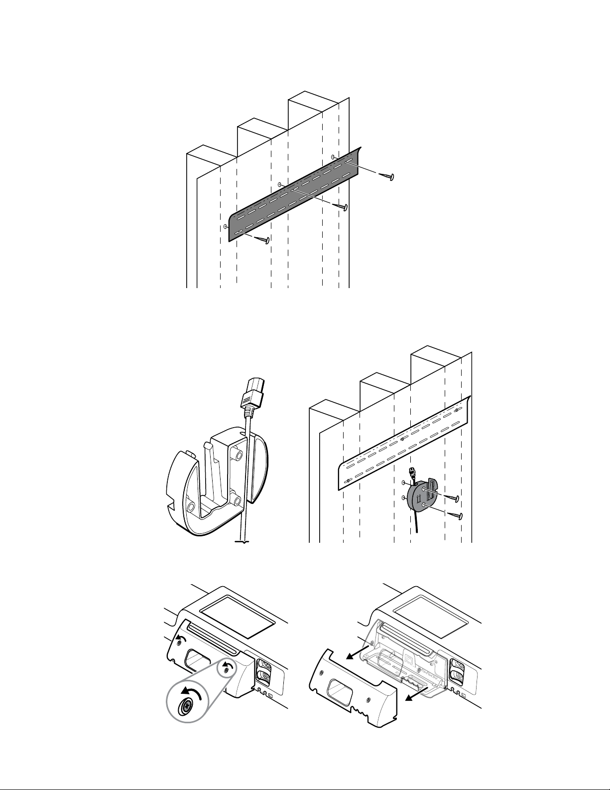
3. Route the power cord through the channel in the back of the accessory bin bracket, then
mount the bracket on the center stud at least 13 in. (33 cm) below the mounting rail bracket.
4. Before mounting the wall system, remove the cover by loosening the captive retention screws.
22 Setup Welch Allyn Connex
®
Integrated Wall System

5. Hang wall system on the mounting rail bracket.
WARNING Ensure that the ribs on the back of the wall system
fully engage the mounting rail bracket. The wall system should be
level and flush to the wall.
6. Select one of the three available slots at the bottom of the unit that overlaps a stud, and
secure the unit to the stud with the remaining screw.
WARNING Failure to install this security screw may result in
personal injury and equipment damage.
Directions for use Setup 23
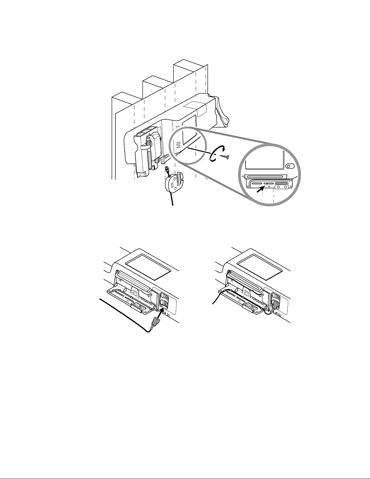
7. If the wall unit is configured for SpO2 or SpHb, connect the sensor cable and route it through
the channel above the security screw you just installed.
8. Re-attach the cover.
a. Thread the sensor cable through the cutouts on the top right and bottom left of the cover.
24 Setup Welch Allyn Connex
®
Integrated Wall System
Loading...