


 Loading...
Vital Signs Monitor
300 Series
Service Manual
Software version 1.2X

ii |
Welch Allyn Vital Signs Monitor 300 Series |
Copyright Welch Allyn. All rights are reserved. No one is permitted to reproduce or duplicate, in any form, this manual or any part thereof without permission from Welch Allyn.
Welch Allyn assumes no responsibility for any injury to anyone, or for any illegal or improper use of the product, that may result from failure to use this product in accordance with the instructions, cautions, warnings, or statement of intended use published in this manual.
Welch Allyn® and Flexible Monitoring® are registered trademarks of Welch Allyn. POEM™ and FlexNet™ are trademarks of Welch Allyn.
Nellcor® and Oximax® are registered trademarks of Nellcor Puritan Bennett.
SET®, LNCS®, and Masimo® are registered trademarks of Masimo Corporation. Possession or purchase of a Masimo SpO2- equipped monitor does not convey any express or implied license to use the device with unauthorized sensors or cables which would, alone or in combination with this device, fall within the scope of one or more of the patents relating to this device.
Software in this product is copyright by Welch Allyn or its vendors. All rights are reserved. The software is protected by United States of America copyright laws and international treaty provisions applicable worldwide. Under such laws, the licensee is entitled to use the copy of the software incorporated with this instrument as intended in the operation of the product in which it is embedded. The software may not be copied, decompiled, reverse-engineered, disassembled or otherwise reduced to human-perceivable form. This is not a sale of the software or any copy of the software; all right, title and ownership of the software remain with Welch Allyn or its vendors.
For information about any Welch Allyn product, call the nearest Welch Allyn representative:
USA |
1 |
800 535 6663 |
Australia |
+ 6129 638 3000 |
|
+ 1 315 685 4560 |
|
800 074 793 |
|
Canada |
1 |
800 561 8797 |
China |
+ 86 216 327 9631 |
European Call Center |
+ 353 46 906 7790 |
France |
+ 331 6009 3366 |
|
Germany |
+ 49 747 792 7186 |
Japan |
+ 8133 219 0071 |
|
Latin America |
+ 1 305 669 9003 |
Netherlands |
+ 3115 750 5000 |
|
Singapore |
+ 656 419 8100 |
South Africa |
+ 2711 777 7555 |
|
United Kingdom |
+ 44 207 365 6780 |
Sweden |
+ 46 85 853 6551 |
|
This device complies with Part 15 of the FCC rules and with the rules of the Canadian ICES-003. Operation is subject to the following two conditions: (1) This device may not cause harmful interference and (2) this device must accept any interference received, including interference that may cause undesired operation.
Caution! Changes or modifications not expressly approved by Welch Allyn could void the purchaser’s authority to operate the equipment.
Reorder Part Number 810-2811-XX (CD, English)
Reorder Part Number 810-2812-XX (printed, English)
Manual Part Number 810-1651-02 Rev A, Jan 08
|
Welch Allyn Ltd |
Welch Allyn, Inc. |
Navan Business Park |
8500 SW Creekside Place |
Dublin Road, Navan |
Beaverton, OR 97008-7107 USA |
County Meath, Republic of Ireland |
www.welchallyn.com
Printed in USA

iii
Contents
1 - Safety . . . . . . . . . . . . . . . . . . . . . . . . . . . . . . . . . . . . . . . . . . . . . . . . . . 1
General safety considerations . . . . . . . . . . . . . . . . . . . . . . . . . . . . . . . . . . . . . . . 1 Electrostatic discharge (ESD) . . . . . . . . . . . . . . . . . . . . . . . . . . . . . . . . . . . . . . . . 2 Symbols . . . . . . . . . . . . . . . . . . . . . . . . . . . . . . . . . . . . . . . . . . . . . . . . . . . . . . . . 3
2 - Service overview . . . . . . . . . . . . . . . . . . . . . . . . . . . . . . . . . . . . . . . . . 5
Purpose and scope . . . . . . . . . . . . . . . . . . . . . . . . . . . . . . . . . . . . . . . . . . . . . . . . 5 Technical support services . . . . . . . . . . . . . . . . . . . . . . . . . . . . . . . . . . . . . . . . . . 5 Returning products . . . . . . . . . . . . . . . . . . . . . . . . . . . . . . . . . . . . . . . . . . . . . . . . 6 Product configurations . . . . . . . . . . . . . . . . . . . . . . . . . . . . . . . . . . . . . . . . . . . . . 6 Recommended service intervals . . . . . . . . . . . . . . . . . . . . . . . . . . . . . . . . . . . . . 7 Service options . . . . . . . . . . . . . . . . . . . . . . . . . . . . . . . . . . . . . . . . . . . . . . . . . . . 7 Related documents. . . . . . . . . . . . . . . . . . . . . . . . . . . . . . . . . . . . . . . . . . . . . . . . 7 Service menu . . . . . . . . . . . . . . . . . . . . . . . . . . . . . . . . . . . . . . . . . . . . . . . . . . . . 8
3 - Functional verification . . . . . . . . . . . . . . . . . . . . . . . . . . . . . . . . . . . . 9
Functional verification overview . . . . . . . . . . . . . . . . . . . . . . . . . . . . . . . . . . . . . . 9 Equipment required . . . . . . . . . . . . . . . . . . . . . . . . . . . . . . . . . . . . . . . . . . . . . . . 9 Functional verification procedure . . . . . . . . . . . . . . . . . . . . . . . . . . . . . . . . . . . . 11 Checklist and test results report form . . . . . . . . . . . . . . . . . . . . . . . . . . . . . . . . 30
4 - Troubleshooting and repair . . . . . . . . . . . . . . . . . . . . . . . . . . . . . . . 33
Troubleshooting chart . . . . . . . . . . . . . . . . . . . . . . . . . . . . . . . . . . . . . . . . . . . . . 33 Requirements for module-level repair and replacement. . . . . . . . . . . . . . . . . . . 35 NIBP characterization . . . . . . . . . . . . . . . . . . . . . . . . . . . . . . . . . . . . . . . . . . . . . 35 Welch Allyn monitor service utility . . . . . . . . . . . . . . . . . . . . . . . . . . . . . . . . . . . 36
5 - Disassembly procedure . . . . . . . . . . . . . . . . . . . . . . . . . . . . . . . . . . 53
Procedures overview . . . . . . . . . . . . . . . . . . . . . . . . . . . . . . . . . . . . . . . . . . . . . 53 Remove and disconnect the battery . . . . . . . . . . . . . . . . . . . . . . . . . . . . . . . . . . 56 Separate the front and rear chassis . . . . . . . . . . . . . . . . . . . . . . . . . . . . . . . . . . 57 Disassemble the front chassis assembly . . . . . . . . . . . . . . . . . . . . . . . . . . . . . . 58 Remove the LCD display from the main board. . . . . . . . . . . . . . . . . . . . . . . . . . 60 Disassemble the rear chassis assembly. . . . . . . . . . . . . . . . . . . . . . . . . . . . . . . 61 Remove the main board . . . . . . . . . . . . . . . . . . . . . . . . . . . . . . . . . . . . . . . . . . . 62 Disassemble and remove the NIBP assembly . . . . . . . . . . . . . . . . . . . . . . . . . . 65 Remove and disassemble the printer assembly . . . . . . . . . . . . . . . . . . . . . . . . . 68 Disassemble the temperature module . . . . . . . . . . . . . . . . . . . . . . . . . . . . . . . . 76 Disassemble the Nellcor SpO2 assembly . . . . . . . . . . . . . . . . . . . . . . . . . . . . . . 79 Disassemble the Masimo SpO2 assembly . . . . . . . . . . . . . . . . . . . . . . . . . . . . . 82
iv |
Contents |
Welch Allyn Vital Signs Monitor 300 Series |
6 - Replacement parts . . . . . . . . . . . . . . . . . . . . . . . . . . . . . . . . . . . . . . 85
7 - Updates and service bulletins . . . . . . . . . . . . . . . . . . . . . . . . . . . . . 95
DC power cable clamp . . . . . . . . . . . . . . . . . . . . . . . . . . . . . . . . . . . . . . . . . . . . 95
Index . . . . . . . . . . . . . . . . . . . . . . . . . . . . . . . . . . . . . . . . . . . . . . . . . . . . 97

1
1 Safety
All personnel must read and understand all safety information presented in this manual before using or repairing the monitor.
Caution Use only the Welch Allyn Monitor Service Utility (810-1784-XX) with this monitor.
Software service tools, such as the “Custom Repair Software” (part number 130S29E), distributed for use with previous models of the Vital Signs Monitor, must not be used with the Model 300 Series. Use of any tool other than the Welch Allyn Monitor Service Utility (810-1784-XX) may set the monitor in an undefined and unrecoverable state.
United States federal law restricts this device to sale, distribution, or use by or on the order of a licensed medical practitioner.
General safety considerations
Always consider the following safety points when using the monitor:
•Place the monitor and accessories in locations where they cannot harm the patient should they fall from a shelf or mount.
•Do not connect more than one patient to a monitor.
•Do not connect more than one monitor to a patient.
•Do not use the monitor in an MRI suite or hyperbaric chamber.
•Do not autoclave the monitor.
•Accessories can be autoclaved only if the manufacturer’s instructions clearly approve it. Many accessories can be severely damaged by autoclaving.
•Inspect the power adapter cord periodically for fraying or other damage. Replace the adapter as needed. Do not operate the monitor from mains power if the adapter, the adapter cord, or the cord plug is damaged.
•Frequently check all cables, both electrically and visually.
•To avoid explosion, do not operate the monitor in the presence of flammable anesthetics.
•To ensure patient safety, use only accessories recommended or supplied by Welch Allyn. (See Products and Accessories, part number 810-0409-XX.) Always use accessories according to your facility’s standards and according to the manufacturer’s recommendations and instructions. Always follow the manufacturer’s directions for use.
2 |
Safety |
Welch Allyn Vital Signs Monitor 300 Series |
•A monitor that has been dropped or otherwise damaged or abused must not be used until it has been tested and verified by qualified service personnel for proper operation.
•If the monitor detects an unrecoverable problem, an error code and a brief message appear in the message display. Report all such errors to Welch Allyn.
•While under warranty, the monitor must be serviced only by a Welch Allyn service technician.
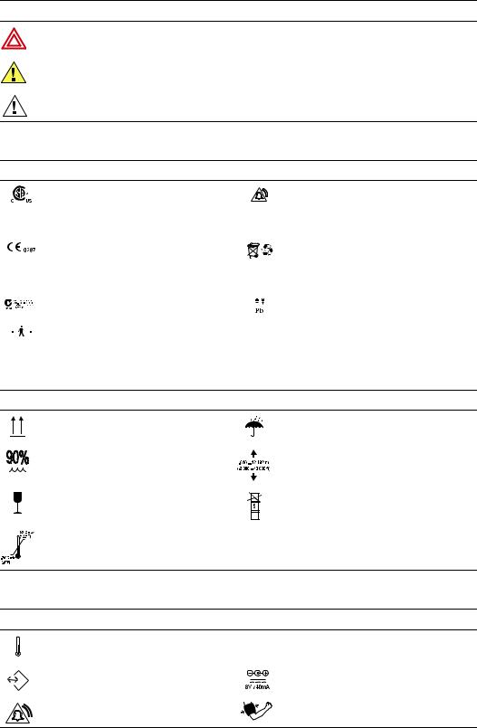
Electrostatic discharge (ESD)
CAUTION
SENSITIVE ELECTRONIC DEVICES
DO NOT SHIP OR STORE NEAR STRONG ELECTROSTATIC, ELECTROMAGNETIC, MAGNETIC OR RADIOACTIVE FIELDS.
ATTENTION
OBSERVE PRECAUTIONS
FOR HANDLING
ELECTROSTATIC
SENSITIVE DEVICES
WARNING Electrostatic discharge (ESD) can damage or destroy electronic components. Handle static-sensitive components only at static-safe workstation.
WARNING Consider all electrical and electronic components of the monitor as static-sensitive.
Electrostatic discharge is a sudden current flowing from a charged object to another object or to ground. Electrostatic charges can accumulate on common items such as foam drinking cups, cellophane tape, synthetic clothing, untreated foam packaging material, untreated plastic bags, and work folders, to name only a few.
Electronic components and assemblies, if not properly protected against ESD, can be permanently damaged or destroyed when near or in contact with electrostatically charged objects. When you handle components or assemblies that are not in protective bags and you are not sure whether they are static-sensitive, assume that they are static-sensitive and handle them accordingly.
•Perform all service procedures in a static-protected environment. Always use techniques and equipment designed to protect personnel and equipment from electrostatic discharge.
•Remove static-sensitive components and assemblies from their static-shielding bags only at static-safe workstations—a properly grounded table and grounded floor mat— and only when you are wearing a grounded wrist strap (with a resistor of at least 1 megohm in series) or other grounding device.
•Use only grounded tools when inserting, adjusting, or removing static-sensitive components and assemblies.
•Remove or insert static-sensitive components and assemblies only with monitor power turned off.
•Insert and seal static-sensitive components and assemblies into their original staticshielding bags before removing them from static-protected areas.
•Always test your ground strap, bench mat, conductive work surface, and ground cord before removing components and assemblies from their protective bags and before beginning any disassembly or assembly procedures.
Service manual |
Safety |
3 |
Symbols
The symbols illustrated on the following pages appear on the monitor or in this document.
Documentation symbols
WARNING Indicates conditions that could lead to illness, injury, or death.
Caution In this manual, indicates conditions that could damage equipment or other property.
Caution On the product, means “Consult accompanying documentation.”
Certification and operation labels
This device has been tested and certified by the Canadian Standards Association International to comply with applicable U.S. and Canadian medical safety standards.
Urgent alarm notification (output to Nurse Call system)
|
|
|
|
The CE Mark and Notified Body Registration |
|
Recycle used batteries properly and in accordance |
|
|
|
|
Number signify that the device meets all essential |
|
with local regulations. |
|
|
|
|
requirements of the European Medical Device |
|
Do not dispose of batteries in refuse containers. |
|
|
|
|
Directive 93/42/EEC. |
|
|
|
|
|
|
Australian Registered Importer |
|
Sealed lead-acid battery, 6V 4 Ah |
|
||||||
|
|
|
|
Patient connections are Type BF, and protected |
|
|
|
|
|
|
|
||
|
|
|
|
against defibrillation. |
|
|
|
|
|
|
|||
|
|
|
|
|
|
|
Shipping, storing, and environment labels
Keep this end of the package or shipping crate up. |
Protect the monitor from exposure to rain. |
Do not expose the monitor to relative humidity above this limit.
Do not subject the monitor to altitudes outside these limits.
Fragile contents—handle with care. |
|
Limit stacking to this number of units. |
|
|
|
|
|
|
Do not expose the monitor to temperatures |
outside these limits. |
Monitor connector labels
Temperature Probe Cable Connector |
SpO2 |
SpO2 Sensor Cable Connector |
RS232 Cable Connector |
|
AC Power Adapter Cable Connector |
Nurse Call Cable Connector |
|
NIBP Hose Connector |
4 |
Safety |
Welch Allyn Vital Signs Monitor 300 Series |
Printer door label
Press to open the printer door |
Load paper this direction |
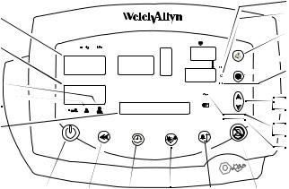
The monitor front panel controls are described in more detail throughout this document.
Front panel controls
Set alarm limits |
Power on/off |
Silence alarms |
Print patient data |
Scroll up/down, Scroll forward/back, |
Review patient data |
Increase/decrease value |
|
(The scroll icon appears as these two arrows in the documentation.)
Set an NIBP automatic measurement interval
Cycle to the next menu selections
Start/stop an NIBP cycle (AUTO button)
Front panel displays and indicators
SYS |
Systolic pressure |
|
Temperature |
DIA |
Diastolic pressure |
|
|
SpO2 |
Arterial hemoglobin oxygen saturation |
|
|
|
Pulse rate |
pulse |
Pulse strength |
|
|
amplitude |
|
|
|
indicator |
|
message |
MAP (mean arterial pressure) |
|
Neonatal |
window |
|
|
|
ºC |
Degrees Celsius |
|
Pediatric |
ºF |
Degrees Fahrenheit |
|
Adult |
|
|
|
|
M |
Monitored temperature |
|
AC power |
|
|
Battery charging (flashing) |
|
|
|
Battery charged (steady) |
|
|
Battery low |
|
|
|
Battery fully discharged |
|
|

5
2 Service overview
Purpose and scope
This service manual is a reference for periodic preventive maintenance and corrective service procedures for the Vital Signs Monitor 300 Series.
Corrective service is supported to the level of field-replaceable units. These include some circuit-board assemblies and some subassemblies, case parts, and other parts. (See “Replacement parts” on page 85 for a complete list of user-replaceable service parts.)
Note Repair and replacement of the main board is not supported. All service work on the main board must be performed by certified and qualified service personnel at an authorized Welch Allyn service center.
Caution No component-level repair of circuit boards and subassemblies is supported. Use only the repair procedures described in this manual.
WARNING When performing a service procedure, follow the instructions exactly as presented in this manual. Failure to do so could damage the monitor, invalidate the product warranty, and lead to serious personal injury.
This guide provides troubleshooting information, assembly procedures, and instructions for functional testing and performance verification. It is intended for use only by technically qualified service personnel.
This guide applies only to the Vital Signs Model 300 Series. For servicing the previous (52000-series) version of the Vital Signs Monitor, refer to Welch Allyn service manual 95P445E, which is available on the TechView CD (900298-1).
Technical support services
Welch Allyn offers the following technical support services:
Telephone support
Loaner equipment
Service agreements
Service training
Replacement service parts
Factory Service
For information on any of these services, contact Welch Allyn at the customer-service numbers listed on page ii.

6 |
Service overview |
Welch Allyn VSM 300 Series |
Returning products
To return a product for service, contact Welch Allyn Technical Support and request a Return Material Authorization (RMA) number.
Note Welch Allyn does not accept returned products without an RMA.
When requesting an RMA, please have the following information available:
•Product name, model number, and serial number
•A complete return shipping address, including a contact name and phone number; include any special shipping instructions
•A purchase-order number or credit-card number if the product is not covered by warranty
•A full description of the problem or service request
To ship the monitor, please observe these packing guidelines:
•Remove from the package all hoses, connectors, cables, sensors, power cords, and other ancillary products and equipment, except those items that might be associated with the problem.
•Use the original shipping carton and packing materials, or as close an approximation as possible.
•Include a packing list.
•Write the Welch Allyn RMA number with the Welch Allyn address on the outside of the shipping carton.
United States federal regulations require that any unit received by Factory Service must be free from blood-borne pathogens before processing. All incoming products are cleaned as well as possible, but products that cannot be effectively cleaned cannot be accepted for repair. Please thoroughly clean all organic residues from the product before shipment. This will ensure safe receipt, processing and repair, and will help expedite the return of your monitor.
Product configurations
Model numbers for the configurations are as follows:
Model |
Features |
|
Model |
Features |
|
|
|
|
|
|
|
53000 |
Standard (NIBP, Pulse Rate, and MAP) |
530T0 |
Standard + Temperature |
|
|
5300P |
Standard + Printer |
|
530TP |
Standard + Temperature + Printer |
|
53N00 |
Standard + Nellcor® SpO |
2 |
53S00 |
Standard + Masimo® SpO |
|
|
|
|
|
2 |
|
53NT0 |
Standard + Nellcor SpO2 + Temperature |
53ST0 |
Standard + Masimo SpO2 + Temperature |
||
53N0P |
Standard + Nellcor SpO2 + Printer |
53S0P |
Standard + Masimo SpO2 |
+ Printer |
|
53NTP |
Standard + Nellcor SpO2 + Temperature + Printer |
53STP |
Standard + Masimo SpO2 |
+ Temperature + Printer |
|
|
|
|
|
|
|
Service manual Service overview 7
Recommended service intervals
Interval or Condition |
Action Recommended |
Procedure |
Page |
|
|
|
|
Every 6 - 24 months |
Complete functional test |
Functional verification |
9 |
(per hospital protocols) |
|
|
|
Battery does not hold a charge |
Check battery capacity |
Functional verification |
9 |
|
Replace battery |
Disassembly procedure |
53 |
Monitor has been dropped or |
Complete functional test |
Functional verification |
9 |
otherwise damaged |
|
|
|
Monitor malfunctioning |
Complete functional test |
Functional verification |
9 |
Monitor does not pass |
Troubleshooting and repair followed by |
Troubleshooting and repair |
33 |
Functional Verification |
functional test; if necessary, return to |
Disassembly procedure |
53 |
|
authorized service center |
Functional verification |
9 |
|
|
|
|
Service options
Warranty service
All repairs on products under warranty must be performed or approved by Welch Allyn. Refer all warranty service to Welch Allyn Factory Service or another authorized Welch Allyn Service Center. Obtain an RMA number for all returns to Welch Allyn Factory Service – see “Returning products” on page 6.
Caution Unauthorized repairs will void the product warranty.
Non-warranty service
Welch Allyn Factory Service and authorized Service Centers support non-warranty repairs. Contact any Welch Allyn regional service center for pricing and service options.
Welch Allyn offers modular repair parts for sale to support non-warranty service. This service must be performed only by qualified end-user biomedical/clinical engineers using this service manual.
The Welch Allyn Monitor Service Utility supports certain service functions. For information, see “Welch Allyn monitor service utility” on page 36.
Related documents
Title |
|
Reorder number |
Vital Signs Monitor 300 |
Series Directions for Use (Masimo, multilanguage) |
810-2250-XX |
Vital Signs Monitor 300 |
Series Directions for Use (Nellcor, multilanguage) |
810-2252-XX |
Welch Allyn Parts and Accessories Guide |
810-0409-XX |
|
8 |
Service overview |
Welch Allyn VSM 300 Series |
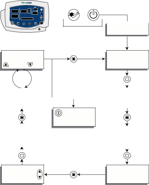
Service menu
To see the service menu, first power the monitor off. Press and hold 
 for 3 seconds. While
  is depressed, press
  until the monitor displays the message Service Mode. The monitor runs a self-test and then displays the main software version number (M: 1.00.00). Press
  repeatedly to cycle to the menu selection of interest.
/min
SYS |
SpO2 % |
DIA (mmHg)
3 seconds  SERVICE MODE
Power-up Self-test
RESET TO DEFAULT |
Main SW version |
|
M: X.XX.XX |
YES |
NO |
|
|
|
|
|
|
|
|
|
|
|
|
|
|
|
|
|
|
|
|
|
|
|
|
|
|
|
|
|
|
|
|
|
|
|
|
|
BP CYCLES:XXXXXX |
|
|
|
|
NIBP SW version |
|
|
|
|
|
|
|
|
|||
|
|
|
|
|
N:XX.XX.XX |
|
||
|
RUN TIME:XXXXX |
|
|
|
|
|
||
|
|
|
|
|
|
|
|
|
|
|
|
|
|
|
|
|
|
|
|
|
|
|
|
|
|
|
POWER OFF
Exit Service Mode
|
|
|
|
|
|
|
|
|
|
BATTERY:X.XX V |
|
|
|
SpO2 SW version |
|
||
|
|
|
|
|
||||
|
|
|
|
S:X.X.X.X |
|
|||
|
|
|
|
|
|
|
|
|
|
|
|
|
|
|
|
|
|
|
|
|
|
|
|
|
|
|
|
|
|
|
|
|
|
|
|
|
|
|
|
|
|
|
|
|
|
|
|
|
|
|
|
|
|
|
|
|
|
|
|
|
|
|
NIBP TEST
Temperature SW version
T:X.X

9
3 Functional verification
Functional verification overview
This section describes the procedure for a complete functional test to support recommended preventive-maintenance schedules.
The verification includes tests for a monitor configured with the printer, temperature, and SpO2 options. Perform only the tests applicable to the actual configuration.
A checklist of the functional tests is provided on “Checklist and test results report form” on page 30. It is recommended that you print a copy of the checklist each time you perform the functional verification procedure, so that you can record and save the test results. If the monitor ever requires service, the records of test results can often facilitate troubleshooting.
Functional verification does not require opening the monitor case.
Equipment required
This equipment is required for functional verification of a fully configured monitor.
Commercially available general-purpose/medical test equipment
Item |
Manufacturer part number/specification |
|
|
Power supply |
Variable, 0-8 VDC, 0.75 amperes (minimum), with voltage and current |
|
indicators (for 1mA current measurement) |
Digital pressure meter |
Netech Digimano 1000 or equivalent |
AC withstand voltage (hi-pot) tester |
Associated Research 3605 or equivalent |
SpO2 functional tester (Nellcor, for testing |
Nellcor SRC-MAX |
the monitor only) |
|
SpO2 functional tester (Masimo, for testing |
Masimo Tester REF 1593 |
the monitor only) |
|
SpO2 extension cable (required for SRC- |
Nellcor DEC-8 |
MAX) |
|
SpO2 simulator (for testing the monitor and |
Fluke (Biotek) Index2 XL/XLFE or equivalent |
the SpO2 sensor) |
|
Syringe, 60 mL, Slip tip, Luer |
BD (Becton, Dickinson) 309654 or equivalent |
Hi-pot cable connectors |
See “Hi-pot test connections” on page 29. |
Timer (to display elapsed time, in seconds) |
|
|
|

10 |
Functional verification |
Welch Allyn VSM 300 Series |
Welch Allyn accessories and test equipment
Temperature test key |
06138-000 |
(for testing the monitor only) |
|
9600 Temperature calibration tester |
01800-210, 110 V |
(for testing the monitor and the temperature probe) |
01800-500, 220 V |
|
01800-810, 220 V UK |
|
01800-910, 220 V Australia |
Neonatal cuff hose, 96-inch |
008-0265-XX |
Neonatal #1 cuff, disposable, box of 10 |
008-0620-XX |
Cuff simulator |
020-0702-XX |
DC power adapter |
5200-101A |
Battery substitution connector |
660-0237-00 |
(Use the female end from the cable set) |
|
Welch Allyn Monitor Service Utility |
810-1784-XX |
(required for NIBP repair or replacement; |
|
not required for functional testing) |
|
Service Serial Cable (for use with the Welch Allyn |
008-0842-XX |
Monitor Service Utility 810-1784-XX) |
|
Tycos air release valve and small bulb |
WA 5088-01 |
NIBP tubing connector, threaded |
600-0021-XX |
tubing, 1’ |
600-0179-XX |
Tee, plastic |
600-0043-XX |
|
|
Service manual |
Functional verification |
11 |
Functional verification procedure
Reference illustration
Systolic  window
Diastolic 
window
Adult 
Pediatric 
Neonatal 
Message 

window
|
|
Fahrenheit |
|
|
Celsius |
|
|
Print patient data |
|
|
/min |
SYS |
SpO2 % |
Change settings |
|
|
Monitored |
DIA |
|
temperature |
|
|
Increase/Decrease |
|
|
Forward/Back |
|
|
Battery charged |
|
|
Battery charging |
|
|
Battery low |
|
|
|
|
|
|
|
|
|
|
|
|
|
|
|
|
|
|
|
|
|
|
|
|
|
|
|
|
|
|
|
|
|
|
|
|
|
|
|
|
|
|
|
|
|
|
|
|
|
|
|
|
|
|
|
|
|
|
|
|
|
|
|
|
|
|
|
|
|
|
|
|
|
|
|
|
|
|
|
|
|
|
|
|
|
|
|
|
|
|
|
|
|
|
|
|
|
|
|
|
|
|
|
|
|
|
|
|
|
|
|
|
|
|
|
|
|
|
|
|
|
|
|
|
|
|
|
|
|
|
|
|
|
|
|
|
|
|
|
|
|
|
|
|
|
|
|
|
|
|
|
|
|
|
|
|
|
|
|
|
|
|
|
|
|
|
|
|
|
|
|
|
|
|
|
|
|
|
|
|
|
|
|
|
|
|
|
|
|
|
|
|
|
|
|
|
|
|
|
|
|
|
|
|
|
|
|
|
|
|
|
|
|
|
|
|
|
|
|
|
|
|
|
|
|
|
|
|
|
|
|
|
|
|
|
|
|
|
|
|
|
|
|
|
|
|
|
|
|
|
|
|
|
|
|
|
|
|
|
|
|
|
|
|
|
|
|
|
|
|
|
|
|
|
|
|
|
|
|
|
|
|
|
|
|
|
|
|
|
|
|
|
|
|
|
|
|
|
|
|
|
|
|
|
|
|
|
|
|
|
|
|
|
|
|
|
|
|
|
|
|
|
|
|
|
|
|
|
|
|
|
|
|
|
|
|
|
|
|
|
|
|
|
|
|
|
|
|
|
|
Power |
Review |
Set |
Start/ |
|
Set |
Silence |
||||||||||||||||||
On/Off |
patient |
NIBP |
stop |
alarm |
alarms |
|||||||||||||||||||
|
|
|
data |
interval |
NIBP |
limits |
|
|
|
|
||||||||||||||
System/power
Ct
Note Other than the optional NIBP overpressure test (page 18), the tests described here must be performed as part of a complete functional verification procedure.
Setup
•If the monitor is configured with the temperature option, connect the temperature probe and insert it into the probe well.
•If you are using the optional Welch Allyn Model 9600 Calibration Tester (01800-200), plug it in and set it to 96.4 °F (35.8 °C).
•If the monitor is configured with the SpO2 option, connect the SpO2 sensor.
Battery charge and beeper
1.With the monitor turned off, disconnect the power adapter from the monitor.
2.Verify that the charge LED  is off.
3.Connect the power adapter. The monitor emits a single beep tone.
4.Verify that the charge LED  is on.
Note Depending on the charge level of the battery, the charge LED may be either flashing or steady.
 flashing indicates that the monitor is running on AC, the battery is charging, and the battery is charged to less than 90% capacity.
 steady indicates that the monitor is running on AC, the battery may or may not be charging, and the battery is charged to at least 90% capacity.
12 |
Functional verification |
Welch Allyn VSM 300 Series |
Battery substitution cable setup
1.Disconnect the power adapter.
2.Remove the battery cover and remove and disconnect the battery.
3.Separate the connector pair (660-0237-00). Use the end that is identical to the connector on the battery as a battery substitution test cable.
4.Connect the open-ended red (+) and black (-) wires of this cable to the variable DC power supply.
5.Set the power supply to 6.0 V ± 50 mV.
6.Connect the test power cable to the battery connector on the monitor.
Monitor-off current
With the monitor powered down, verify that the current draw from the power supply is less than 1 mA.
Power-on self-test
1.Power the monitor on.
Note If the monitor displays error E38, power the monitor off and then power it on again.
2.Verify that the start-up tone (double beep) is audible.
3.Verify that all front-panel lights (background indicators, LCD pixels, and LED segments and periods) come on in the proper order: left, center, and right.
Initialization/idle mode current
Note If your monitor is configured without the temperature option and without the SpO2 option, skip these steps and proceed to “Baseline current draw” on page 13.
1.If the temperature option is present:
a.Verify that the temperature probe is in the probe well.
b.Set the temperature mode to MONITOR.
c.Remove the temperature probe from the probe well.
d.Verify that the temperature reading appears within 4 seconds.
e.Do not return the probe to the probe well.
2.If the SpO2 option is present:
a.Verify that the SpO2 sensor cable is connected to the monitor.
b.Verify that the current draw from the bench power supply is less than 800 mA.
3.Disconnect the SpO2 sensor (if equipped).
4.Insert the temperature probe (if the monitor is so equipped) into the probe well.
Service manual |
Functional verification |
13 |
Baseline current draw
1.With the monitor powered on, wait for the monitor LEDs to blank. In this state, the SpO2 % reads - -, the time of day is displayed in the message window, and the rest of the displays are blank.
2.Note and record the exact current from the power supply. (This value will be used in the NIBP and printer tests.)
Battery voltage
1.Power the monitor off.
2.Simultaneously press and hold 
 and
and  to bring up the monitor in SERVICE MODE. (When the monitor completes the power-on self-test in service mode, the main software version number appears in the message display.)
3.Press  repeatedly until BATTERY VOLTAGE appears in the message display.
4.Verify that the displayed battery voltage is within 0.1 volt of the DC power supply input.
5.Exit Service Mode by turning off the monitor and then turning it on again.
14 |
Functional verification |
Welch Allyn VSM 300 Series |
NIBP
Ct
Note The tests described in this section are to be performed only as part of a complete functional verification procedure.
Characterization test
1.Attach a neonate hose (part 008-0265-01) to the NIBP fitting on the monitor.
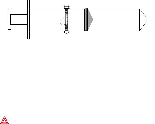
2.Prepare the 60-mL syringe as follows, with reference to the illustration below:
a.Move the syringe plunger to the 35 mL line.
b.Drill a small hole (for example, 9/64 inch) through the syringe and the plunger shaft, at a location between the plunger and the top of the syringe.
c.Insert a rod or bolt (for example, a 6-32 screw) through the hole so that the plunger cannot move, creating a constant volume in the syringe of 35 mL ± 2 mL. Secure the rod or bolt so that it cannot fall out of the hole.
-- |
-- |
-- |
-- |
-- |
-- |
-- |
-- |
-- |
-- |
-- |
-- |
60 |
|
50 |
|
40 |
|
30 |
|
20 |
|
10 |
|
ml |
|
|
|
|
|
|
|
|
|
|
|
3.Insert the tip of the syringe into the open end of the neonate hose. Verify that the fit is tight and secure.
4.Set the monitor patient type to Adult, as follows:
a. Press  once.
once.
b. If the monitor is not already in Adult mode, press  once or twice until Adult appears in the message display.
c. Press  .
.
5. Press  .
.
6. Verify that the error code C03 appears in the message display within a few seconds.
WARNING If the error code C03 does not appear, characterize NIBP according to the instructions presented on page 35, and then repeat the NIBP characterization test.
WARNING Do not use the monitor if it does not pass the NIBP characterization test. If the NIBP module is not properly characterized, the monitor could overinflate a neonatal cuff, which could create a hazard for neonatal patients.
WARNING If you cannot characterize the NIBP module, remove the monitor from service immediately and return it to Welch Allyn for service. (See “Returning products” on page 6.)

Service manual |
Functional verification |
15 |
Leak test
This tests the NIBP system for abnormal leakage.
If the NIBP system is leaking, check for leaks in the external plumbing before opening the case to look for internal leaks.
If you determine that any NIBP module component is causing abnormal leakage, you must replace the NIBP module before returning the monitor to clinical use.
Caution Do not attempt component-level repair of the NIBP module. Any change to the NIBP module requires that the monitor be returned to the factory for NIBP module calibration.
1.Put the monitor in Service mode:
a.Power the monitor off.
b.Power the monitor on while pressing  .
.
WARNING Do not connect the monitor to a patient while the monitor is in Service mode. Overpressure detection is disabled while the monitor is in NIBP test mode.
2.Attach a #1 neonatal cuff and hose to the monitor
Wrap the cuff securely around a solid cylindrical object of circumference between 1.6 and 1.9 inches (4.1 and 4.8 cm).
3.Press  repeatedly until NIBP TEST appears in the message window and 0 is displayed in the SYS and DIA windows.
Note When you first enter the NIBP test mode, give the monitor about a minute to initialize NIBP before you change the target test pressure.
When switching from one target pressure to the next, give the monitor time to fully inflate and stop before you select the next target pressure.
In the NIBP test mode, press  repeatedly to select the target NIBP test pressure. The target pressure is displayed on the DIA LEDs. The measured instantaneous pressure determined by the monitor is displayed on the SYS LEDs.
4.Press  once to select 80 mmHg (10.7 kPa). The cuff inflates to approximately 115 mmHg (15.3 kPa).
Note In the NIBP test mode, and especially at small test volumes, the pressure achieved can vary significantly (30-40 mmHg or 4-5.3 kPa) from the target pressure.
5.Wait 15 seconds, and note the current pressure.
6.Wait another 10 seconds and verify that the pressure has not dropped more than 8 mmHg (1.1 kPa) below the pressure noted in step 5.
If the pressure drop is greater than 8 mmHg (1.1 kPa), check the cuff, the hose, and all external connections for leaks, and then repeat from step 3.

16 |
Functional verification |
Welch Allyn VSM 300 Series |
7.Press  several times to select 0 mmHg (0 kPa). The valve opens to release pressure.
8.Disconnect the neonate cuff.
Pressure calibration verification
This tests pressure readings on the monitor against a calibrated external pressure meter.
1.Put the monitor in Service mode:
a.Power the monitor off.
b.Power the monitor on while pressing  .
.
WARNING Do not connect the monitor to a patient while the monitor is in Service mode. Overpressure detection is disabled while the monitor is in NIBP test mode.
2.Connect the monitor to an adult cuff or a cuff simulator, a pressure meter or a manometer, and a pump bulb, as shown.
3.Press  repeatedly until NIBP TEST appears in the message window and 0 is displayed in the SYS and DIA windows.
Service manual |
Functional verification |
17 |
4.Press  once to select 80 mmHg (10.7 kPa). The cuff quickly inflates to approximately 80 mmHg (10.7 kPa), and then settles at a slightly lower pressure level. Wait a few seconds for the pressure to stabilize.
5.Verify that the value displayed in SYS is within 3 mmHg (0.4 kPa) of the value displayed on the digital pressure meter.
6.Press  to select 150 mmHg (20 kPa) target pressure. The cuff quickly inflates to approximately 150 mmHg (20 kPa), and then settles at a slightly lower pressure level. Wait a few seconds for the pressure to stabilize.
7.Verify that the value displayed in SYS is within 3 mmHg (0.4 kPa) of the value on the digital pressure meter.
8.Press  to select 300 mmHg (40 kPa). The cuff quickly inflates to approximately 300 mmHg (40 kPa), and then settles at a slightly lower pressure level. Wait a few seconds for the pressure to stabilize.
9.Verify that the value displayed in SYS is within 6 mmHg (0.8 kPa) of the value on the digital pressure meter.
Valve and pump current, inflation, and deflation tests
Note Replace the internal battery with an external power supply. (See “Battery substitution cable setup” on page 12.)
To test pump current
1.Put the monitor in Service mode:
a.Power the monitor off.
b.Power the monitor on while pressing  .
.
WARNING Do not connect the monitor to a patient while the monitor is in Service mode. Overpressure detection is disabled while the monitor is in NIBP test mode.
2.Press  repeatedly until NIBP TEST appears in the message window and 0 is displayed in the SYS and DIA windows.
3.Press  to select 0 mmHg (0 kPa) target pressure.
4.While watching the current meter, press  to select 80 mmHg (10.7 kPa) target pressure.
5.Note the highest current reading during inflation.
6.While the pump is running, verify that the reading on the current meter is not more than 750 mA above the current level noted in step 2 of the verification test (“Baseline current draw” on page 13).
7.Press  three times to select 0 mmHg (0 kPa) target pressure.
To test inflation
1.Press  repeatedly until NIBP TEST appears in the message window and 0 is displayed in the SYS and DIA windows.
18 |
Functional verification |
Welch Allyn VSM 300 Series |
2.Press  once to select 80 mmHg (10.7 kPa).
3.Wait for the pump to start and stop.
4.Press  once to select 150 mmHg (20 kPa).
5.Wait for the pump to start and stop.
6.Bleed the pressure to 0 by opening the relief valve on the bulb.
7.Close the relief valve on the bulb.
8.Have a timer ready.
9.Press  once to select 300 mmHg (40 kPa), and immediately observe the manometer.
10.As soon as the manometer reads 5 mmHg (0.67 kPa), start the timer.
11.When the manometer reaches 250 mmHg (33.3 kPa), stop the timer.
12.Verify that the elapsed time (step 11 minus step 10) is less than 8 seconds.
To test deflation
1.If the pressure has dropped more than 10 mmHg, use the pump bulb to raise it to 300 mmHg ± 5 mmHg.
2.While the pressure is still at approximately 300 mmHg (as shown by the manometer and the SYS window), press  once to select 0 mmHg, and immediately start the timer.
3.After 10 seconds, verify that the manometer reads less than 15 mmHg.
If you are doing the NIBP overpressure test, skip to “Overpressure tests (optional)” on page 18.
4.Disconnect the hose from the monitor.
Overpressure tests (optional)
Note Redundant circuitry in the VSM 300 series monitor guarantees that the bloodpressure cuff cannot overinflate.
The allowable cuff pressure and the overpressure cutoff are controlled by software. A software failure (a defective PROM) would generate a checksum error, disabling monitor operation and setting it in a safe mode.
These tests demonstrate that:
•the monitor cannot exceed the maximum allowable cuff pressure for adults (280 mmHg), pediatrics (200 mmHg), and neonates (141 mmHg)
•the overpressure cutoff feature shuts down the pump and dumps pressure before the pressure reaches 330 mmHg (44 kPa)
To verify maximum allowable cuff pressure in the adult or pediatric mode
1.Assemble one of the test setups illustrated on page 16, using an adult cuff or cuff simulator.
Service manual |
Functional verification |
19 |
2.Turn on the monitor.
3.Set the monitor to ADULT mode.
a.Press  twice.
b.Press  repeatedly until ADULT appears.
4.Set the inflation target pressure to 270 mmHg (36 kPa).
a.Press  repeatedly until TARGET PRESSURE appears in the display window.
b.Press  repeatedly as needed to set the target pressure (displayed in the SYS window) to 270 mmHg (36 kPa).
5.Press  to start the pump.
The pressure reaches approximately 270 mmHg (36 kPa), the pump shuts off, and the pressure begins stepping down.
6.Carefully squeeze the pump bulb to raise the pressure to 280 mmHg (37.3 kPa).
• The dump valve opens and quickly drops the pressure to approximately 0.
• The monitor displays C10 to indicate that an overpressure event has occurred.
7.Set the monitor to PEDIATRIC mode.
8.Set the inflation target pressure to 170 mmHg (22.7 kPa).
9.Raise the pressure to 200 mmHg (26.7 kPa).
a.Press  and wait for the pressure to reach 170 mmHg (22.7 kPa). The pump shuts off and the pressure reading starts stepping down.
b.Carefully squeeze the pump bulb to raise the pressure to 200 mmHg (26.7 kPa).
•The dump valve opens and quickly drops the pressure to approximately 0.
•The monitor displays C10 to indicate that an overpressure event has occurred.
10.Replace the adult cuff with a #1 neonate cuff, and wrap the neonate cuff securely around a solid cylindrical object with circumference between 1.6 and 1.9 inches (4.1 and 4.8 cm).
11.Set the monitor to NEONATE mode.
12.Set the inflation target pressure to 132 mmHg (17.6 kPa).
13.Raise the pressure to 141 mmHg.
a.Press  and wait for the pressure to reach 132 mmHg (17.6 kPa). The pump shuts off and the pressure reading starts stepping down.
b.Carefully squeeze the pump bulb to raise the pressure to 141 mmHg (18.8 kPa).
•The dump valve opens and quickly drops the pressure to approximately 0.
•The monitor displays C10 to indicate that an overpressure event has occurred.
To verify overpressure cutoff for NIBP versions 4.20.00 and later
This test demonstrates that the overpressure cutoff feature prevents pressure from rising fast enough to exceed the cutoff pressure (295 to 330 mmHg, or 39.3 to 44.0 kPa) before the pump stops and the dump valve and the bleed valve open.
20 |
Functional verification |
Welch Allyn VSM 300 Series |
When the overpressure cutoff triggers, the pump stops, the dump and bleed valves open, and the monitor displays E40. Any subsequent button press shuts off the monitor.
Note Due to NIBP implementation differences, this test does not verify overpressure cutoff in earlier NIBP versions.
In those versions, due to a longer software delay in activating the cutoff function, the normal overpressure cuff pressure is exceeded before the overpressure cutoff safety triggers. If the normal overpressure-detection algorithm were to fail, the overpressure cutoff safety function would trigger immediately.
1.Restart the monitor.
2.Set the monitor to ADULT mode.
3.Set the inflation target pressure to 270 mmHg (36.0 kPa).
4.Increase the inflation rate, causing the overpressure cutoff to stop the pump and open the bleed and dump valves.
a.Start the pump.
b.When the pressure (SYS window) reaches approximately 230 mmHg (32.4 kPa), very rapidly squeeze the pump bulb while observing the digital pressure meter.
Assuming that you squeeze the bulb rapidly enough to reach the trigger threshold and activate the overpressure cutoff:
•The pressure does not exceed 280 mmHg.
•The dump valve and bleed valve open, dropping the pressure to approximately 0.
•E40 appears in the Sys window.
•Pressing any button causes the monitor to shut down.
5.Disconnect the test setup from the monitor.
If you executed this test as part of the functional verification procedure, proceed to...
•“Printer” on page 21.
•If the monitor has no printer, “SpO2” on page 23.
•If the monitor has no SpO2 option, “Temperature” on page 25.
•If the monitor has no temperature option, “Nurse call” on page 26.
Service manual |
Functional verification |
21 |
Printer
Ct
Note This test is to be performed only as part of a complete functional verification procedure.
1.Put the monitor into Service Mode.
2.Verify that the printer has paper.
3.Press  . Verify that a settings report prints, and that it contains no printed anomalies and no missing or faded sections.
Note With a new roll of paper, the first line might be faded. This does not indicate a problem.
Note The settings report (as shown in the example below) contains a calibration record, user record, hardware status record, and software versions record.
•The calibration record includes manufacturing configuration data: monitor serial number, set parameters, and language.
•The user record includes user-configurable settings: alarm limits, patient type, parameter modes/units, auto interval, tone volume, and others.
•The hardware status record shows the hardware revision number, the battery voltage level, the total number of NIBP monitoring cycles completed on the monitor, and the total number of hours of operation of the monitor.
•The software versions record indicates the software version numbers of the main board, SpO2 and Temperature options (if present), and NIBP.
4.After 2 seconds of printing, verify that the current draw is no more than 2.5A above the baseline current recorded in step 2 of the verification test “Baseline current draw” on page 13.
5.Exit the Service Mode.
22 |
Functional verification |
Welch Allyn VSM 300 Series |
| |
Welch Allyn (R) |
| |
|||||
| |
|
Vital Signs Monitor |
|
| |
|||
| |
|
-- Unit Settings -- |
|
| |
|||
| |
13:04:21 |
|
|
15-Oct-2003 |
| |
||
| |
|
|
|
|
|
|
| |
| |
|
|
|
|
|
|
| |
| |
Calibration Record |
|
|
| |
|||
| |
------------------ |
|
|
| |
|||
| |
Serial #: |
|
|
XXXXX.XXXX |
| |
||
| |
Serial # signature: |
|
NULL |
| |
|||
| |
Calibration time/date |
|
|
| |
|||
| |
12:00:00 |
|
01-Jan-2000 |
|
| |
||
| |
Calibration signature |
|
NULL |
| |
|||
| |
Language: |
|
( |
0) English |
| |
||
| |
Configuration |
|
|
|
| |
||
| |
SpO2 |
= |
1 |
Temp = |
1 |
| |
|
| |
Printer = |
1 |
|
|
| |
||
| |
Ambient bias |
(K) |
|
X.XX |
| |
||
| |
SpO2 valid ver.: |
|
X.X.X.X |
| |
|||
| |
Temp valid ver.: |
|
|
X.X |
| |
||
| |
NIBP valid ver.: |
XX.XX.XX XXXXX |
| |
||||
| |
|
|
|
|
|
|
| |
| |
User Record |
|
|
|
|
| |
|
| |
----------- |
|
|
|
|
| |
|
| |
Alarm Settings |
|
|
|
| |
||
| |
High Sys (0.01 mmHg): |
220 |
| |
||||
| |
Low Sys (0.01 mmHg): |
75 |
| |
||||
| |
High Dia (0.01 mmHg): |
110 |
| |
||||
| |
Low Dia (0.01 mmHg): |
35 |
| |
||||
| |
High MAP (0.01 mmHg): |
120 |
| |
||||
| |
Low MAP (0.01 mmHg): |
50 |
| |
||||
| |
High PR (bpm): |
|
120 |
| |
|||
| |
Low PR (bpm): |
|
50 |
| |
|||
| |
High O2 (%): |
|
|
0 |
| |
||
| |
Low O2 (%): |
|
|
85 |
| |
||
| |
Patient type (A, P, N): |
A |
| |
||||
| |
BP Units (mmHg, kPa): |
|
mmHg |
| |
|||
| |
Target press (0.01 mmHg) |
160 |
| |
||||
| |
Auto interval: |
|
|
15 |
| |
||
| |
MAP (On, Off): |
|
|
Off |
| |
||
| |
Temperature units (C, F): |
F |
| |
||||
| |
Temperature mode (P, M): |
P |
| |
||||
| |
Pulse tone volume |
: |
3 |
| |
|||
| |
Clinical pause (msec) |
|
0 |
| |
|||
| |
Print button mode (B, S) |
B |
| |
||||
| |
|
|
|
|
|
|
| |
| |
H/W Status |
|
|
|
|
| |
|
| |
---------- |
|
|
|
|
| |
|
| |
Hardware revision: |
|
X |
| |
|||
| |
Battery voltage (mv) |
|
XXXX |
| |
|||
| |
|
|
|
|
|
|
| |
| |
Total Cycles |
Total Runtime |
| |
||||
| |
------------ |
------------- |
| |
||||
| |
|
XXXXXX |
|
XXXX (hrs) |
| |
||
| |
|
|
|
|
|
|
| |
| |
|
|
|
|
|
|
| |
| |
S/W Versions |
|
|
|
|
| |
|
| |
------------ |
|
|
|
|
| |
|
| |
Unit: |
X.XX.XX XXXXX |
|
|
| |
||
| |
SpO2: |
X.X.X.X |
|
|
|
| |
|
| |
Temp: |
X.X |
|
|
|
|
| |
| |
NIBP: |
XX.XX.XX XXXXX |
|
|
| |
||
| |
-------------------------------- |
| |
|||||
| |
-------------------------------- |
| |
|||||
Service manual |
Functional verification |
23 |
SpO2
Ct
Note The tests described in this section are to be performed only as part of a complete functional verification procedure.
Perform one of the following three SpO2 tests.
Testing the monitor only (Nellcor SpO2)
Use this procedure to test only the monitor SpO2 function.
1.Power the monitor off.
2.Connect the Nellcor SRC-MAX SpO2 functional tester to the SpO2 input connector through a Nellcor DEC-8 extension cable.
3.Power the monitor on.
Note In the following tests, if the SRC-MAX defaults are outside the monitor alarm limits, readjust the limits or silence the alarms.
4.Verify the following on the SRC-MAX:
•All of the LEDs flash: left panel, center panel, right panel.
•SRC-MAX initializes to a default condition where the four test parameter LEDs are lit closest to their selector buttons
•The default pulse rate is 60 bpm and the default SpO2 is 75%
5.Give the monitor up to 30 seconds to stabilize, and verify a displayed pulse rate of 60 ± 3 bpm and a displayed SpO2 of 75 ± 3%.
6.Set the SRC-MAX pulse rate to 200 bpm.
7.Give the monitor up to 30 seconds to stabilize, and verify a displayed pulse rate of 200 ± 3 bpm.
8.Switch the SRC-MAX SpO2 saturation percentage to 90.
9.Give the monitor up to 30 seconds to stabilize, and verify a displayed SpO2 saturation level of 90 ± 3%.
10.Disconnect the SRC-MAX.
Testing the monitor only (Masimo SpO2)
Use this procedure to test only the monitor SpO2 function.
1.Power the monitor off.
2.Connect the Masimo Tester REF 1593.
3.Power the monitor on.
4.Give the monitor up to 30 seconds to stabilize, and then verify a displayed pulse rate (from SpO2) of 61 bpm ± 1 bpm and a displayed saturation of 81% ± 3%.

24 |
Functional verification |
Welch Allyn VSM 300 Series |
Testing the sensor with the monitor
Use this procedure to test the monitor SpO2 function while verifying a sensor.
1.Set the BioTek Index2 SpO2 simulator as follows:
SpO2 manufacturer type |
Nellcor (MP-506A or Nell-3A) |
|
Masimo (MS-11) |
|
|
% SpO2 |
94 |
Rate |
60 (Motion Artifact not selected) |
|
|
2.Connect an SpO2 sensor to the simulator optical finger and to the monitor.
3.Wait for the monitor display to stabilize.
4.Verify an SpO2 saturation level of 94 ± 4.
5.Verify that the monitor displays a pulse rate of 60 ± 4.
Service manual |
Functional verification |
25 |
Temperature
Ct
Note The tests described in this section are to be performed only as part of a complete functional verification procedure.
Perform one of the following temperature tests.
Testing the monitor only
Use this procedure to test only the temperature function.
1.With monitor power on and with the temperature probe in the well, disconnect the probe cable from the temperature input connector on the rear of the unit.
2.Connect the Welch Allyn Sure Temp Plus temperature test key (06138-000) to the temperature input connector.
3.Remove the probe from the well.
4.Verify that the displayed temperature is 97.3 ± 0.2 °F (36.3 ± 0.1 °C).
Testing the probe with the monitor
Use this procedure to test the temperature function while verifying the temperature probe.
1.If the Welch Allyn 9600 Calibration Tester (01800-200) is not already warmed up, warm it up as follows:
a.Set the 9600 Calibration Tester temperature switch to 96.4 °F (35.8 °C).
b.Plug the power adapter into the 9600 Calibration Tester; wait (up to 15 minutes) until the tester ‘ready’ indicator light is on continuously.
2.Set the monitor temperature mode to Monitored.
3.Insert the temperature probe (without probe cover) into the small thermometer hole on the dry-heat well of the 9600 tester.
4.Wait two minutes and verify that the reading displayed on the monitor is 96.4 ± 4 °F (35.8 ± 2 °C).
5.Switch the 9600 Calibration Tester to 106.0 °F (41.1 °C) and wait about five minutes for the ‘ready’ indicator to light.
6.Verify that the reading displayed on the monitor is 106.0 ± 0.4 °F (41.1 ± 0.2 °C).
7.Remove the probe from the tester and replace it in the probe well.
8.Disconnect the 9600 Calibration Tester.

26 |
Functional verification |
Welch Allyn VSM 300 Series |
Nurse call
Ct
Note The tests described in this section are to be performed only as part of a complete functional verification procedure.
Relay verification
With reference to the drawing and table below, use an ohmmeter to check the contact resistance at the output pins of the Nurse Call connector, while the monitor is in the alarm state and while the monitor is out of the alarm state.
When the Nurse Call verification is done, disconnect the Nurse Call cable and turn off the monitor.
1 (Black) |
4 (not connected) |
|
|
Normally Open |
|
2 (Red) Arm
3 (Green) Normally Closed
|
. |
30V |
, 1A Max |
Pins |
Resistance |
Resistance |
|
(Alarm OFF) |
(Alarm ON) |
1-2 |
> 1 MΩ |
< 1 Ω |
2-3 |
< 1 Ω |
> 1 MΩ |
Putting the monitor into the alarm state
To create an alarm condition for testing the Nurse Call relay, follow these steps.
1.Press  repeatedly until INTERVAL ST appears in the message display.
2.Wait for the pump to charge twice (about 10 seconds), and verify that error code C04 appears in the SYS display.
3.Verify that the Nurse Call circuit is shorted. (Refer to the table shown above.)
4.Press  .
.
5.Verify that the Nurse Call circuit is open. (Refer to the table shown above.)
6.To exit the alarm state, press  repeatedly until INTERVAL 15 appears in the message display, and then press
  .
.
Loading...