


48700
Welch Allyn 48700, 48726, 48722, 48728, 48760 User Manual
...
Halogen Exam Light III with Fiberoptic Light Pipe
Model #’s - 48700, 48722, 48724, 48726, 48728
Halogen Exam Light III with Fiberoptic Light Cable
Model #’s - 48780, 48782, 48784, 48786, 48788
Halogen Exam Light III with Neonate Light Pipe
Model #’s - 48760, 48762, 48764, 48766, 48768
Halogen Exam Light III Light Box with Power Cord
Model #’s - 48740, 48742, 48744, 48746, 48748
INTRODUCTION
Thank you for purchasing the Welch Allyn Halogen Exam Light III. We believe
that it is the highest quality product of its kind available in the world today.
By following the simple guidelines found within this manual, you should be
rewarded with years of dependable, trouble free performance. If you have
any questions or concerns please feel free to contact our cus tomer or
technical service departments at (800) 535-6663 during normal business
hours.
Welch Allyn remains committed to providing innovative, quality diagnostic
products for healthcare professionals. Call us at (800) 535-6663 to request a
full line product catalog or visit us at our Web Site, www.WelchAllyn.com.
SYMBOL DESCRIPTIONS
Attention: Consult user’s manual for additional information.
Warning: Risk of fire. Replace fuses as marked.
Caution: High Temperatures
Caution: High Intensity Light
WARNINGS & CAUTIONS
WARNING: The user of this equipment should be thoroughly trained
in the medical procedures appropriate to the utilization of this
instrumentation. Furthermore, time should be taken to read and
understand the instru ctions contained within this manual prior to us e
of this product. Instructions for other equipment used in conjunction
with the Exam Light III (for example: suction machines,
electrosurgical generat ors, etc.) should also be read and unders tood.
Failure to understand the operating requirements for this product
may result in injury to yourself, the patient and/or may damage the
instrument.
CAUTION: Electric Shock Hazard - Remove power cord from
electrical outlet and allow lamp to cool before replacing (Welch
Allyn lamp # 04200).
DANGER: Risk of explosion if used in the presence of flammable
anesthetics.
CAUTION: Federal Law restricts this device to sale by or on the order
of a physician.
CAUTION: Illumination is intense - Do not stare at the light source in
operation. May be harmful to eyes.
CAUTION: Use the examination light in its intended working range of
12 to 24 inches. Exposures at closer distances may be harmfu l to
skin.
WARNING: Do not perform neonatal trans-illumination without the
use of the #48210 neonatal trans-illuminator (with U.V. filter). Do not
remove the focusing sleeve from the light pipe and use the light pipe
for trans-illumination. Severe burns may result.
General practices to minimize risk of harm to the skin from optical
radiation hazards include: minimizing illumination intensity at the tissue examination site, minimizing exposure times, and taking additional precautions when skin sensitivity has been altered through
tissue trauma or the use of anesthesia.
General good practices to minimize risk of harm to the eyes from
optical radiation hazards include: avoid looking at bright light sources
and their reflections, and pr otect eyes where normal pupil sizes an d
aversion responses are not present.
There are no user serviceable/replaceable parts other than lamp and
fuses. Please refer any other service to qualified and authorized
service centers.
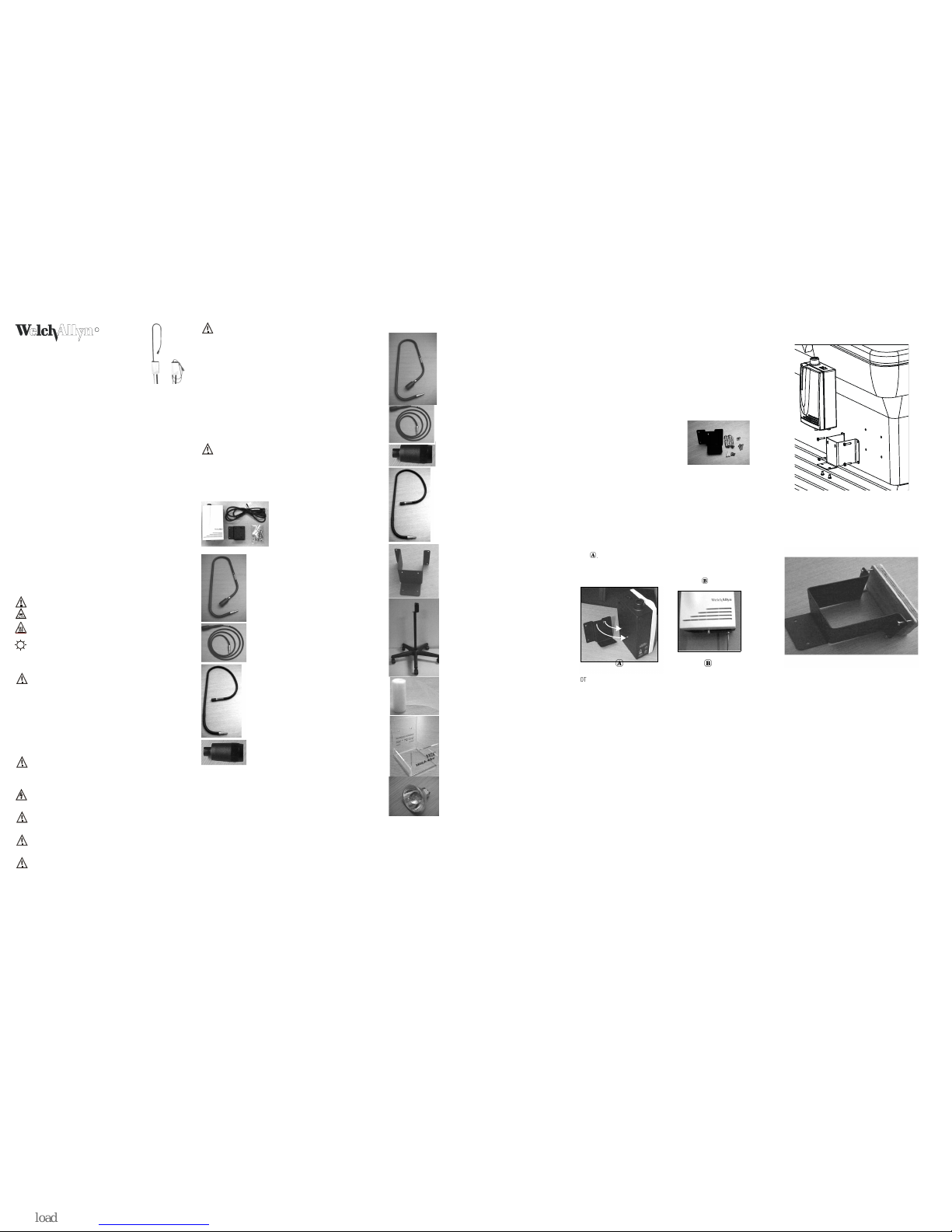
COMPONENTS
Standard
Light Box, Power Cord and Wall Mount
Model 48740 (Domestic)
Model 48742 (Europe)
Model 48744 (UK)
Model 48746 (Australia)
Model 48748 (Japan)
Fiberoptic Light Pipe (shown with focusing sleeve)
Model 48200
(Included only with Model #’s 48700, 48722,
48724, 48726, and 48728)
Fiberoptic Light Cable (shown with focusing sleeve)
Model 48220
(Included only with Model #’s 48780, 48782,
48784, 48786, and 48788)
Neonatal Transilluminator
Model 48210
(Included only with Model #’s 48760, 48762,
48764, 48766, and 48768)
Focusing Sleeve
Model 48605
(Included only with Model #’s 48700, 48722, 48724,
48726, 48728, 48780, 48782, 48784, 48786, and 48788)
Accessories
Fiberoptic Light Pipe (Shown with Focusing Sleeve)
Model 48200
Fiberoptic Light Cable (Shown wi th Focusing Sleeve)
Model 48220
Focusing Sleeve
Model 48605
Neonatal Transilluminator
Model 48210
The optional neonatal Light Pipe/
transilluminator is used to assist in the
diagnosis of pneumothorax, to locate blood
vessels, etc. This transilluminator
incorporates a permanently attached
ultraviolet filter that minimizes the
transmission of ultraviolet light. The standard
Fiberoptic Light Pipe or Fiberoptic Light Cable
should
NOT
be used for transillumination of
neonates.
Table Mount Bracket
Model 48859
Mobile Stand
Model 48850
Disposable Sheaths
Model 52640
Disposable Sheath Dispenser
Model 52641
35W Halogen Replacement Lamp
Model 04200
MOUNTING
Use one of the following three mounting options in order to ensure proper
operation of the light box.
Wall Mount
Choose appropriate mounting location. The length of the light pipe is 4 feet
totally extended (fiberoptic light cable is 7.5 feet). When choosing a mounting
location, keep these dimensions in mind in addition to accounting for the
actual application the light will be used for and what portion of the
examination table will need to be accessed.
1. Using the mounting plate as a template, mark drilling holes a s needed
(depending on your wall type).
2. Dry Wall, Paneling, Plywood or Plaster
(1/8 inch (.3 cm) to 5/8 inch (1.6 cm)
thick) - drill four (4) 3/8 inch (1cm) holes,
insert hollow metal wall anchor
assembly.
3. Concrete Block - drill four (4) 3/16 inch
(.5 cm) holes, insert plastic anchors. Use #8 x 1/2 inch screws to
secure.
4. Metal Panel or Plywood walls greater than 5/8 inch (1.60 cm) thick drill four (4) 1/8 inch (.3 cm) holes. Use #8 x 1 inch screws to secure.
5. Once holes are drilled, install the mounting plate with the appropriate
screws. Completely tighten the screw so there is no gap between the
screw head and the mounting plate.
6. Mount the Light Box to the plate by inserting the pins on the back of the
light box into the slots on the mounting plate. Let the light box drop
down to position the pins into the narrow portion of the mounting slots
.
7. To secure the Light Box to the plate, insert two (2) .50” (1.27cm) screws
through the bottom of the mounting plate and tighten into the bottom
of the Light Box using a phillips head screwdriver
.
NOTE: Some exam table manufacturers supply mounting hardware for
installation of the Exam Lig ht III. Check with your table supplier for
availability.
WARNING: It is the responsibility of the health facility of user to ensure that
the mounting bracket is securely anchored to the wall or table, or that the
mobile stand is securely assembled, and the exam light is securely fastened
to the bracket or stand as directed below. Give consideration to the load that
is placed upon the mount. We lch Allyn, Inc. does not acce pt responsibility for
any installation, nor for damage or injury arising from the installation of any
mounting bracket or mobile stand, regardless of the type of fasteners and
technique used.
1. Determine the side of th e table that is most optimal for mou nting the
light. Consider the locatio n of the nearest power outlet and pati ent
traffic.
NOTE: Verify that the top of the mounting bracket is at least 10 inches (25.4
cm) below the table top cushion and that the mounting position will not
interfere with the operation of the table.
2. Using the mounting plate as a template, mark the hole locations on the
table and drill four (4) .25 inch (.64 cm) holes in the table.
3. Using four 8-32 screws with lock washers and nuts, install the
mounting plate to the table as shown in the diagram.
4. Mount the light box to the plate by inserting the pins on the back of the
light box into the slots on the mounting plate. Let the light box drop
down to position the pins into the narrow portion of the mounting slots.
5. To secure the Light Box to the mounting plate, insert two (2) .50” (1.27
cm) screws through the bottom of the mounting plate and tighten into
the bottom of the Light Box using a Phillips head screwdriver.
NOTE: Some tables require additional reinforcement of the mou nting bracket
to support the mounted light. In this case, we recommend using a 1” (2.5 cm)
thick piece of plywood. When employing this reinforcement to the bracket,
please follow instructions 6 - 11 below.
6. Trace the outline of the mounting pla te and mark the hole locations on
a 3/4 inch (1.9cm) thick piece of plywood.
7. Cut the piece of wood to the outline size and drill four .25 inch (.64cm)
holes.
8. Using the mounting plate as a template, mark the hole locations on the
table and drill (4) .25 inch (.64 cm) holes in the table.
9. Using four 8-32 x 2 inch (5.08 cm) screws with lock washers and nuts,
install the block of wood and mounting plate to the table as shown in
the diagram.
10. Mount the light box to the plate by inserting the pins on the back of the
light box into the slots on the mounting plate. Let the light box drop
down to position the pins into the narrow portion of the mounting slots.
11. To secure the Light Box to the mounting plate, insert two (2) .50”
(1.27cm) screws throug h the bottom of the mounting plate and tighten
into the bottom of the Light Box using a phillips head screwdriver.
Halogen Exam Light III
Mobile Stand
(Model # 48850)
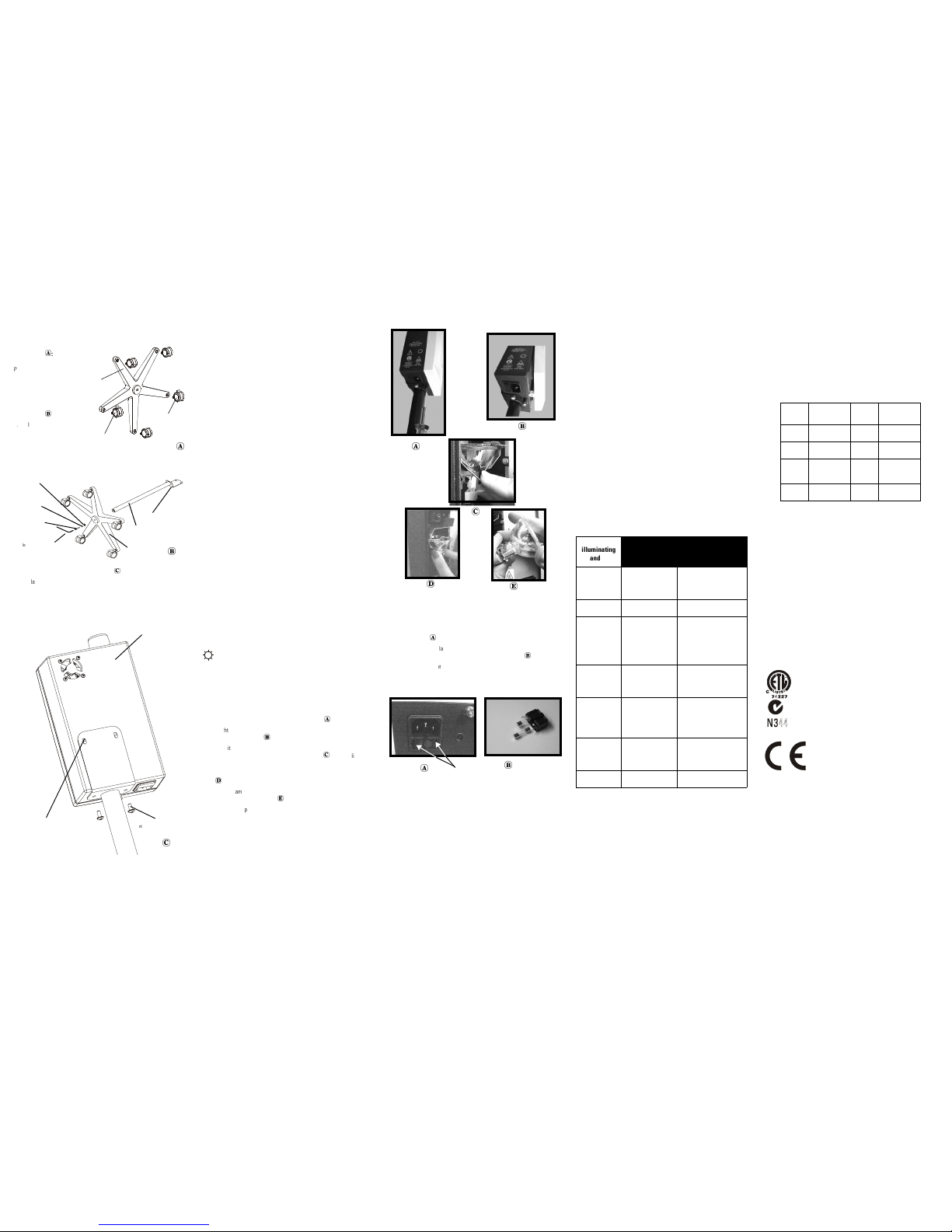
Caster/Base Assembly
Instructions
:
Push casters into the holes of
the base until they “snap ” into
place. Alternate casters as
shown.
Base/Column Assembly
Instructions
:
1. Insert column into
center hole of base.
2. Insert .25 inch (.64 cm)
lock washer, .75 inch
(1.9 cm) flat washer and
1 1/4” (3.2 cm) socket head bolt into center hole. Tighten socket head
bolt with hex socket wrench.
Exam Light/Mounting Plate Instructions
:
1. Place the keyhole pins on the back of the Exam Light into the slots on
the top of the mounting plate and slide down.
2. Line up the screw holes on the bottom of the Exam Light with the screw
holes on the mounting plate.
3. Insert the .50 inch (1.27 cm) screws through the bottom of the mounting
plate and tighten with a phillips head screw driver (not included).
SET-UP AND OPERATION
Set Up
1. Secure the Light Box to one of the mounting options per the appropriate
instructions.
2. Insert the Fiberoptic Light Pipe, Fiberoptic Light Cable, or Neonate Light
Pipe into the light pipe receptacle on the top of the Light Box.
3. Plug the power cord into the base of the Light Box and the remaining
end into a grounded AC outlet.
4. Toggle the light switch to the “ON” position to operate.
NOTE: Remember that the Fiberoptic Light Pipe, Fiberoptic Light Cable, and
Neonate Light Pipe contain several thousand individual optical fibers,
therefore appropriate handling is required to ensure long fiber life. Do not
bend the flexible portions of the light pipe at acute angles as this will break
individual fibers and reduce light transmission. For example, do not bend the
semi-flexible middle por tion of the Fiberoptic Light Pipe mo re than 180
degrees and do not bend the proximal and distal sections more than 90
degrees. Be careful not to pull on the Fiberoptic Light Cable as this may cause
fibers to break.
Operation Of Light Pipe
The flexible portions of th e Fiberoptic Light Pipe are design ed to be
articulated, but not twisted. Twisting or applying torque to the flexible
sections will greatly decrease the life of the Light Pipe. This type of
movement will cause premature drooping of the Light Pipe (will not stay in
place once positioned) and eventually will result in breakage of the fiberoptic
bundle. For best results, always position the Light Pipe by moving it in the
same direction as gravity. For example, if the pipe needs to be raised, raise it
above the desired position and then lower it into place.
NOTE: Upon manufacture, the Light Pipe is tested to assure maintenance of
positioning and to verify the absence of noise upon articulation. Over a period
of time and use, it is normal for the Light Pipe positioning capability to reduce
and soften becoming less ob edient. Abnormal softening or occ urrence of
noise upon articulation should be reported to Welch Allyn Technical Service
(315-685-4560) immediately.
Operation of Focusing Sleeve
The focusing sleeve at the end of the Fiberoptic Light Pipe and Fiberoptic
Light Cable provides adjustment of the illumination spot size. Twisting the
knurled portion of the focusing sleeve in a clockwise direction will make the
spot smaller. Twisting the knurled portion of the focusing sleeve in a
counterclockwise direction will increase the spot size.
LAMP REPLACEMENT
CAUTION: Lamp may be hot. Allow the lamp to cool before replacing.
1. Turn the unit off and unplug the power co rd from both the wall outlet
and the Light Box.
2. Remove the unit from the pati ent area.
3. Using a screwdriver, loosen the single panel fastener that protrudes
from the bottom of the unit. As the screw is loosened, there will be a
noticeable “drop” as the front cover is released.
4. Slightly lift the bottom of the front cover toward you and then slide the
cover up to remove it.
5. For initial lamp replacement only: Grasp wire clip at top of lamp. Rotate
clip toward the base of the unit until it pops out.
Discard clip. It was
for shipping purposes only.
6. Grasp the lamp connector and pull the lamp straight out of its holder.
7. Pull the lamp from its connec tor and replace it with Welch Allyn
Replacement Lamp #04200.
8. Push the lamp back into the holder.
9. Attach the front cover by sliding the tabs at the top of the c over into the
slots at the top of the back housing and then tightening the screw at
the bottom of the unit.
10. Return the unit to the patient area and plug power cord back into
bottom of unit and wall outlet.
FUSE REPLACEMENT
1. Turn the unit off and remove the power co rd from both the wall outlet
and the light box.
2. Press the tabs on both ends of the fuse drawer in and pull the fuse
drawer out.
3. Remove and replace new fuses of the same type. There is no required
orientation of the fuses. Be sure to replace both fuses.
4. Reinsert the fuse holder by pressing it into the power connector until it
snaps into place.
5. If the new fuses blow, immediately c ontact Welch Allyn Technical
Service (315-685-4560).
CLEANING
Focusing Sleeve
For best results, use the disposable sheath model #52640.
1. Remove the focusing sleeve from the Fiberoptic Light Pipe or Fiberoptic
Light Cable by rotating it counterclockwise to unthread.
2. Use a cotton swab soaked in warm water and mild detergent to clean
the distal end of the Fiberoptic Light Pipe or Light Cable, the proximal
side of the Focusing Sleeve (small end), and distal window on the large
end on the Focusing Sleeve.
3. Dry using a new cotton swab.
4. Reassemble the Focusing Sleeve to the Light Pipe or Light Cable by
rotating clockwise.
WARNING: Do not clean any part of the focusing sleeve with alcohol. Clean
only with a mild detergent and water.
NOTE: The focusing sleeve should not be sterilized or immersed.
Fiberoptic Light Pipe, Light Cable, Neonate Light Pipe
For best results, use the disposable sheath model #52640.
External surfaces may be cleaned with a solution of warm water and mild
detergent.
NOTE: The Fiberoptic Lig ht Pipe, Light Cable, and Neonate Li ght Pipe should
not be sterilized or immersed.
Light Box
Note: The Light Box should not be sterilized or immersed.
1. Prior to cleaning, turn power off and disconnect the power cord from
both the wall outlet and the Light Box.
2. The external surfaces may be cleaned by wiping with a cloth dampened
with mild soap and water or by using the following cleaning/
disinfecting solutions. DO NOT IMMERSE.
• 70% Isopropyl Al cohol
• 10% mild bleach solution
• 10% Iodine Based Solution
The power cord may be wiped clean using the same cleaning/disinfecting
solutions listed above. Wipe dry with a clean cloth. Care must be taken not to
get the prongs wet. DO NOT IMMERSE.
TROUBLESHOOTING
MAINTENANCE AND REPAIR
For minor trouble, refer to the troubleshooting section in this manual for
possible causes and corrective action. Only qualified personnel should make
electrical inspections of the Welch Allyn Light Box. To locate qualified
personnel, contact your local authorized Welch Allyn distributor, or call Welch
Allyn directly at 315-685-4560. Tampering with the unit will automatically
void all warranties expressed or implied.
WARRANTY
Light Box - Welch Allyn guarantees that the Light Box is free of any
manufacturing defects or Welch Allyn will repair or replace, free of charge,
any parts proven to be defective through causes other than misuse, neglect,
damage in shipment and no rmal wear and tear. The warranty is for a one year
period from the original date of purchase.
Fiberoptic Light Pipe - The fiberoptic light pipe has been designed to not drift
to a new position once positioned for an exam if the Light Box is mounted
vertically according to the instructions. The warranty is for a one year period
from the original date of purchase provided that the light pipe has not been
tampered with or abused. Any Light Pipe that does not meet these
performance requirements will be repaired or replaced at no charge to the
customer.
SPECIFICATIONS
Electrical
Power Cord
#18AWG, 3 wire grounded cord set, 8 feet (2.5 meters) long.
Physical Characteristics
Weight: 4.75 lb (2.16 Kg), light box only
Light Box H: 8.75 inches (22.23 cm)
Dimensions: W: 5.25 inches (13.34 cm)
D: 3.50 inches (8.89 cm)
Environment
Operating: 60°F (15°C) to 104°F (40°C), 75%
R.H. Max, 500 hPa - 1060 hPa Altitude
Transport/Storage: -4°F (-20°C) to 120°F (49°C ), 95%
R.H. Max, 500 hPa - 1060 hPa Altitude
Equipment Classification
Class I, Continuous Operation
IPXØ: Not protected against the ingress of water.
Approvals
IEC 60601-1, UL 2601-1, CAN/CSA C22.2 No
601.1, AS3200.1, IEC 60601-1-2
EMC Framework of Aus tralia
The CE mark on this product indicates that it has been
tested to and conforms with the pr ovisions noted within
the 93/42/EEC Medical Device Directive.
Authorized European Representative Address:
European Regulatory Manager
Welch Allyn Ltd.,
Kells Road, Navan,
County Meath, Republic of Ireland.
Tel.: 353-46-79060
Fax: 353-46-27128
NOTE: This product complies with current required standards for
electromagnetic interference and should not present problems to other
equipment or be affected by other devices. As a precaution, avoid using this
device in close proximity to other equipment.
NOTE: This product contains no hazardous materials. Its disposal will not
contaminate or harm the environment, or present any risk to individuals
disposing of the product. As a precaution, it is recommended you contact your
local disposal and/or recycling authority for information regarding the
disposal of the equipment.
Locking Caster
Locking
Caster
Base
Hex Socket Wrench
(Allen Wrench)
Socket Head Bolt
.25 inch (.64 cm)
Lock Washer
.75 inch (1.9 cm)
Flat Washer
Base
Column
Mounting Plate
.50 inch (1.27 cm)
mounting screw
Exam Light
Keyhole Pin in slot.
Fuse Tabs
If lamp is not
illuminating
and…
Possible Cause Solution
fan is not oper-
ating.
Light box is not
plugged into either
the wall outlet or the
power cord socket.
Plug the power cord into
the wall outlet and power
cord socket at bottom of
unit.
Power switch is not
turned on.
Depress the green side of
the power switch.
One or both fuses
have blown.
Replace both fuses. Follow
the instructions in the fuse
replacement section. If
fuses continue to blow,
return Light Box to an
authorized repair cent er.
Power cord is dam-
aged. This may cause
intermittent opera-
tion.
Replace the power cord
with a new Welch Allyn
power cord.
No power is sup-
plied to the wall out-
let.
Verify that the wall outlet
has power by checking the
circuit breaker status an d
by operating other equip-
ment at that wall outlet.
fan is operating. The lamp has burned
out.
Replace with a new Welch
Allyn lamp, model # 04200.
Refer to the Lamp Replace-
ment Section.
If light output
seems low.
Lamp is not in opti-
mal orientation.
Rotate lamp 90° in the
lamp holder.
Ref
Model
Input Output Fuse
48740 120VAC∼60Hz,
400mA
12VAC,
3.0A
T500mAL,
250V
48742 230VAC∼50Hz,
250mA
12VAC,
3.0A
T315mAL,
250V
48744 230/
240VAC∼50Hz,
250mA
12VAC,
3.0A
T315mAL,
250V
48748 100VAC∼50/
60Hz, 500mA
12VAC,
3.0A
T630mAL,
250V
US
WELCH ALLYN AUSTRALIA PTY LTD
18-20 ORION ROAD
LAND COVE, NSW 2066
AUSTRALIA
488119E Rev. A
Halogen Exam Light III avec conduit de lumière à fibre
optique
REF - 48700, 48722, 48724, 48726, 48728
Halogen Exam Light III à câble de transmission à fibre
optique
REF - 48780, 48782, 48784, 48786, 48788
Halogen Exam Light III avec conduit de lumière à fibre
optique pour nouveau-nés
REF - 48760, 48762, 48764, 48766, 48768
Boîte à lumière de Halogen Exam Light III avec cordon
d’alimentation
REF - 48740, 48742, 48744, 48746, 48748
Merci d’avoir acheté la lampe d’examen Halogen Exam Light III de Welch
Allyn. Nous pensons qu’il s’agit du produit de la plus haute qualité de cette
sorte qui existe actuellement au monde. Si vous suivez les simples directives
présentées dans ce manuel, ce dispositif vous fournira une performance
fiable et sans problème pendant de nombreuses années. En cas de questions
ou de problèmes, n’hésitez pas à contacter nos services clientèle ou
technique au (800) 535-6663 aux heures normales de bureau.
Welch Allyn poursuit son engagement à fournir des produits diagnostiques
novateurs de qualité aux spécialistes médicaux. Appelez-nous au (800) 5356663 pour recevoir un catalogue de notre ligne de produits ou visitez notre
site Web au www.WelchAllyn.com.
DESCRIPTION DES SYMBOLES
Attention : Consulter le Manuel d’utilisation pour des informations
supplémentaires.
Avertissement : Risque d’incendie. Remplacer les fusibles selon les
indications.
Attention : Températures élevées
Attention : Lumière à haute intensité
DESCRIPTION DES SYMBOLES
AVERTISSEMENT : L’utilisateur de ce matériel doit avoir reçu une
formation approfondie sur les techniques médicales appropriées
quant à l’utilisation de cet instrument. Il convient par ailleurs, de
prendre le temps de lire attentivement les instructions présentées
dans ce manuel avant d’utiliser ce dispositif. Il convient également
de lire attentivement le mode d’emploi des autres appareils utilisés
en conjonction avec l’Exam Light III (par exemple, machines
d’aspiration, générateurs électrochirurgicaux, etc.). Une
compréhension incomplète des exigences de fonctionnement de ce
dispositif peut être à l’origine de lésions de l’utilisateur, du patient
et/ou de détériorations de l’instrument.
ATTENTION : Risque de décharge électrique. Débrancher le cordon
d’alimentation de la prise électrique et laisser l’ampoule se refroidir
avant de la remplacer (ampoule Welch Allyn n
o
04200).
DANGER : Risque d’explosion si ce dispositif est utilisé en présence
d’anesthésiques inflamma bles.
ATTENTION : La réglementation américaine n'autorise la vente de ce
produit que sur prescription médicale.
ATTENTION : L’éclairage est intense. Ne pas regarder la source
lumineuse lorsqu’elle est allumée. Risque d’effet nocif pour les yeux.
ATTENTION : Utiliser la lampe d’examen à la distance de travail
prévue de 30 à 60 cm. Une exp osition à des distances plus
rapprochées peut avoir un effet nocif sur la peau.
AVERTISSEMENT : Ne pas réaliser une transillumination néonatale
sans utiliser le transilluminateur néonatal n
o
48210 (pourvu d’un
filtre UV). Ne pas retirer le manchon de mise au point du conduit de
lumière pour utiliser celui-ci à des fins de transillumination, sous
risque de sévères brûlure s.
Les pratiques générales pour minimiser les risques d’effet nuisible
pour la peau provenant des rayonnements optiques comprennent: la
minimisation de l’intensité de l’éclairage au site d’examen des
tissus, la minimisation des durées d’exposition et la prise de
précautions supplémentaires lorsque la sensibilité de la peau a été
altérée par un traumatisme tissulaire ou l’emploi d’anesthésique.
Les bonnes pratiques générales pour minimiser les risques d’effet
nuisible pour les yeux provenant des rayonnements optiques
comprennent: éviter de regarder directement les puissantes sources
de lumière et leurs réflexions, et protéger les yeux lorsque la taille
des pupilles est normale et que les réactions d’aversion sont
absentes.
Ce dispositif ne contient pas de pièces réparables ou remplaçables
par l’utilisateur autres que l’ampoule et les fusibles. Veuillez confier
toute autre réparation à un centre de réparation habilité et agréé.
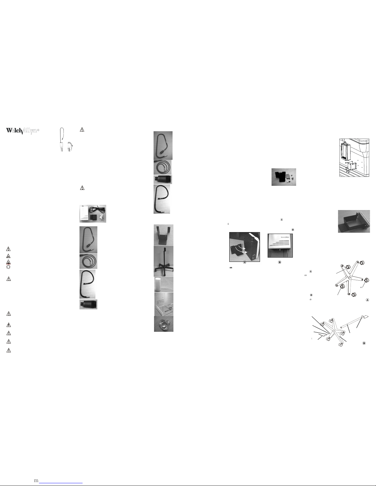
COMPOSANTS
Modèle standard
Boîte à lumière, cordon d’alimentation et
monture murale
Modèle 48740 (États-Unis)
Modèle 48742 (Europe)
Modèle 48744 (Royaume-Uni)
Modèle 48746 (Australie)
Modèle 48748 (Japon)
Conduit de lumière à fibre optique (illustré avec le
manchon de mise au point)
Modèle 48200
(Inclus seulement avec les modèles n° 48700, 48722,
48724, 48726 et 48728)
Câble de transmission à fibre optique (illustré avec le
manchon de mise au point)
Modèle 48220
(Inclus seulement avec les modèles n° 48780, 48782,
48784, 48786 et 48788)
Transilluminateur néonatal
Modèle 48210
(Inclus seulement avec les modèles n° 48760, 48762,
48764, 48766 et 48768)
Manchon de mise au point
Modèle 48605
(Inclus seulement avec les modèles n° 48700, 48722,
48724, 48726, 48728, 48780, 48782, 48784, 48786 et
48788)
Accessoires
Conduit de lumière à fibre optique (illustré avec le
manchon de mise au point)
Modèle 48200
Câble de transmission à fibre optique (illustré avec le
manchon de mise au point)
Modèle 48220
Manchon de mise au point
Modèle 48605
Transilluminateur néonatal
Modèle 48210
Le conduit de lumière/transilluminateur néonatal
optionnel est conçu en tant qu’aide dans le cadre du
diagnostic d’un pneumothorax pour repérer les
vaisseaux sanguins et autres structures. Ce
transilluminateur comprend un filtre ultraviolet
incorporé de façon permanente qui minimise la
transmission des rayons UV. Ceci évite une élévation de
la température cutanée à plus de 4 °C lorsque le
dispositif est en contact avec la peau pendant cinq
minutes ou plus longtemps. Ne pas utiliser le conduit
de lumière standard pour une transillumination chez
des nouveau-nés.
Support pour monture sur table
Modèle 48859
Support mobile
Modèle 48850
Gaines jetables
Modèle 52640
Distributeur de gaines jetables
Modèle 52641
Ampoule halogène 35 W de rechange
Modèle 04200
MONTAGE
Faire appel à l’une des trois options de montage suivantes afin d’assurer le
bon fonctionnement de la boîte à lumière.
Monture murale
Choisir un endroit de montage approprié. Le conduit de lumière mesure 1,20
m lorsqu’il est complètement déployé (le câble de transmission à fibre
optique mesure 2,30 m). Au moment de choisir l’endroit de montage,
conserver ces dimensions à l’esprit outre l’application actuelle pour laquelle
la lampe sera utilisée et la partie de la table d’examen à laquelle on aura
besoin d’avoir accès.
1. En utilisant la plaque de montage comme modèle, marquer les trous à
percer selon les besoins (en fonction du type de mur).
• Cloison sèche, lambris d’appui,
contreplaqué ou plâtre (0,3 cm à 1,6
cm d’épaisseur): percer quatre (4)
trous de 1 cm et insérer des chevilles
métalliques creuses.
• Bloc en béton°: percer quatre (4) trous
de 0,5 cm et insérer des chevilles en
plastique. Fixer en place à l’aide de
vis n° 8 de 1,3 cm.
• Panneau métallique ou murs en contreplaqué de plus de 1,6 cm
d’épaisseur: percer quatre (4) trous de 0,3 cm. Fixer en place à
l’aide de vis n° 8 de 2,5 cm.
2. Une fois les trous percés, installer la plaque de montage à l’aide des
vis appropriées. Serrer l es vis à fond pour éliminer tout espace entre
les têtes de vis et la plaque de montage.
3. Monter la boîte à lumière sur la plaque en insérant les broches situées
au dos de la boîte à lumière dans les fentes de la plaque de montage.
Laisser la boîte à lumière retomber en place afin de positionner les
broches dans la partie étroite des fentes de montage.
4. Pour fixer la boîte à lumière à la plaque, insérer deux (2) vis de 1,27 cm
par la partie inférieure de la plaque de montage et serrer dans la partie
inférieure de la boîte à lumière à l’aide d’un tournevis cruciforme.
.
Monture sur table
(Modèle n° 48859)
REMARQUE : Certains fabricants de tables d’examen fournissent le matériel
nécessaire pour l’installation de la lampe Exam Light III. Vérifier sa
disponibilité auprès du fournisseur de la table.
AVERTISSEMENT : Il incombe à l'établissement médical de l'utilisateur de
s'assurer que le support de montage est bien fixé au mur ou à la table ou que
le support mobile est bien assemblé, et que la lampe d'examen est
correctement fixée sur son support, conformément aux directives ci-dessous.
On doit tenir compte de la ch arge placée sur la monture. Welch Allyn , Inc.
décline responsabilité pour toute installation, ainsi que pour tout dommage
ou blessure provenant de l'installation d'un support de montage ou d'un
support mobile, quel que soit le type de fixation et de technique utilisées.
1. Déterminer le côté de la table où le montage de la lampe sera optimal.
Tenir compte de l’emplacement de la prise de courant la plus proche et
du passage des patients.
REMARQUE : S’assurer que le dessus du support de montage est situé à au
moins 25,4 cm en dessous du coussin recouvrant la table et que la position du
montage ne gêne pas le fonctionnement de la table.
2. En utilisant la plaque de montage comme modèle, marquer les
emplacements des trous sur la table et perforer quatre (4) trous de 0,64
cm dans la table.
3. À l’aide de quatre vis n° 8 de 5,08 cm pourvues de rondelles de blocage
et d’écrous, fixer le bloc de bois et la plaque de montage à la table
ainsi qu’illustré sur le schéma.
4. À l'aide de 4 vis 8-32 munies de rondelles et d'écrous, fixer la plaque
de montage à la table ainsi que l'illustre le schéma. Fixer la boîte à
lumière à la plaque en i nsérant les broches au dos de la boîte à lumière
dans les fentes de la plaque de montage. Laisser la boîte à lumière
s'abaisser afin de positionner les broches dans la partie étroite des
fentes de montage.
5. Pour fixer la boîte à lumière à la
plaque de montage, insérer deux
(2) vis de 1,27 cm par la partie
inférieure de la plaque de
montage et serrer dans la partie
inférieure de la boîte à lumière à
l’aide d’un tournevis cruciforme.
REMARQUE : Certaines tables
nécessitent un renforcement
supplémentaire du support de montage
pour soutenir la lampe montée. Dans
ce cas, il est recommandé d'utiliser un
épais morceau de contreplaqué (2,5
cm). Si l'on recourt au renforcement du
support, suivre les étapes 6 à 11 décrites ci-dessous.
6. Tracer le contour de la plaque de montage et marquer l’emplacement
des trous sur un morceau de contreplaqué de 1,9 cm d’épaisseur.
7. Couper le morceau de bois à la taille du contour et percer quatre (4)
trous de 0,64 cm.
8. En utilisant la plaque de montage comme modèle, marquer les
emplacements des trous sur la table et perforer quatre (4) trous de 0,64
cm dans la table.
9. À l’aide de quatre vis n° 8 de
5,08 cm pourvues de rondel les
de blocage et d’écrous, fixer le
bloc de bois et la plaque de
montage à la table ainsi
qu’illustré sur le schéma.
10. Fixer la boîte à lumi ère à la
plaque en insérant les broches
au dos de la boîte à lumière dans les fentes de la plaque de montage.
Laisser la boîte à lumière s'abaisser afin de positionner les broches
dans la partie étroite des fentes de montage.
11. Pour fixer la boîte à lumière à la plaque de montage, insérer deux (2) vis
de 1,27 cm par la partie inférieure de la plaque de montage et serrer
dans la partie inférieure de la boîte à lumière à l’aide d’un tournevis
cruciforme.
Support mobile
(Modèle n° 48850)
Montage des roulettes et de
la base
:
Enfoncer les roulettes dans les
trous de la base jusqu’à ce
qu’elles s’enclenchent en place.
L’illustration montre des
roulettes de rechange.
Montage de la base et de la
colonne
:
1. Insérer la colonne dans le
trou au centre de la base.
2. Insérer une de 0,64 cm, une rondelle plate de 1,9 cm et un boulon à
tête creuse dans le trou cent ral. Serrer le boulon à tête cr euse avec une
clé six-pans.
Halogen Exam Light III
Roulette à blocage
Roulette à
blocage
Base
Clé six-pans (clé
Allen)
Boulon à tête
creuse
Rondelle plate
Rondelle de
blocage
Base
Colonne
Plaque de montage
 Loading...