


53
Welch Allyn 53, 53000, 5300P, 530T0, 530TP Service Manual
...
Vital Signs Monitor
300 Series
Service Manual
Model 53XXX

Copyright © 2003, Welch Allyn
:
Welch Allyn
registered trademark of Nellcor Puritan Bennett, Inc.
Copyright Notice: Software in this product is copyright© 2003 by Welch Allyn or its vendors. All rights are reserved. The software is
protected by United States of America copyright laws and international treaty provisions applicable worldwide. Under such laws, you are
licensed to use the copy of the software incorporated with this instrument as intended in the operation of the product in which it is
embedded, but the software may not be copied, decompiled, reverse-engineered, disassembled or otherwise reduced to
human-perceivable form. This is not a sale of the software or any copy of the software; all right, title and ownership of the software
remains with Welch Allyn or its vendors. Welch Allyn will make available specifications necessary for inter-operability of this software on
request; however, users should be aware that use of Welch Allyn hardware and software with devices or software not sold by Welch
Allyn or its authorized dealers and affiliates may lead to erroneous results and consequent danger in patient care, and may also void
Welch Allyn's warranty.
®
is a registered trademark of Welch Allyn. Welch Allyn is protected under various patents and patents pending. Nellcor
®
is a
DISCLAIMERS:
Welch Allyn cautions the reader of this manual:
• This manual may be wholly or partially subject to change without notice.
• All rights are reserved. No one is permitted to reproduce or duplicate, in any form, the whole or part of this manual without
permission from Welch Allyn.
• Welch Allyn will not be responsible for any injury to the user or other person(s) that may result from accidents during operation of
the Welch Allyn Vital Signs Monitor.
• Welch Allyn assumes no responsibility for usage not in accordance with this manual that results in illegal or improper use of the
Welch Allyn Vital Signs Monitor.
Welch Allyn Technical Support:
USA 1-800-
Latin America (+1) 305-669-9591
European Call Center (+353) 469-067-790
United Kingdom 0-207-365-6780
535-6663
France (+33) 1-60-09-33-66
Germany (+49) 7477-927-173
Canada 1-800-561-8797
South Africa (+27) 11-777-7509
Australia (+61) 2-9638-3000
Singapore (+65) 6291-0882
Japan (+81) 3-5212-7391
China (+86) 21-6327-9631
For information concerning this document or any
Welch Allyn Monitoring product, contact:
Welch Allyn
Customer Service
8500 SW Creekside Place
Beaverton, Oregon 97008-7107 USA
Within USA, toll free:
Phone Technical Services: (800) 535-6663
WorldWide:
Phone: (503) 530-7500
Fax: (503) 526-4200
Fax Technical Services: (503) 526-4970
Internet: http://www.welchallyn.com
E-mail Technical Services
solutions@monitoring.welchallyn.com
E-mail Marketing Dept.:
marketing@monitoring.welchallyn.com
Welch Allyn European Customer Service
IPA Business Park
Dublin Road
Navan, County Meath, Ireland
Phone: 353-46-67700
Fax: 353-46-27128
Welch Allyn U.K. Ltd.
Cublington Road
Aston Abbotts
Buckinhamshire HP22 4ND, England
Phone: 44-1296-682140
Fax: 44-1296-682104
Welch Allyn Italia
Via Napo Torriani, 29
20124 Milan, Italy
Phone: 39-02-6699-291
Fax: 39-02-6671-3599
Welch Allyn GmbH: Germany
Postfach 31
Zollerstrasse 2-4
72417 Jungingen, Germany
Phone: 49-7477-92-710
Fax: 49-7477-92-7190
Welch Allyn: France
814 Rue Charles de Gaulle
77100 Mareuil les Meaux, France
Phone: 01-6009-3366
Fax: 01-6009-6797
Welch Allyn: Pacific
P.O. Box 39-293 Howick
Auckland, New Zealand
Phone: 64-9-532-9524
Fax: 64-9-532-9526
Welch Allyn: Asia
Room1002, 10/F Tung Sun Comm. Centre
194-200 Lockhart Road, Wanchai, H.K.
Phone: (852) 9016-7812
Fax: (852) 2535-5650
Welch Allyn: Latin America
MD International
11300 NW 41st Street
Miami, FL 33172 USA
Phone: (305) 669-9003
Fax: (305) 669-8951
Reorder Part No: 810-1723-XX
Manual Part No: 810-1651-01 Rev. A 12/03
Printed in USA
0123

Contents
1 - Safety Summary. . . . . . . . . . . . . . . . . . . . . . . . . . . . . . . . . . . . . . . . .5
General Safety Considerations. . . . . . . . . . . . . . . . . . . . . . . . . . . . . . . . . . . . . . . . . . . . . . . .5
Electrostatic Discharge (ESD) . . . . . . . . . . . . . . . . . . . . . . . . . . . . . . . . . . . . . . . . . . . . . . . .6
Symbols . . . . . . . . . . . . . . . . . . . . . . . . . . . . . . . . . . . . . . . . . . . . . . . . . . . . . . . . . . . . . . . .7
2 - Overview. . . . . . . . . . . . . . . . . . . . . . . . . . . . . . . . . . . . . . . . . . . . . .11
Purpose and Scope. . . . . . . . . . . . . . . . . . . . . . . . . . . . . . . . . . . . . . . . . . . . . . . . . . . . . . .11
Technical Support Services . . . . . . . . . . . . . . . . . . . . . . . . . . . . . . . . . . . . . . . . . . . . . . . . .11
Returning Products . . . . . . . . . . . . . . . . . . . . . . . . . . . . . . . . . . . . . . . . . . . . . . . . . . . . . . .12
Product Configurations . . . . . . . . . . . . . . . . . . . . . . . . . . . . . . . . . . . . . . . . . . . . . . . . . . . .13
Recommended Service Intervals . . . . . . . . . . . . . . . . . . . . . . . . . . . . . . . . . . . . . . . . . . . . .13
Service Options. . . . . . . . . . . . . . . . . . . . . . . . . . . . . . . . . . . . . . . . . . . . . . . . . . . . . . . . . .14
Warranty Service. . . . . . . . . . . . . . . . . . . . . . . . . . . . . . . . . . . . . . . . . . . . . . . . . . . . . .14
Non-Warranty Service. . . . . . . . . . . . . . . . . . . . . . . . . . . . . . . . . . . . . . . . . . . . . . . . . .14
Related Documents. . . . . . . . . . . . . . . . . . . . . . . . . . . . . . . . . . . . . . . . . . . . . . . . . . . . . . .14
Service Menu . . . . . . . . . . . . . . . . . . . . . . . . . . . . . . . . . . . . . . . . . . . . . . . . . . . . . . . . . . .15
3 - Functional Verification. . . . . . . . . . . . . . . . . . . . . . . . . . . . . . . . . . .17
Functional Verification Overview . . . . . . . . . . . . . . . . . . . . . . . . . . . . . . . . . . . . . . . . . . . . .17
Equipment Required . . . . . . . . . . . . . . . . . . . . . . . . . . . . . . . . . . . . . . . . . . . . . . . . . . . . . .18
Functional Verification Procedure. . . . . . . . . . . . . . . . . . . . . . . . . . . . . . . . . . . . . . . . . . . . .19
System/Power . . . . . . . . . . . . . . . . . . . . . . . . . . . . . . . . . . . . . . . . . . . . . . . . . . . . . . .19
NIBP . . . . . . . . . . . . . . . . . . . . . . . . . . . . . . . . . . . . . . . . . . . . . . . . . . . . . . . . . . . . . . .22
Inflation . . . . . . . . . . . . . . . . . . . . . . . . . . . . . . . . . . . . . . . . . . . . . . . . . . . . . . . . . . . .25
Pressure Dump. . . . . . . . . . . . . . . . . . . . . . . . . . . . . . . . . . . . . . . . . . . . . . . . . . . . . . .25
Printer. . . . . . . . . . . . . . . . . . . . . . . . . . . . . . . . . . . . . . . . . . . . . . . . . . . . . . . . . . . . . .26
SpO
. . . . . . . . . . . . . . . . . . . . . . . . . . . . . . . . . . . . . . . . . . . . . . . . . . . . . . . . . . . . . .28
2
Temperature . . . . . . . . . . . . . . . . . . . . . . . . . . . . . . . . . . . . . . . . . . . . . . . . . . . . . . . . .30
Nurse Call. . . . . . . . . . . . . . . . . . . . . . . . . . . . . . . . . . . . . . . . . . . . . . . . . . . . . . . . . . .31
Battery . . . . . . . . . . . . . . . . . . . . . . . . . . . . . . . . . . . . . . . . . . . . . . . . . . . . . . . . . . . . .32
Patient Isolation Test. . . . . . . . . . . . . . . . . . . . . . . . . . . . . . . . . . . . . . . . . . . . . . . . . . .32
Checklist and Test Results Report Form. . . . . . . . . . . . . . . . . . . . . . . . . . . . . . . . . . . . . . . .35
Vital Signs Monitor Series 300 3 Service Manual

Contents
4 - Troubleshooting and Repair . . . . . . . . . . . . . . . . . . . . . . . . . . . . . . 37
Troubleshooting Chart. . . . . . . . . . . . . . . . . . . . . . . . . . . . . . . . . . . . . . . . . . . . . . . . . . . . .37
Requirements for Module-level Repair and Replacement. . . . . . . . . . . . . . . . . . . . . . . . . . .39
NIBP Characterization . . . . . . . . . . . . . . . . . . . . . . . . . . . . . . . . . . . . . . . . . . . . . . . . . . . . .39
Welch Allyn Monitor Service Utility . . . . . . . . . . . . . . . . . . . . . . . . . . . . . . . . . . . . . . . . . . .40
Monitor Software Utility Introduction. . . . . . . . . . . . . . . . . . . . . . . . . . . . . . . . . . . . . . .40
Monitor Software Utility Installation. . . . . . . . . . . . . . . . . . . . . . . . . . . . . . . . . . . . . . . .40
Monitor Software Utility Setup. . . . . . . . . . . . . . . . . . . . . . . . . . . . . . . . . . . . . . . . . . . .40
Characterizing NIBP . . . . . . . . . . . . . . . . . . . . . . . . . . . . . . . . . . . . . . . . . . . . . . . . . . .41
5 - Disassembly Procedure. . . . . . . . . . . . . . . . . . . . . . . . . . . . . . . . . . 43
Procedures Overview . . . . . . . . . . . . . . . . . . . . . . . . . . . . . . . . . . . . . . . . . . . . . . . . . . . . .43
Screws. . . . . . . . . . . . . . . . . . . . . . . . . . . . . . . . . . . . . . . . . . . . . . . . . . . . . . . . . . . . .43
Connectors. . . . . . . . . . . . . . . . . . . . . . . . . . . . . . . . . . . . . . . . . . . . . . . . . . . . . . . . . .44
Remove and Disconnect the Battery . . . . . . . . . . . . . . . . . . . . . . . . . . . . . . . . . . . . . . . . . .46
Separate the Front and Rear Chassis. . . . . . . . . . . . . . . . . . . . . . . . . . . . . . . . . . . . . . . . . .47
Disassemble the Front Chassis Assembly . . . . . . . . . . . . . . . . . . . . . . . . . . . . . . . . . . . . . .50
Remove the LCD Display from the Main Board . . . . . . . . . . . . . . . . . . . . . . . . . . . . . . . . . .53
Remove the Main Board from the Rear Chassis Assembly. . . . . . . . . . . . . . . . . . . . . . . . . .53
Disassemble and Remove the NIBP Assembly. . . . . . . . . . . . . . . . . . . . . . . . . . . . . . . . . . .58
Remove and Disassemble the Printer Assembly . . . . . . . . . . . . . . . . . . . . . . . . . . . . . . . . .61
Disassemble the Temperature Module. . . . . . . . . . . . . . . . . . . . . . . . . . . . . . . . . . . . . . . . .68
Disassemble the SpO
Assembly. . . . . . . . . . . . . . . . . . . . . . . . . . . . . . . . . . . . . . . . . . . . .71
2
6 - Replacement Parts . . . . . . . . . . . . . . . . . . . . . . . . . . . . . . . . . . . . . 77
Service Manual 4 Vital Signs Monitor Series 300

1 - Safety Summary
This safety summary, and all additional specific warnings and cautions located throughout
the documentation, must be read and understood by all users of the Vital Signs Monitor
Series 300 monitor.
Caution
End-user software service tools used for previous models of the VSM must
not be used with the VSM Model 300 Series. This includes the “Custom
Repair Software”, part number 130S29E, and any other RS232 utility other
than the Welch Allyn Monitor Service Utility (840-0676-XX). Use of any tool
other than this service utility may set the monitor in an undefined and
unrecoverable state.
United States federal law restricts this device to sale, distribution, or use by or
on the order of a licensed medical practitioner.
General Safety Considerations
Always consider the following safety points when using the monitor:
• Place the monitor and accessories in locations where they cannot harm the patient should
they fall from a shelf or mount.
• Do not connect more than one patient to a monitor.
• Do not connect more than one monitor to a patient.
• Do not use the monitor in an MRI suite or hyperbaric chamber.
• Do not autoclave the monitor.
• Accessories can be autoclaved only if the manufacturer’s instructions clearly approve it.
Many accessories can be severely damaged by autoclaving.
• Inspect the power adapter cord periodically for fraying or other damage. Replace the
adapter as needed. Do not operate the monitor from mains power if the adapter, the
adapter cord, or the cord plug are damaged.
• Frequently check all cables, both electrically and visually.
• To avoid explosion, do not operate the monitor in the presence of flammable anesthetics.
• To ensure patient safety, use only accessories recommended or supplied by Welch Allyn.
(See the Products and Accessories Guide , part number 810-0409-XX.) Always use accessories
according to your facility’s standards and according to the manufacturer’s
recommendations and instructions. Always follow the manufacturer’s directions for use.
Vital Signs Monitor Series 300 5 Service Manual

Electrostatic Discharge (ESD) Safety Summary
• A monitor that has been dropped or otherwise damaged or abused must not be used
until it has been tested and verified by qualified service personnel for proper operation.
• If the monitor detects an unrecoverable problem, an error code and a brief message
appear in the message display. Report all such errors to Welch Allyn.
• While under warranty, the monitor must be serviced only by a Welch Allyn service
technician.
Electrostatic Discharge (ESD)
ATTENTION
CAUTION
SENSITIVE ELECTRONIC DEVICES
DO NOT SHIP OR STORE NEAR STRONG
ELECTROSTATIC, ELECTROMAGNETIC,
MAGNETIC OR RADIOACTIVE FIELDS.
OBSERVE PRECAUTIONS
FOR HANDLING
ELECTROSTATIC
SENSITIVE DEVICES
Warning Electrostatic discharge (ESD) can damage or destroy electronic
components. Handle static-sensitive components only at static-safe
workstation.
Consider all electrical and electronic components of the monitor as staticsensitive.
Electrostatic discharge is a sudden current flowing fr om a charged object to another object or
to ground. Electrostatic charges can accumulate on common items such as foam drinking
cups, cellophane tape, synthetic clothing, untreated foam packaging material, and untreated
plastic bags and work folders, to name only a few.
Electronic components and assemblies, if not properly protected against ESD, can be
permanently damaged or destroyed when near or in contact with electrostatically charged
objects. When you handle components or assemblies that are not in protective bags and you
are not sure whether they are static-sensitive, assume that they are static-sensitive and
handle them accordingly.
• Perform all service procedures in a static-protected environment. Always use techniques
and equipment designed to protect personnel and equipment from electrostatic
discharge.
• Remove static-sensitive components and assemblies from their static-shielding bags only
at static-safe workstations—a properly grounded table and grounded floor mat—and
only when you are wearing a grounded wrist strap (with a resistor of at least 1 megohm
in series) or other grounding device.
Service Manual 6 Vital Signs Monitor Series 300

Safety Summary Symbols
• Use only grounded tools when inserting, adjusting, or removing static-sensitive
components and assemblies.
• Remove or insert static-sensitive components and assemblies only with monitor power
turned off.
• Insert and seal static-sensitive components and assemblies into their original staticshielding bags before removing them from static-protected areas.
• Always test your ground strap, bench mat, conductive work surface, and ground cord
before removing components and assemblies from their protective bags and before
beginning any disassembly or assembly procedures.
Symbols
The symbols illustrated on the following pages appear on the monitor or in this document.
Documentation Symbols
Indicates important information related to the current topic of discussion.
Caution Indicates a condition or practice which, if continued or not corrected
immediately, could cause damage to the equipment.
Warning Indicates a condition or practice which, if continued or not corrected
immediately, could lead to serious illness, injury, or death.
Certification and Operation Labels
This device has been tested and
certified by the Canadian
Standards Association
C
US
International to comply with
applicable U.S. and Canadian
medical safety standards.
Urgent alarm notification (output to
Nurse Call system)
The CE Mark and Notified Body
0123
Vital Signs Monitor Series 300 7 Service Manual
Registration Number signify that
the device meets all essential
requirements of the European
Medical Device Directive 93/42/
EEC.
Recycle used batteries properly
and in accordance with local
regulations.
Do not dispose of batteries in
refuse containers.

Symbols Safety Summary
N344
WELCH ALLYN PTY LTD
5/38-46 SOUTH STREET
RYDALMERE, NSW 2116
AUSTRALIA
Australian Registered Importer Sealed lead-acid battery, 6V 4 Ah
Patient connections are Type BF,
and protected against
defibrillation.
Shipping, Storing, and Environment Labels
Keep this end of the package or
shipping crate up.
Fragile contents—handle with
care.
Do not expose the monitor to
relative humidity above this limit.
Pb
n
Refer to the product
documentation.
Protect the monitor from exposure to
rain.
Do not subject the monitor to
altitudes outside these limits.
Limit stacking to this number of units.
Do not expose the monitor to
temperatures outside these limits.
Monitor Connector Labels
Temperature Probe Cable
SpO
SpO
2
Sensor Cable Connector
2
Connector
RS232 Cable Connector AC Power Adapter Cable Connector
Nurse Call Cable Connector NIBP Hose Connector
Printer Door Label
Press to open the printer door Load paper this direction
Service Manual 8 Vital Signs Monitor Series 300

Safety Summary Symbols
The monitor front panel controls are described in more detail throughout this document.
Front Panel Controls
Set alarm limits Power on/off
Silence alarms Print patient data
Scroll up/down
Scroll forward/back
Increase/decrease value
(The scroll icon appears as these
two arrows in the documentation.)
Set an NIBP automatic
measurement interval
Cycle to the next menu selections
Review patient data
Start/stop an NIBP cycle
(AUTO button)
Vital Signs Monitor Series 300 9 Service Manual

°
°
M
Symbols Safety Summary
Front Panel Displays and Indicators
SYS
DIA
SpO
2
message
window
°
C
°
F
M
Systolic pressure
Diastolic pressure
Arterial hemoglobin oxygen
saturation
Pulse rate pulse
amplitude
indicator
MAP (mean arterial pressure) Neonatal
Degrees Celsius Pediatric
Degrees Fahrenheit Adult
Monitored temperature AC power
Temperature
Pulse strength
Battery charging (flashing)
Battery charged (steady)
Battery low
Battery fully discharged
Service Manual 10 Vital Signs Monitor Series 300

2 - Overview
Purpose and Scope
This service manual is a reference for periodic preventive maintenance and corr ective service
procedures for the Vital Signs Monitor 300 Series.
Corrective service is supported to the level of field-replaceable units. These include some
circuit-board assemblies and some subassemblies, case parts, and other parts. (See
Replacement Parts (page 77) for a complete list of user-replaceable service parts.)
Repair and replacement of the main board is not supported. All service work
on the main board must be performed by certified and qualified service
personnel at an authorized Welch Allyn service center.
Caution No component-level repair of circuit boards and subassemblies is
supported. Use only the repair procedures described in this manual.
Warning When performing a service procedure, follow the instructions
exactly as presented in this manual. Failure to do so could damage the
monitor, invalidate the product warranty, and lead to serious personal injury.
This guide provides troubleshooting information, assembly procedures, and instructions for
functional testing and performance verification. It is intended for use only by technically
qualified service personnel.
This guide applies only to the Vital Signs Model 300 Series. For servicing the pr evious (52000series) version of the Vital Signs Monitor, refer to Welch Allyn service manual 95P445E,
which is available on the TechView CD (900298-1).
Technical Support Services
Welch Allyn offers the following technical support services:
Telephone support
Loaner equipment
Service agreements
Service training
Replacement service parts
Factory Service
For information on any of these services, contact Welch Allyn at the customer-service
numbers listed on page 2 .
Vital Signs Monitor Series 300 11 Service Manual

Returning Products Overview
Returning Products
To return a product for service, contact Welch Allyn Technical Support and request a Return
Material Authorization (RMA) number.
Welch Allyn does not accept returned products without an RMA.
When requesting an RMA, please have the following information available:
• Product name, model number, and serial number
• A complete return shipping address, including a contact name and phone number;
include any special shipping instructions
• A purchase-order number or credit-card number if the product is not covered by
warranty
• A full description of the problem or service request
To ship the unit, please observe these packing guidelines:
• Remove from the package all hoses, connectors, cables, sensors, power cords, and
other ancillary products and equipment, except those items that might be associated
with the problem.
• Use the original shipping carton and packing materials, or as close an approximation
as possible.
• Include a packing list.
• Write the Welch Allyn RMA number with the Welch Allyn address on the outside of
the shipping carton.
United States federal regulations require that any unit received by Factory Service must be
free from blood-borne pathogens before processing. All incoming products are cleaned as
well as possible, but products that cannot be effectively cleaned cannot be accepted for
repair. Please thoroughly clean all organic residues from the product before shipment. This
will ensure safe receipt, processing and repair, and will help expedite the return of your
monitor.
Service Manual 12 Vital Signs Monitor Series 300

Overview Product Configurations
Product Configurations
Model numbers for the configurations are as follows:
Model
Number
53000 NIBP
5300P NIBP, Printer
530T0 NIBP, T emperature
530TP NIBP , Temperature, Printer JA
53N00 NIBP, SpO
53N0P NIBP, SpO
53NT0 NIBP, SpO
53NTP NIBP, SpO
2
, Printer
2
, Temperature
2
, Temperature, Printer
2
Monitoring Parameters Serial
Number
Prefix
Recommended Service Intervals
Interval or Condition Action Recommended Procedure Page
Every 6 - 24 months
(per hospital protocols)
Battery does not hold a
charge
Monitor has been dropped
or otherwise damaged
Monitor malfunctioning Complete functional test
Monitor does not pass
Functional V erification
Complete functional test
Check battery capacity
Replace battery
Complete functional test
Troubleshooting and repair
followed by functional test
Functional Verification 17
Functional Verification
Disassembly Procedure
Functional Verification 17
Functional Verification 17
Troubleshooting and Repair
Disassembly Procedure
Functional Verification
17
43
37
43
17
Vital Signs Monitor Series 300 13 Service Manual
Return to authorized service
center

Service Options Overview
Service Options
Warranty Service
All repairs on products under warranty must be performed or approved by Welch Allyn.
Refer all warranty service to Welch Allyn Factory Service or another authorized Welch Allyn
Service Center. Obtain an RMA number for all returns to Welch Allyn Factory Service – see
Returning Products (page 12) .
Caution Unauthorized repairs will void the product warranty.
Non-Warranty Service
Welch Allyn Factory Service and authorized Service Centers support non-warranty repairs.
Contact any Welch Allyn regional service center for pricing and service options.
Welch Allyn offers modular repair parts for sale to support non-warranty service. This
service must be performed only by qualified end-user biomedical/clinical engineers using
this service manual.
The Welch Allyn Monitor Service Utility supports certain service functions. For information,
see page 40 .
Related Documents
Title Part Number Reorder Number
Vital Signs Monitor 300 Series Directions for Use (English) 810-1632-XX 810-1726-XX
Vital Signs Monitor 300 Series Directions for Use (French) 810-1716-XX 810-1727-XX
Vital Signs Monitor 300 Series Directions for Use (Spanish) 810-1715-XX 810-1729-XX
Vital Signs Monitor 300 Series Directions for Use (German) 810-1713-XX 810-1728-XX
Vital Signs Monitor 300 Series Directions for Use (Italian) 810-1712-XX 810-1725-XX
Welch Allyn Parts and Accessories Guide 810-0409-XX 810-0409-XX
Service Manual 14 Vital Signs Monitor Series 300

Overview Service Menu
Service Menu
To see the service menu, first power the monitor off. Press and hold for 3 seconds. While
is depressed, press . The monitor displays the message Service Mode, runs a self-test,
and then displays the main software version number (M: 1.00.00). Press repeatedly to
cycle to the menu selection of interest.
SYS
SpO2 %
DIA
/min
RESET TO DEF A ULT
YES
NO
BP CYCLES:XXXXXX
RUN TIME:XXXXX
3 seconds
SERVICE MODE
Power-up Self-test
Main SW version
M: X.XX.XX
NIBP SW version
N:XX.XX.XX
BATTERY :X.XX V
NIBP TEST
Vital Signs Monitor Series 300 15 Service Manual
POWER OFF
Exit Service Mode
SpO2 SW version
S:X.X.X.X
Temperature SW version
T:X.X

Service Menu Overview
Service Manual 16 Vital Signs Monitor Series 300

3 - Functional Verification
Functional Verification Overview
This section describes the procedure for a complete functional test to support recommended
preventive-maintenance schedules.
The verification includes tests for a monitor configured with the printer, temperature, and
SpO
options. Perform only the tests applicable to the actual configuration.
2
A checklist of the functional tests is provided on page 35. It is recommended that you print a
copy of the checklist each time you perform the functional verification procedure, so that you
can record and save the test results. If the monitor ever requires service, the records of test
results can often facilitate troubleshooting.
Functional verification does not require opening the monitor case.
Vital Signs Monitor Series 300 17 Service Manual

Equipment Required Functional Verification
Equipment Required
The following equipment is required for functional verification of a fully configured monitor.
Commercially Available General-purpose/Medical Test Equipment
Item Manufacturer Part Number/Specification
Power supply Variable, 0-8 VDC, 0.75A (minimum), with
voltage and current indicators (for 1mA current
measurement)
Digital pressure meter Netech Digimano 1000 or equivalent
AC withstand voltage (hi-pot) tester Associated Research 3605 or equivalent
SpO2 functional tester
(for testing the monitor only)
SpO2 extension cable (required for SRC-MAX) Nellcor DEC-8
SpO2 simulator
(for testing the monitor and the SpO2 sensor)
Syringe, 60 mL, Slip tip, Luer BD (Becton, Dickinson) 309654 or equivalent
Hi-pot cable connectors See page 34.
Timer
Nellcor SRC-MAX
Fluke (Biotek) Index2 XL/XLFE or equivalent
Welch Allyn Accessories and Test Equipment
Temperature test key
(for testing the monitor only)
9600 Temperature calibration tester
(for testing the monitor and the temperature probe)
Neonatal cuff hose, 96” 008-0265-XX
Neonatal #1 cuff, disposable, box of 10 008-0620-XX
500 cc air volume T112854
DC power adapter 5200-101A
Battery substitution connector
(Use the female end from the cable set)
Welch Allyn Monitor Service Utility
(required for NIBP repair or replacement;
not required for functional testing)
Service Serial Cable (for use with the Welch Allyn
Monitor Service Utility 840-0676-XX)
NIBP tubing connector, threaded 600-0021-XX
tubing, 1’ 600-0179-XX
Tee, plastic 600-0043-XX
06138-000
01800-210, 110V
01800-500, 220V
01800-810, 220V UK
01800-910, 220V Australia
660-0237-XX
840-0676-XX
008-0842-XX
Service Manual 18 Vital Signs Monitor Series 300

Functional Verification Functional Verification Procedure
Functional Verification Procedure
System/Power
Setup
• If the monitor is configured with the temperature option, connect the temperature probe
and insert it into the probe well.
• If you are using the optional Welch Allyn Model 9600 Calibration Tester (01800-200), plug
it in and set it to 96.4° F (35.8° C).
• If the monitor is configured with the SpO
option, connect the SpO2 sensor.
2
Battery Charge and Beeper
1. Disconnect the power adapter from the monitor.
2. Verify that the charge LED is off.
3. Connect the power adapter. The monitor emits a single beep tone.
4. Verify that the charge LED is on.
Depending on the charge level of the battery, the charge LED may be either
flashing or steady.
flashing indicates that the monitor is running on AC, the battery is
charging, and the battery is charged to less than 90% capacity.
steady indicates that the monitor is running on AC, the battery may or
may not be charging, and the battery is charged to at least 90% capacity.
Battery Substitution Cable Setup
1. Disconnect the power adapter.
2. Remove the battery cover and remove and disconnect the battery.
3. Separate the connector pair (660-0237-00). Use the end that is identical to the connector
on the battery as a battery substitution test cable.
4. Connect the open-ended red (+) and black (-) wires of this cable to the variable DC power
supply.
5. Set the power supply to 6.0 V ± 50 mV.
6. Connect the test power cable to the battery connector on the monitor.
Vital Signs Monitor Series 300 19 Service Manual

Functional Verification Procedure Functional Verification
Monitor-Off Current
With the monitor powered down, verify that the current draw from the power supply is
less than 1 mA.
Power-On Self-Test
1. Power the monitor on.
If the monitor displays error E38, power the monitor off and then power it on
again.
2. Verify that the start-up tone (double beep) is audible.
3. Verify that all front-panel lights (background indicators, LCD pixels, and LED segments
and periods) come on in the proper order: left, center, and right.
Initialization/Idle Mode Current
If your monitor is configured without the temperature option and without the
option, skip these steps and proceed to Baseline Current Draw.
SpO
2
1. If the temperature option is present:
a. Verify that the temperature probe is in the probe well.
b. Set the temperature mode to MONITOR.
c. Remove the temperature probe from the probe well.
d. Verify that the temperature reading appears within 4 seconds.
e. Do not return the probe to the probe well.
2. If the SpO
a. Verify that the SpO
option is present:
2
sensor cable is connected to the monitor.
2
b. Verify that the current draw from the bench power supply is less than 800 mA.
3. Disconnect the SpO
sensor (if equipped).
2
4. Insert the temperature probe (if the monitor is so equipped) into the probe well.
Service Manual 20 Vital Signs Monitor Series 300

Functional Verification Functional Verification Procedure
Baseline Current Draw
1. With the monitor powered on, wait for the monitor LEDs to blank. In this state, the
SpO2 % reads - -, the time of day is displayed in the message window, and the rest of the
displays are blank.
2. Note and record the exact current from the power supply. (This value will be used in the
NIBP and printer tests.)
Battery Voltage
1. Power the monitor off.
2. Simultaneously press and hold and to bring up the monitor in SERVICE MODE.
(When the monitor completes the power-on self-test in service mode, the main software
version number appears in the message display.)
3. Press repeatedly until BATTERY VOLTAGE appears in the message display.
4. Verify that the displayed battery voltage is within 0.1 volt of the DC power supply input.
5. Exit Service Mode by turning off the monitor and then turning it on again.
Vital Signs Monitor Series 300 21 Service Manual

Functional Verification Procedure Functional Verification
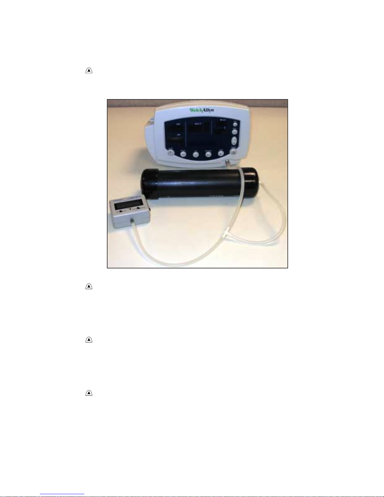
NIBP
Characterization Test
1. Attach a neonate hose (part 008-0265-01) to the NIBP fitting on the monitor.
2. Prepare the 60-mL syringe as follows, with reference to the illustration below:
a. Move the syringe plunger to the 35 mL line.
b. Drill a small hole (for example, 9/64”) through the syringe and the plunger shaft, at a
location between the plunger and the top of the syringe.
c. Insert a rod or bolt (for example, a 6-32 screw) through the hole so that the plunger
cannot move, creating a constant volume in the syringe of 35 mL ± 2 mL. Secure the
rod or bolt so that it cannot fall out of the hole.
-- 60
--
-- 50
--
-- 40
--
-- 30
--
-- 20
--
-- 10
--
ml
3. Insert the tip of the syringe into the open end of the neonate hose, and verify that the fit is
tight and secure.
4. Set the monitor patient type to Adult, as follows:
a. Press once.
b. If the monitor is not already in Adult mode, press once or twice until Adult
appears in the message display.
c. Press .
5. Press .
6. Verify that the error code C03 appears in the message display within a few seconds.
Service Manual 22 Vital Signs Monitor Series 300

Functional Verification Functional Verification Procedure
Warning If the error code C03 does not appear, characterize NIBP according
to the instructions presented on page 41, and then repeat the NIBP
characterization test.
Do not use the monitor if it does not pass the NIBP characterization test. If the
NIBP module is not properly characterized, the monitor could overinflate a
neonatal cuff, which could create a hazard for neonatal patients.
If you cannot characterize the NIBP module, remove the monitor from service
immediately and return it to Welch Allyn for service. (See Returning Products
on page 12.)
7. Put the monitor in Service mode as follows:
a. Power the monitor off.
b. Power the monitor on while pressing .
Verification
1. Attach a #1 neonatal cuff and hose to the monitor. Wrap the cuff securely around a solid
cylindrical object of circumference between 1.6 and 1.9 inches (4.1 and 4.8 cm).
2. Press repeatedly until NIBP TEST appears on the LCD and 0 is displayed on the SYS
and DIA LEDs.
When you first enter the NIBP test mode, give the monitor about a minute to
initialize NIBP before you change the target test pressure.
When switching from one target pressure to the next, give the monitor time to
fully inflate and stop before you select the next target pressure.
In the NIBP test mode, press repeatedly to select the target NIBP test
pressure. The target pressure is displayed on the DIA LEDs. The measured
instantaneous pressure determined by the monitor is displayed on the SYS
LEDs.
3. Press once to select 80 mmHg (10.7 kPa). The cuff inflates to approximately 1 15 mmHg
(15.3 kPa).
In the NIBP test mode, and especially at small test volumes, the pressure
achieved can vary significantly (30-40 mmHg or 4-5.3 kPa) from the target
pressure.
4. Wait 15 seconds, and note the current pressure.
Vital Signs Monitor Series 300 23 Service Manual
Functional Verification Procedure Functional Verification
5. Wait another 10 seconds, note the current pressure, and verify that it has not dropped
more than 8 mmHg (1.1 kPa) below the pressure noted in step 4.
6. Press several times to select 0 mmHg (0 kPa). The valve opens to release pressure.
7. Disconnect the neonate cuff and replace it with the 500 cc volume test setup.
8. Press once to select 80 mmHg (10.7 kPa). The cuff quickly inflates to approximately 80
mmHg (10.7 kPa), and then settles at a slightly lower pressure level. Wait a few seconds
for the pressure to stabilize.
9. Verify that the value displayed in SYS is within 3 mmHg (0.4 kPa) of the value displayed
on the digital pressure meter.
10. Press to select 150 mmHg (20 kPa) target pressure. The cuff quickly inflates to
approximately 150 mmHg (20 kPa), and then settles at a slightly lower pressure level.
Wait a few seconds for the pressure to stabilize.
11. Verify that the value displayed in SYS is within 3 mmHg (0.4 kPa) of the value on the
digital pressure meter.
12. Press to select 300 mmHg (40 kPa). The cuff quickly inflates to approximately 300
mmHg (40 kPa), and then settles at a slightly lower pressure level. Wait a few seconds for
the pressure to stabilize.
13. Verify that the value displayed in SYS is within 6 mmHg (0.8 kPa) of the value on the
digital pressure meter.
Service Manual 24 Vital Signs Monitor Series 300
 Loading...