


 Loading...
Manuals
Service Manual
Operator’s Manual
NOTICE
The information in this document is subject to change without notice.
Welch Allyn makes no warranty of any kind on this material, including but not limited to, the implied warranties of merchantability and fitness for a particular purpose. Welch Allyn shall not be liable for errors contained herein or for incidental or consequential damages concerning the furnishing, performance, or use of this material.
This document contains proprietary information that is protected by copyright. All rights are reserved. No part of this document may be photocopied, reproduced or translated to another language without prior written consent of Welch Allyn.
Before using this instrument, read this guide and become thoroughly familiar with the contents.
Welch Allyn only considers itself responsible for any effects on safety, reliability and performance of the equipment if:
1assembly operations, extensions, re-adjustments, modifications or repairs are done by persons authorized by Welch Allyn, and
2the electrical installation of the relevant room complies with the IEC or national requirements, and
3the instrument is used according to the instructions for use presented in this manual.
WARNING
Welch Allyn assumes no liability for failures resulting from RF interference between Welch Allyn medical electronics and any radio frequency device at levels exceeding those established by applicable standards.
The use of accessories other than those recommended by Welch Allyn may compromise product performance.
United States Federal law restricts this device to sale by or on the order of a licensed health care practitioner.
ii
Table Of Contents
1 |
HOW THIS MANUAL WORKS ..................................................................................................................... |
1 |
|
|
1.1 |
A QUICK TOUR OF THE WELCH ALLYN ATLAS MONITOR ............................................................................... |
2 |
2 |
MONITORING THE PATIENT...................................................................................................................... |
4 |
|
|
2.1 |
MONITORING BLOOD PRESSURE...................................................................................................................... |
6 |
|
2.1.1 MAP (Mean Arterial Pressure) ............................................................................................................. |
8 |
|
|
2.2 |
MONITORING SPO2, PULSE RATE AND THE SPO2 WAVEFORM....................................................................... |
10 |
|
2.3 |
MONITORING HEART RATE AND THE ECG WAVEFORM................................................................................ |
13 |
|
2.4 |
MONITORING IMPEDANCE RESPIRATION (MODELS 622XX & 623XX) ........................................................... |
16 |
|
2.5 |
MONITORING TEMPERATURE (MODELS 622XX & 623XX)............................................................................. |
18 |
|
2.6 |
MONITORING CO2, RESPIRATION RATE, AND THE ETCO2 WAVEFORM (MODEL 623XX) ............................. |
20 |
3 |
MANAGING THE ALARMS ........................................................................................................................ |
22 |
|
|
3.1 |
PATIENT ALARMS.......................................................................................................................................... |
26 |
|
3.1.1 Factory Default Patient Alarm Settings .............................................................................................. |
27 |
|
|
3.2 |
MEASUREMENT INVALID ALARMS ................................................................................................................ |
28 |
|
3.3 |
INSTRUMENT PROBLEM ALARMS................................................................................................................... |
29 |
|
3.4 |
BATTERY ALARMS (MODELS 622XX & 623XX) ............................................................................................ |
30 |
4 |
CAPTURING AND DISPLAYING TREND DATA .................................................................................... |
32 |
|
5 |
USING PRINT AND WAVEFORM FREEZE ............................................................................................. |
34 |
|
|
5.1 |
THE PRINTER – LOADING PAPER AND TROUBLESHOOTING ........................................................................... |
36 |
6 |
CONNECTING TO THE PATIENT............................................................................................................. |
38 |
|
|
6.1 |
CONNECTING THE NIBP CUFF....................................................................................................................... |
40 |
|
6.2 |
CONNECTING THE SPO2 FINGERCLIP SENSOR ................................................................................................ |
43 |
|
6.3 |
CONNECTING THE ECG ELECTRODES ........................................................................................................... |
45 |
|
6.4 |
CONNECTING THE TEMPERATURE PROBE (MODELS 622XX & 623XX) .......................................................... |
49 |
|
6.5 |
CONNECTING THE END TIDAL CO2 SAMPLE TUBE (MODEL 623XX).............................................................. |
50 |
7 |
USING THE MENUS...................................................................................................................................... |
51 |
|
|
7.1 |
THE SET DATE AND TIME AND OTHER OPTIONS MENU................................................................................. |
51 |
|
7.2 |
THE ADVANCED CONFIGURATION MENU ...................................................................................................... |
53 |
|
7.2.1 Advanced Configuration Menu Settings.............................................................................................. |
55 |
|
8 |
CLEANING AND MAINTAINING THE ATLAS MONITOR.................................................................. |
57 |
|
9 |
UNPACKING AND INSTALLING THE ATLAS MONITOR .................................................................. |
59 |
|
10 APPENDIX A: TECHNICAL SPECIFICATIONS FOR THE ATLAS MONITOR................................ |
61 |
||
11 APPENDIX B: ELECTROMAGNETIC COMPATIBILITY (EMC)........................................................ |
69 |
||
12 APPENDIX C: CALIBRATION AND MAINTENANCE........................................................................... |
73 |
||
13 APPENDIX D: ACCESSORIES FOR THE WELCH ALLYN ATLAS MONITOR ............................... |
74 |
||
14 |
APPENDIX E: TROUBLESHOOTING ....................................................................................................... |
77 |
|
15 |
INDEX .............................................................................................................................................................. |
91 |
|
iii
Safety Information
The Welch Allyn Atlas Monitor is intended for use in a hospital or clinical environment. It should not be used at home or in emergency transport vehicles. Monitor users should be skilled at the level of a technician, nurse, doctor or medical specialist.
The function of the Welch Allyn Atlas Monitor is to register ECG, CO2 concentration, Heart Rate, Noninvasive Blood Pressure (Systolic, Diastolic, and Mean Arterial Pressure), Pulse Oximetry, Respiration Rate and Temperature for adult and pediatric patients (over the age of 3 years), in all hospital or clinic facilities.
To ensure patient electrical isolation, the Atlas Monitor should only be connected to other equipment that provides patient electrical isolation. When connecting the Welch Allyn Atlas Monitor to any instrument, verify proper operation before clinical use. Accessory equipment connected to the monitor’s serial data interface must be certified according to IEC Standard 950 for data-processing equipment or IEC Standard 601-1 for electromedical equipment. All combinations of equipment must be in compliance with IEC Standard 601-2 systems requirements. Anyone who connects additional equipment to the signal input / output port is configuring a medical system and is therefore responsible that the system comply with the requirements of IEC Standard 601. If in doubt, consult the Welch Allyn Technical Service Department.
The Welch Allyn Atlas Monitor and its accessories should be tested by qualified service personnel at regular intervals to verify proper operation, according to the procedures of the user’s institution. A Service Manual is available from the manufacturer. Other important safety information is located throughout this manual where appropriate.
iv

Warnings, Cautions, and Notes
All operating personnel should be familiarized with the general safety information in this summary. Specific warnings and cautions will also be found throughout the operator’s manual. Such specific warnings and cautions may not appear here in this summary.
|
|
Conforms to IEC 60601-1 |
|
|
UL 2601-1 |
|
|
CAN/CSA C22.2 No 601-1 |
C |
US |
Approved to Australia AS 3200.1, Appendix Z |
|
|
Defibrillator-proof, Type CF Applied Part |
Attention, consult accompanying document
Handle with care
Storage temperature. Refer to technical specification for more details.
Lead Acid Battery. For disposal see the Maintenance section of this manual.
Storage humidity. Refer to technical specification for more details.
Warning – Tells you about something that could hurt the patient or hurt the operator. Caution – Tells you about something that could damage the monitor.
Note – Tells you other important information. v
Warnings
•The Welch Allyn Atlas Monitor is designed for use by medical clinicians. Although this manual may illustrate medical monitoring techniques, this system should only be used by a trained clinician who knows how to take and interpret a patient’s vital signs.
•Do not operate this product in the presence of flammable anesthetics. Explosion may result.
•WARNING – PACEMAKER PATIENTS. Rate meters may continue to count the pacemaker rate during occurrences of cardiac arrest or some arrhythmias. Do not rely entirely upon rate meter alarms. Keep pacemaker patients under close surveillance. See this manual for disclosure of the pacemaker pulse rejection capability of this instrument.
•This device must be used in conjunction with clinical signs and symptoms. This device is only intended to be an adjunct in patient assessment. Certain arrhythmias or pacemaker signals could adversely affect heart rate indications or alarms.
•During defibrillation, keep the discharge paddles away from ECG and other electrodes, as well as other conductive components in contact with the patient. Avoid contact with any accessories connected to the Welch Allyn Atlas Monitor’s panel.
•Prolonged use or the patient’s condition may require changing the SpO2 sensor site periodically. Change sensor site and check skin integrity, circulatory status, and correct alignment at least every 4 hours.
•When monitoring blood pressure over an extended period of time, or at frequent intervals, it is recommended to check the cuff site and cuffed extremity regularly for possible ischemia, purpura and/or neuropathy.
•Thoracic impedance respiration measurement may interfere with some pacemakers. Refer to the pacemaker’s manual.
•To ensure patient safety, the conductive parts of the ECG electrodes (including associated connectors) and other patient-applied parts, should not contact other conductive parts, including earth ground, at any time.
•The safety and effectiveness of this product in the detection of apnea, particularly for infants and neonates, has not been established.
•This equipment must not be connected to any other equipment that is not compliant with EN60601-1, or a possibility exists that combined leakage currents could exceed safe limits.
•WARNING: Use of accessories, transducers, and cables other than those specified may result in degraded electromagnetic compatibility performance of this device.
•Do not operate this product with MRI (Magnetic Resonance Imaging) equipment.
•It is the operator’s responsibility to set alarm limits as appropriate for each individual patient.
•Any Atlas Monitor which has been dropped or damaged should be checked by qualified service personnel to insure proper operation prior to use.
•There are no user serviceable parts inside the Atlas Monitor other than paper replacement and battery replacement.
•Blood pressure measurements may not be accurate for patients experiencing moderate to severe arrhythmias.
•This Atlas Monitor should not be used on patients who are linked to heart / lung machines.
•If the integrity of the external protective conductor in the installation or its arrangements is in doubt, equipment shall be operated from its internal power source (models 622xx and 623xx).
•If an electrosurgical unit is used, place the ECG cable and wires as far as possible from the site of the surgery and from the electrosurgical cables. This will minimize interference and the risk of burns to the patient. Ensure that the electrosurgical return cable (neutral) is well attached and making good contact with the patient.
vi
•End tidal carbon dioxide (ETCO2) and breath rate measurement and alarm capability are active ONLY when the second trace option is set to CO2. Should the operator change from viewing the ETCO2 and breath rate waveforms and data to another second trace selection (SpO2, Respiration or ECG) the CO2 and breath rate monitoring and alarm capability will be disabled. This occurs even if the watertrap and cannula are still inserted into the Monitor.
•Impedance Respiration rate measurement and alarm capability are active ONLY when the second trace option is set to Respiration. Should the operator change from viewing the Respiration
waveforms and breath rate to another selection (SpO2, CO2 or ECG) the Respiration rate monitoring and alarm capability will be disabled. This occurs even if the ECG cable is still inserted into the Monitor.
Cautions
•Place the Welch Allyn Atlas Monitor and accessories in locations where they cannot harm the patient if they fall off a shelf or mount.
•Never place fluids on top of this monitor. In case of fluid spilling on the monitor, disconnect power cord, wipe clean immediately and have the monitor serviced to ensure that no hazard exists.
•This Welch Allyn Atlas Monitor should not be stacked directly on top of other equipment, and other equipment should not be stacked on top of this Welch Allyn Atlas Monitor. If stacking is necessary, observe the Welch Allyn Atlas Monitor to verify normal operation in the stacked configuration in which it will be used.
•Unplug the external power cord from the monitor before cleaning or disinfecting the monitor.
•Do not autoclave, subject to ethylene oxide sterilization, or immerse the Welch Allyn Atlas Monitor in liquid. Sterilize accessories only according to the manufacturer’s instructions.
•Make frequent electrical and visual checks on cables and electrode wires.
•Ensure the AC rating for the device is correct for the AC voltage at your installation site before using the monitor. The AC rating is shown on the back of the instrument. If the rating is not correct, do not use the monitor, and contact the Welch Allyn Technical Service Department for help.
•Line isolation monitor transients may resemble actual cardiac waveforms and thus inhibit heart rate alarms. Use care in placement of ECG electrodes and routing of cables to avoid interference and noise.
•Electrode polarization: the type of electrode used can affect the recovery time from overload, especially defibrillation. Electrodes of dissimilar metals should not be used.
•If the accuracy of any measurement is in question, check the patient’s vital sign(s) by an alternate method and then check the Atlas Monitor for proper functioning.
•Extremity and cuff motion should be minimized during blood pressure determinations.
•The pulse oximeter is calibrated to determine the percentage of arterial oxygen saturation of functional hemoglobin. Significant levels of dysfunctional hemoglobins such as carboxyhemoglobin or methemoglobin may affect the accuracy of the measurement.
•Grounding reliability can only be achieved when equipment is connected to an equivalent receptacle marked “Hospital Only” or “Hospital Grade”.
Notes
•Sidestream waste material and the CO2 watertrap should be treated as biohazard material.
•Blood pressure measurements determined with this device are equivalent to those obtained by a trained observer using the cuff/stethoscope auscultation method, within the limits prescribed by the
vii
American National Standard, Electronic or automated sphygmomanometers (SP 10).
•Blood Pressure measurements can be affected by the position of the patient, by the patient’s physiological condition, and other factors.
•The Blood Pressure system and Temperature system may not meet specifications if operated or stored at conditions outside the stated ranges, or subjected to excessive shock or dropping.
•The Blood Pressure system is compliant with requirements of EN 1060-3:1995 Specification for Noninvasive sphygmomanometers.
•The Atlas Monitor is designed with protective circuitry and current isolation that eliminates any risk to the patient from possible software errors.
Product Warranty Information
Welch Allyn warrants the Welch Allyn Atlas Monitor, when new, to be free of defects in material and workmanship and to perform in accordance with manufacturer’s specifications for a period of two years from the date of purchase from Welch Allyn or its authorized distributors or agents. (Pulse oximetry sensors and temperature probes are warranteed for one year). Welch Allyn will either repair or replace any components found to be defective or at variance from the manufacturer’s specifications within this time at no cost to the customer. It shall be the purchaser’s responsibility to return the instrument to Welch Allyn or an authorized distributor, agent, or service representative. This warranty does not include breakage or failure due to tampering, misuse, neglect, accidents, modification or shipping. This warranty is also void if the instrument is not used in accordance with manufacturer’s recommendations or if repaired by other than Welch Allyn or an authorized agent. Purchase date determines warranty requirements. No other express warranty is given.
Return the Instrument Registration Card
Remember to submit the instrument registration card for warranty validation. Complete the information and mail the pre-addressed card to Welch Allyn. You may also register on-line at <http://www/welchallyn.com/medical/support/warranty>.
Service Information: Service Policy
All service and repairs must be performed by authorized Welch Allyn personnel or agents, using approved Welch Allyn replacement parts and approved process materials. Failure to do so will invalidate the product warranty. Please refer to the product warranty for specific coverage.
Service Information: Technical Assistance
If you have an equipment problem that you cannot resolve, call the Welch Allyn Service Center nearest you for assistance. Technical service support is available to you by telephone on normal business days at the phone numbers listed below.
viii
If you are advised to return a product to Welch Allyn for service or repair, schedule the repair with the service center nearest you.
Before returning a product for repair you must obtain authorization from Welch Allyn. An RMA (Return Materials Authorization) number will be given to you by our service personnel. Be sure to note this number on the outside of your shipping box. Returns without an RMA number will not be accepted.
ix
Service Information
For Technical Support or to obtain return instructions, please contact your nearest Welch Allyn service center listed below:
Welch Allyn, Inc. |
Welch Allyn, GmbH - Germany |
4341 State Street Road |
Zollerstrasse 2-4 |
Skaneateles Falls, NY 13153-0220 |
D72417 Jungingen, Germany |
Phone: 1-800-535-6663 |
Phone: 011-49-7477-9271-73 |
Fax: 315-685-4653 |
Fax: 011-49-7477-9271-93 |
Welch Allyn, Ltd. - Canada |
Welch Allyn, Ltd. - Singapore |
160 Matheson Blvd. E., Unit #3 |
6001 Beach Road #21-09 |
Mississauga, Canada L4Z 1V4 |
Golden Mile Tower |
Phone: 905-890-0004 |
Singapore 199589 |
Fax: 905-890-0008 |
Phone: 011-65-291-0882 |
Welch Allyn, Ltd. - UK |
Fax: 011-65-291-5780 |
|
|
Aston Abbots, Buckinghamshire |
Welch Allyn, Ltd. - Australia |
England HP22 4ND |
PO Box 864 |
Phone: 011-44-1296-689905 |
Ground Floor, 18-20 Orion Road |
Fax: 011-44-1296-682104 |
Lane Cove, NSW 2066, Australia |
|
Phone: 011-61-294-183-155 |
|
Fax: 011-61-294-183-650 |
CLINICAL SUPPORT
For clinical questions about Atlas Monitor call the Welch Allyn Clinical Support line at 800-769-4014 Extension 3225 or 315-685-4100 Extension 3225.
x
The CE Mark on this product indicates it has been tested to and conforms with the provisions noted with the 93/42/EEC Medical Device Directive.
European contact for regulatory compliance:
European Regulator Manager
Welch Allyn LTD.
Navan, Co, Meath
Republic of Ireland
Phone 353-46-79060
Fax: 353-46-27128
Service Information: Service Manual / Spare Parts
A service manual is available by request to qualified electronics personnel. The service manual is a comprehensive guide to troubleshooting, service and repair of the Welch Allyn Atlas Monitor.
A complete spare parts price list is available upon request. Spare parts may be ordered from your local Welch Allyn Service Center.
Service Information: Service Loaners
Service loaners are provided, on request, when repair service is provided by a Welch Allyn Service Center. Loaners for products repaired while under the original warranty, or while under extended warranty or service contract, are provided free of charge and are shipped within 48 hours of notification of need. Shipment charges to the user are paid by Welch Allyn.
For service repairs outside of warranty or contract, loaners will be available for a nominal charge and will be shipped subject to availability. Loaners will be shipped pre-paid.
xi
1 How This Manual Works
This manual is arranged so that everything about one topic is found in a single section. The statement immediately below the chapter title (like this one) appears in italics and presents the important points of the topic. Most topics include an illustration or a table. The chapters are numbered so that logically connected topics begin with the same number-- for example 2.1 and 2.2.
The Welch Allyn Atlas Monitor and this manual are designed for ease of use. Everything you need to know about a specific operation of the monitor is available in one place. This means you can see all the required information at a glance.
Redundancy - There is some redundancy in this manual; some step-by-step procedures are repeated in many places wherever they are pertinent. We did this so you would not have to search through other pages to find what you need to know “right now.”
For instance, setting an alarm limit is fully explained in the section on blood pressure, again in the section on SpO2, and in several other places.
Paragraphs - The statement in italics immediately below the chapter heading describes what the section is about. Sometimes just reading this and looking at the illustrations
will give you enough information.
Section Numbers - The double numbered pages indicate the relationship between the main subject and closely related topics.
The sections are organized so that what you want to know first is put first. Like most medical professionals who use the Atlas Monitor, you are probably very adept at taking blood pressure and connecting ECG leads to patients, so the section on how the Atlas Monitor is used for monitoring patients and what you need to know to operate the monitor comes first. We put the information on connecting blood pressure cuffs and ECG leads in a later section.
This manual is not meant for reading straight through, like a book, although you can read it that way. If you read it like this, the built-in redundancy may become a little tedious. When your read a paragraph or a step-by-step procedure with which you are already familiar, just skip it. It is there for the person who is doing the activity for the first time.
1
1.1 A Quick Tour of the Welch Allyn Atlas Monitor
When you turn on the power, the monitor starts with preset or default alarm levels. Waveforms are displayed on the screen. Readings are displayed on the screen and on LEDs. You can perform the most common operations — set and silence alarms, display trend data, print waveforms and trend data — from the front panel without using a menu. This section gives only a brief overview of the monitor; later sections present all the details.
Which model do you have? The Welch Allyn Atlas Monitor is a single, portable unit providing all the measurement capability normally needed to monitor patients under anesthesia, patients recovering from surgery, and patients who require bedside monitoring. The model number is encoded into the first three digits of the serial number on the back of the unit. There are three models:
Model |
Features |
621SO |
SpO2, SpO2 waveform |
621SP |
Pulse Rate |
|
NIBP: Systolic, Diastolic, MAP |
|
ECG waveform, heart rate |
|
Printer (optional) |
622SO |
All features of model 621xx, |
622SP |
plus: |
622NO |
Impedance Respiration |
622NP |
Patient Temperature |
|
Battery Operation |
|
PC Communication |
|
Remote Nurse Call |
|
Printer (optional) |
623SP |
All features of model 622xx, |
623NP |
plus: |
|
End Tidal CO2 and Breath Rate |
|
from ETCO2 |
|
Printer (standard) |
Power on - The Power On/Standby button is in the lower right corner. When you first turn on the monitor:
•all alarms are enabled, but no alarm will sound until after a valid measurement value is received.
•all alarm limits are set at their default values.
•all the trend data (history) is cleared.
A lit AC~ indicator, located below the screen, means the unit is being powered by the wall outlet, and that the battery is being charged (models 622xx and 623xx).
Silencing Alarms - You can silence any alarm for 90 seconds by pressing the large blue Silence button on the right-hand edge of the instrument. Silenced alarms continue to flash, as long as the measurement is outside the alarm limits.
You can suspend an individual alarm by pressing its ALARM Off button. There are four ALARM Off buttons, each controlling a different group of measurements. The audible alarm is suspended as long as the red LED in the button is lit. When an alarm is suspended, the audible alarm will not sound, but readings will still flash when the measurement is outside the limits.
Trend Data - Trend data is captured every time blood pressure is measured, whether this event is automatic or manual. Trend data is also automatically captured every 15 minutes if blood pressure intervals are longer, or blood pressure is not used. Push the Trend button to see the trend data. Scroll through the trend data with either Set button. Push Trend again to return to the waveform display. The monitor will hold up to 144 lines of trend data, which is 36 hours if data is captured every 15 minutes.
Printing - A printer option is available with both models 621xx and 622xx, and is a standard model 623xx feature. Push the Print button to print what is on the screen. If the waveforms are displayed on the screen, the Print button prints 15 seconds
2
of waveforms plus all the current measurements. The printout captures data from 9 seconds before the Print button was pressed until 6 seconds after. If trend data is displayed on the screen, Print prints all the trend data.
If your model of the Atlas Monitor does not have the optional printer, the Print button is labeled Freeze, and it freezes, or halts, the waveform display for 10 seconds to permit studying of the waveform.
3
2 Monitoring the Patient
The patient’s vital measurements are displayed as numeric readings and as waveforms. You can set the measurement limit alarm levels, silence the alarms for a short period, and suspend individual alarms. You can print waveforms and current measurements, or print all the stored trend data.
The front panel has two sides:
The left side displays |
The right side has |
waveforms, numeric |
measurements |
readings, and trend |
displayed in green |
data on a CRT screen. |
and red LEDs. |
Each side responds to the adjacent Select and Set buttons used for setting alarm limits. Each side also has ALARM Off buttons, which are used to suspend (turn off) individual alarms.
Note: The temperature measurement does not have an alarm.
Setting alarm limits - Press the Select button to choose which alarm limit you want to set. Each time you press the Select button, it cycles to the next alarm, shown by small HI and LO indicators, and the measurement display flashes the current alarm setting. The Set button changes this alarm limit. Press the top or bottom of the button to change the limit up or down.
Note: the flashing alarm setting mode only lasts 10 seconds before reverting back to the normal measurement mode. If you take too long to set a limit, you’ll need to press the Select button and start over again.
Press the Select button to go to the next measurement alarm. Press it several times to cycle out of all the alarm settings and go back to the normal measurement mode.
Silencing alarms - The Silence button silences all alarms for 60, 90 or 120 seconds. This silence
period can be set to one of these three choices in Advanced Configuration. During the silence period, there will be no audible alarms, even for measurements that go outside the limit range for the first time. However, any measurement that is outside the limits you set will flash.
Trend data - Press the Trend button to see the trend data. The waveform display is replaced by the first screen of trend data, starting with the most recent measurements at the top. View the rest of the trend data by pressing the Set button up or down.
The trend memory can hold up to 144 lines of measurements, which is 36 hours of data if taken at 15 minute intervals.
Printing - The Print button prints what you see on the screen - the waveforms (including all current measurements) or the screen with trend data. When you push the button, waveforms are printed starting from 9 seconds before you pushed the Print button until 6 seconds after you pushed the button for a total printout of 15 seconds. The other information on the printout is captured at the time that the Print button is pressed.
Freeze – If your monitor does not have a printer, the button is labeled Freeze. Pressing Freeze stops the waveform display for 10 seconds, and then the readout resumes.
4

Top – Model 623xx showing waveform display and alarm controls
Bottom – Model 623xx showing trend display and associated controls
5
2.1 Monitoring Blood Pressure
Blood pressure can be measured at timed intervals which you set, or you can start the blood pressure measuring cycle manually. Systolic and Diastolic readings are shown on the LEDs at the upper right of the monitor. You can set the high and low alarm limits for both the systolic and diastolic measurements.
Blood pressure cycles - You can measure NIBP at timed intervals or manually. To set a timed interval, press the Auto button to cycle through the available intervals: X, 1, 3, 5, 10, 15, 30, or 60 minutes. Wait until the number for the selected interval stops flashing; the measurement will automatically begin 20 seconds later.
Note: The interval is timed from the start of one BP cycle to the start of the next cycle.
Pressing the button one more time after the 60 is lit will return the Auto timing to the Off mode (indicated by an “X”). In this mode, automatic measurement at timed intervals will not occur. Initially, both blood pressure displays will be blank.
Stopping a blood pressure cycle - The BP Start/Cancel button does one of two things:
•If a blood pressure measurement is not in progress, pressing BP Start/Cancel will start a blood pressure measurement cycle, whether the Auto timer is set to a specific interval or is off.
•If a blood pressure measurement is in progress, pressing BP Start/Cancel will deflate the cuff immediately and cancel the measurement. If the Auto button is in one of the timed modes, the cuff will inflate again after the selected number of minutes.
Note: Canceling a blood pressure cycle does not end automatic BP timing. If the Auto is set to any number, the next blood pressure cycle will start again after that number of minutes have elapsed.
Alarms - When any of the blood pressure limits are exceeded, an audible alarm sounds and the affected measurement flashes. You can silence this alarm, and all alarms, by pressing the large blue Silence button at the right side of the instrument. This will silence all alarms for 60, 90, or 120 seconds, depending on the setting selected in Advanced Configuration. However, any measurement still outside the set limits will flash.
To suspend the blood pressure alarms, press the BP ALARMS Off button so the red LED in the button lights. A suspended alarm will still flash if it goes outside the range of the limits, but it will not sound the audible alarm.
Trend data – Trend data is captured at each blood pressure cycle, whether it is started automatically or manually. If the Auto timing of NIBP is off (X), or greater than 15, then trend data is captured every 15 minutes.
Initial pressure – The initial cuff pressure can be set in the Advanced Configuration. The Atlas Monitor will pump up to the selected initial cuff pressure. If this pressure is too low to measure the systolic pulse, the system will repeatedly increase pressure by 40 mmHg and measure again.
6

Atlas Monitor showing NIBP displays, controls and tubing connector
Setting alarm limits - To set the Systolic and Diastolic alarm limits, use the Select and Set buttons on the right side of the monitor to follow these steps:
•Press the Select button to cycle through
SpO2 LO, then Systolic HI and LO, and Diastolic HI and LO.
•Each push of Select moves you to the next limit. Stop at the limit you want to set. The measurement and the HI or LO LED will flash, indicating which limit is being changed.
•Press the Set button up or down to raise or lower the alarm limit. (When you come to the end of the range, the numbers will stop changing).
•Press the Select button again to go to the next limit, or press it several times until none of the measurements flash and no HI or LO LEDs are lit. The instrument is now in
7
its normal measurement mode. (If you do not press any button for 10 seconds, the instrument will automatically revert to its normal measurement mode).
2.1.1 MAP (Mean Arterial Pressure)
Mean Arterial Pressure is calculated from the systolic and diastolic measurements. MAP may be optionally displayed by selecting it on the Advanced Configuration menu. MAP is displayed in the upper left corner of the screen.
MAP - (Mean Arterial Pressure) display can be turned on and off by using the Advanced Configuration menu. When MAP is shown, you will see it in the upper left corner of the screen, above the ECG waveform.
To display (or turn off) MAP, enter the Advanced Configuration menu:
•Press the Date/Time button.
•Press the Trend button.
•Use the left Select button to highlight “MAP.”
•Press the left Set to choose “Yes” or “No.”
•Press the Trend button again to exit Advanced Configuration.
If MAP is displayed on the screen, it will also appear in the trend data and in the current readings of a waveform printout.
Alarms - When either of the MAP limits are exceeded, an audible alarm sounds and the affected measurement flashes. You can silence this alarm, and all alarms, by pressing the large blue Silence button at the right side of the instrument. This will silence all alarms for 60, 90, or 120 seconds, depending on the setting selected in Advanced Configuration. However, any measurement still outside the set limits will flash.
To suspend the MAP alarm, press the BP ALARMS Off button so the red LED in the button lights. A suspended alarm will still flash if it goes outside the range of the limits, but it will not sound the audible alarm.
Note: MAP is calculated mathematically from the Systolic and Diastolic pressures; it is not
measured directly.
Setting alarm limits – If MAP is displayed, you can set the alarm limits, using the Select and Set buttons on the left side of the monitor to follow these steps:
•Press the left Select button to cycle through MAP HI and LO, Heart Rate HI and LO, Respiration HI and LO (models 622xx
or 623xx) , then (model 623xx) CO2 HI and
LO.
•Each push of Select moves you to the next limit. Stop at the limit you want to set. The measurement and HI or LO will flash, indicating which limit is being changed.
•Press the Set button up or down to raise or lower the alarm limit. (When you come to the end of the range, the numbers will stop changing).
•Press the Select button again to go to the next limit, or press it several times until none of the measurements flash and no HI or LO indicators are lit. The instrument is now in its normal measurement mode. (If you do not press any button for 10 seconds, the instrument will automatically revert to its normal measurement mode).
8

Atlas Monitor waveform display showing location of MAP reading
9
2.2 Monitoring SpO2, Pulse Rate and the SpO2 Waveform
The oximetry and pulse rate measurements are generally taken with the reusable fingerclip sensor (provided), however a wide variety of SpO2 sensors are available as accessory items. The oximetry pulse volume is displayed as a vertical bar graph, called the Plethysmograph, beside the SpO2 % display on the right side of the monitor. The SpO2 pulse tone gives an audible indication of pulse rate and oxygen level.
Pulse - A fingerclip sensor provides the source of the light transmitted through the patient’s finger to determine the oximetry and pulse rate measurements. The green Pulse Rate numbers may sometimes differ slightly from the Heart Rate displayed over the ECG waveform, even though they both measure beats per minute (bpm). This is normal.
Oxygen level - The oxygen level is displayed in red numbers as a percentage. The Plethysmograph vertical bar graph next to the SpO2 percentage shows the strength of the fingerclip sensor signal with each beat. If this signal is low, it could indicate that the fingerclip sensor is not placed properly, or that the patient has poor perfusion. Pigmented skin and nail polish can also lower the signal.
System Displays – The system will begin displaying the Plethysmograph signal almost immediately upon attachment of the fingerclip sensor to the patient. The SpO2 level and Pulse Rate will be displayed within about 5 seconds, after the system determines that the reading is stabilized.
Second waveform - The pulse oximetry waveform can be selected as a second trace. If this is chosen, the bottom line of the screen displays the SpO2 waveform. Select the Second trace source from the Advanced Configuration menu.
Pulse tone - A short SpO2 tone sounds with every pulse beat.
•The pulse tone timing is based on the ECG heart rate. If ECG is not used, the pulse tone timing is based on the SpO2 measurement.
•The pulse tone pitch is determined by the oxygen level, increasing in frequency (pitch) as the percentage of oxygen elevates.
The pulse tone volume can be controlled by a button on the lower right panel. The button is below the SpO2 display, labeled with a speaker icon and SpO2.
Note: The pulse tone volume can be turned completely off with this button.
Note: If the SpO2 is inactive, the timing of the SpO2 pulse tone is in synchrony with the ECG heart rate as is normally the case, but the pitch of the tone is steady, unvarying, and different from the tone tracking oxygen content.
Alarms - When the oxygen percentage falls below the SpO2 limit, an alarm sounds and the affected measurement flashes. You can silence this alarm, and all alarms, by pressing the large blue Silence button at the right side of the instrument. This will silence all alarms for 60, 90, or 120 seconds, depending on the setting selected in Advanced Configuration. However, any measurement still outside the set limits will flash.
To suspend the SpO2 alarm, press the SpO2 ALARMS Off button so the red LED in the button lights. A suspended alarm will still flash if it goes outside the range of the limits, but it will not sound the audible alarm.
10

Atlas Monitor showing SpO2 displays, controls, and sensor connector
Setting alarm limits - To set the SpO2 alarm limits, use the Select and Set buttons on the right side of the monitor to follow these steps:
•Press the Select button to cycle through
SpO2 LO, then Systolic HI and LO, and Diastolic HI and LO.
•Each push of Select moves you to the next limit. Stop at the limit you want to set. The measurement and the HI or LO LED will flash, indicating which limit is being changed.
•Press the Set button up or down to raise or lower the alarm limit. (When you come to the end of the range, the numbers will stop changing).
•Press the Select button again to go to the next limit, or press it several times until none of the measurements flash and no HI or LO LEDs are lit. The instrument is now in its
normal measurement mode. (If you do not press any button for 10 seconds, the instrument will automatically revert to its normal measurement mode).
Pulse and Heart Rate alarms - There is one case where the Heart Rate alarm receives status information from the Oximeter pulse rate:
If ECG is inactive and the Heart Rate is shown as dashes, the Heart Rate alarm is triggered by the Pulse rate instead of the ECG Heart Rate.
If the Pulse rate falls outside the Heart Rate limits, the Pulse measurement flashes and the alarm sounds. Use the large blue Silence button to temporarily silence the alarm, and use the SpO2 ALARMS Off button to suspend it.
11
Saving volume settings – You can save your volume settings for alarms and for pulse tone after you change them, so that they become the initial settings every time the Atlas Monitor is powered on. After making the alarm and pulse volume changes, press Date/Time to display the Other Options menu, and press Print (or Freeze) to save your settings. Press Date/Time to return to the main screen. You may repeat this whenever you want to change your settings.
12
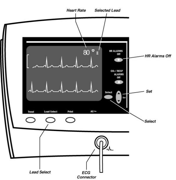
2.3 Monitoring Heart Rate and the ECG Waveform
The trace displays one of the ECG leads. This lead is indicated above the right end of the trace, near the ♥ symbol and heart rate value. Choose the lead with the Lead Select button. Heart rate is displayed at the right.
ECG displays – The ECG waveform is always displayed on the upper half of the screen. The ECG waveform cascades (continues) from the upper half of the screen to also appear at the bottom portion when other waveforms are not selected in Advanced Configuration. The Heart Rate is displayed above the right end of the top waveform, near the ♥ symbol. The symbol for the selected ECG lead is shown to the right of the Heart Rate.
There is always a scale reference bar shown to the left of the upper ECG waveform. This scale bar has a height that represents a 1 mV signal.
The apparent height of the scale bar will vary depending upon the ECG gain setting being used, but will always correspond to a 1mV signal.
Selecting leads - Press Lead Select to change the lead display. The ECG function can use either 3 wire leads - I, II, III , or 5 wire leads -
I, II, III, aVR, aVL, aVF, and V. 3 wire or 5 wire lead setting is selected in the Advanced Configuration menu.
Note: When using 3 wire leads, the ECG lead set must be set correctly. Incorrect results and noisy waveforms can be obtained if the system is configured for 5 wire leads when using 3 wire leads.
Alarms - When either of the Heart Rate limits are exceeded, an audible alarm sounds and the affected measurement flashes. You can silence this alarm, and all alarms, by pressing the large blue Silence button at the right side of the instrument. This will silence all alarms for 60,
90, or 120 seconds, depending on the setting selected in Advanced Configuration. However, any measurement still outside the set limits will flash.
To suspend the Heart Rate alarms, press the HR ALARMS Off button so the red LED in the button lights. A suspended alarm will still flash if it goes outside the range of the limits, but it will not sound the audible alarm.
If ECG is inactive for any reason, the Heart Rate display will be dashes “---” and the Heart Rate alarm will respond to the pulse oximetry rate.
Setting alarm limits –To set the Heart Rate alarm limits, use the Select and Set buttons on the left side of the monitor to follow these steps:
•Press the left Select button to cycle through MAP HI and LO, Heart Rate HI and LO, Respiration HI and LO (models 622xx or
623xx) , then (model 623xx) CO2 HI and
LO.
•Each push of Select moves you to the next limit. Stop at the limit you want to set. The measurement and HI or LO will flash, indicating which limit is being changed.
•Press the Set button up or down to raise or lower the alarm limit. (When you come to the end of the range, the numbers will stop changing).
•Press the Select button again to go to the next limit, or press it several times until none of the measurements flash and no HI or LO indicators are lit. The instrument is now in its normal measurement mode. (If you do not press any button for 10 seconds, the instrument will automatically revert to its normal measurement mode).
13
Atlas Monitor showing ECG waveform display, controls, and ECG connector
14

ECG settings in Advanced Configuration - The five settings in the Advanced Configuration menu associated with the ECG are listed in this table:
Note: When using 3 wire leads, the ECG lead set must be set correctly. Incorrect results and noisy waveforms can be obtained if the system is configured for 5 wire leads when using 3 wire leads.
Advanced Configuration
|
|
ECG setting |
Possible values |
ECG gain |
automatic | |
|
10 mm/mV |
ECG lead set |
3 wire | 5 wire |
|
|
ECG speed |
6.25 | 12.5 | 25 mm/s |
|
|
ECG bandwidth |
Monitor | Extended |
|
|
Second trace |
ECG | SpO2 | |
selection |
Respiration | CO2 |
You can change the ECG settings in Advanced Configuration:
•Press the Date/Time button.
•Press Trend.
•Use either Select button to highlight ECG gain, ECG lead set , ECG speed, ECG bandwidth, or Second trace selection.
•Use the Set button to change any of these values.
•Press Trend to exit Advanced Configuration
ECG gain - The height of the vertical ruler that appears to the left of the ECG waveform indicates a 1 mV amplitude and is 10 mm high if 10 mm/mV gain is chosen. When automatic gain is selected the ruler height will vary, but it will always indicate a 1 mV signal size. The ruler size is automatically increased or decreased to scale to a particular set of waves, but the vertical line still indicates the same amplitude of 1 mV.
ECG lead set - The Atlas Monitor allows for both 3 wire and 5 wire ECG lead sets.
ECG speed - The amount of ECG waveform shown on the CRT is determined by the trace speed. A slower trace speed means more seconds of waveform are shown on the CRT.
ECG bandwidth - The ECG waveform can be displayed and printed in either Monitor or Extended bandwidth. Monitor mode allows for a clearer picture of the waveform by filtering out noise. Extended mode, usually used with cardiac paced patients, shows the finer nuances of ECG waveform, facilitating the detection of conditions such as ischemia.
Note: Detection of ischemia is the interpretation of the clinician only, the Atlas Monitor does not provide automated ischemia detection.
Note: It is normal for the ECG baseline to wander slightly in Extended bandwidth.
Pacemaker signals – The Atlas Monitor displays pacemaker signals exactly as they are captured. There is no option to display symbolic pace indications. Use Extended bandwidth for enhanced display of pacemaker signals.
15
2.4 Monitoring Impedance Respiration (Models 622xx & 623xx)
The lower trace can display the Impedance Respiration waveform if this is chosen in Advanced Configuration. In this case, the Respiration Rate is displayed above the right side of the waveform. The Impedance Respiration waveform is always derived from Lead I (RA-LA).
What is it? - Respiration Rate is measured with the ECG leads. As the chest expands and contracts during the respiration cycle, the resistance, or impedance, between the RA-LA electrodes (Lead I) changes. The result of these changes indicates the respiration rate.
For best performance in monitoring impedance respiration rate, change the LA and RA electrode placement to the mid-axillary line on each side of the chest as shown in the section on connecting the ECG.
Where is it? - In Atlas Monitor model 622xx, the lower trace normally shows cascading ECG. In Atlas Monitor model 623xx, the lower trace normally displays the ETCO2 waveform. However, the lower trace can instead show Impedance Respiration, if it is chosen in Advanced Configuration.
How to display it – You can change the Second trace selection settings in Advanced Configuration:
•Press the Date/Time button.
•Press Trend.
•Use either Select button to highlight Second trace selection.
•Use either Set button to choose Respiration
from the choices ECG, SpO2, Respiration, CO2 (model 623xx).
•Press Trend to exit Advanced Configuration.
Impedance Respiration is sensitive to patient
movement, making it less accurate than ETCO2 for measuring the breath rate. For this reason, model 623xx users often prefer to view the ETCO2 waveform and let the monitor measure breath rate from this source.
Alarms - When either of the respiration rate limits are exceeded, an audible alarm sounds and the affected measurement flashes. You can silence this alarm, and all alarms, by pressing the large blue Silence button at the right side of the instrument. This will silence all alarms for 60, 90, or 120 seconds, depending on the setting selected in Advanced Configuration. However, any measurement still outside the set limits will flash.
To suspend the respiration rate alarms, press the
CO2/RESP ALARMS Off (RESP ALARMS Off) button so the red LED in the button lights. A suspended alarm will still flash if it goes outside the range of the limits, but it will not sound the audible alarm.
Warning: Impedance Respiration rate measurement and alarm capability are active ONLY when the second trace option is set to Respiration. Should the operator change from viewing the Respiration waveforms and breath rate to another selection (SpO2, CO2 or ECG) the Respiration rate monitoring and alarm capability will be disabled. This occurs even if the ECG cable is still inserted into the Monitor.
16

Atlas Monitor showing Impedance Respiration waveform display, controls, and ECG connector
Setting alarm limits –To set the Respiration |
the end of the range, the numbers will stop |
alarm limits, use the Select and Set buttons on |
changing). |
the left side of the monitor to follow these steps: |
• Press the Select button again to go to the |
• Press the left Select button to cycle through |
next limit, or press it several times until |
MAP HI and LO, Heart Rate HI and LO, |
none of the measurements flash and no HI or |
Respiration HI and LO, then (model 623xx |
LO indicators are lit. The instrument is now |
only) CO2 HI and LO. |
in its normal measurement mode. (If you do |
• Each push of Select moves you to the next |
not press any button for 10 seconds, the |
limit. Stop at the limit you want to set. The |
instrument will automatically revert to its |
measurement and HI or LO will flash, |
normal measurement mode). |
indicating which limit is being changed. |
|
• Press the Set button up or down to raise or |
|
lower the alarm limit. (When you come to |
17 |
|
2.5 Monitoring Temperature (Models 622xx & 623xx)
The Temperature, measured on the skin surface with a skin sensor, is displayed in °F or °C, as chosen in Advanced Configuration. There are no audible alarms for Temperature. An invalid temperature reading is indicated by dashes “---” in the numeric display.
Temperature can be measured with a skin sensor.
No alarms – There are no temperature alarm limits and no audible alarms for temperature. If there is no temperature probe connected when the monitor is first turned on, the TEMP display will be blank.
If the probe becomes disconnected from the patient or the monitor, the TEMP display will show steady dashes “---”, but there will be no alarm.
Changing the scale – The temperature display can be in ° F or ° C, as selected in Advanced Configuration.
You can change the Temperature units setting in
Advanced Configuration:
•Press the Date/Time button.
•Press Trend.
•Use either Select button to highlight
Temperature units.
• Use either Set button to choose ° F or ° C.
•Press Trend to exit Advanced Configuration.
Note: The temperature display is blank at poweron until a temperature probe has been detected.
18

Atlas Monitor showing Temperature display and connector
19
Loading...