


WSC060-120
Table of contents
 Loading...
Packaged Heat Pumps
Precedent
WSC060-120
50 Hz
™
February 2004
PKGP-PRC004-EN
Introduction
Precedent™…The same Trane
quality…with added flexibility.
Precedent is a flexible line of packaged
units that cover a wide variety of
applications.
ReliaTel™ microprocessor controls
provide superior flexibility for the
simplest to the most sophisticated
applications. In addition to controls,
Precedent offers many other outstanding
features and option choices.
© 2003 American Standard Inc. All rights reserved. PKGP-PRC004-EN
With its sleek compact cabinet, rounded
corners and beveled top, it may just be
the most aesthetically pleasing packaged
unit on the planet. And, of course,
Precedent carries the Trane reputation
for excellence, quality and reliability.
hard to stop a Trane
From simple applications, to the most
complex, Precedent has the solution.
.
It’s
Contents
Introduction
Features and Benefits
Application Considerations
Selection Procedure
Model Number Description
General Data
Performance Data
Controls
Electrical Data
Jobsite Connections
Dimensional Data
Weights
2
4
9
10
12
13
14
34
35
38
39
46
PKGP-PRC004-EN
Mechanical Specifications
47
3
Unit Cabinet
The compact cabinet with rounded
corners takes up less room and is less
costly to ship. The beveled and ribbed
top is not only aesthetically pleasing, it is
designed to prevent water from pooling
Single Point Power
A single electrical connection powers the
unit.
Features and Benefits
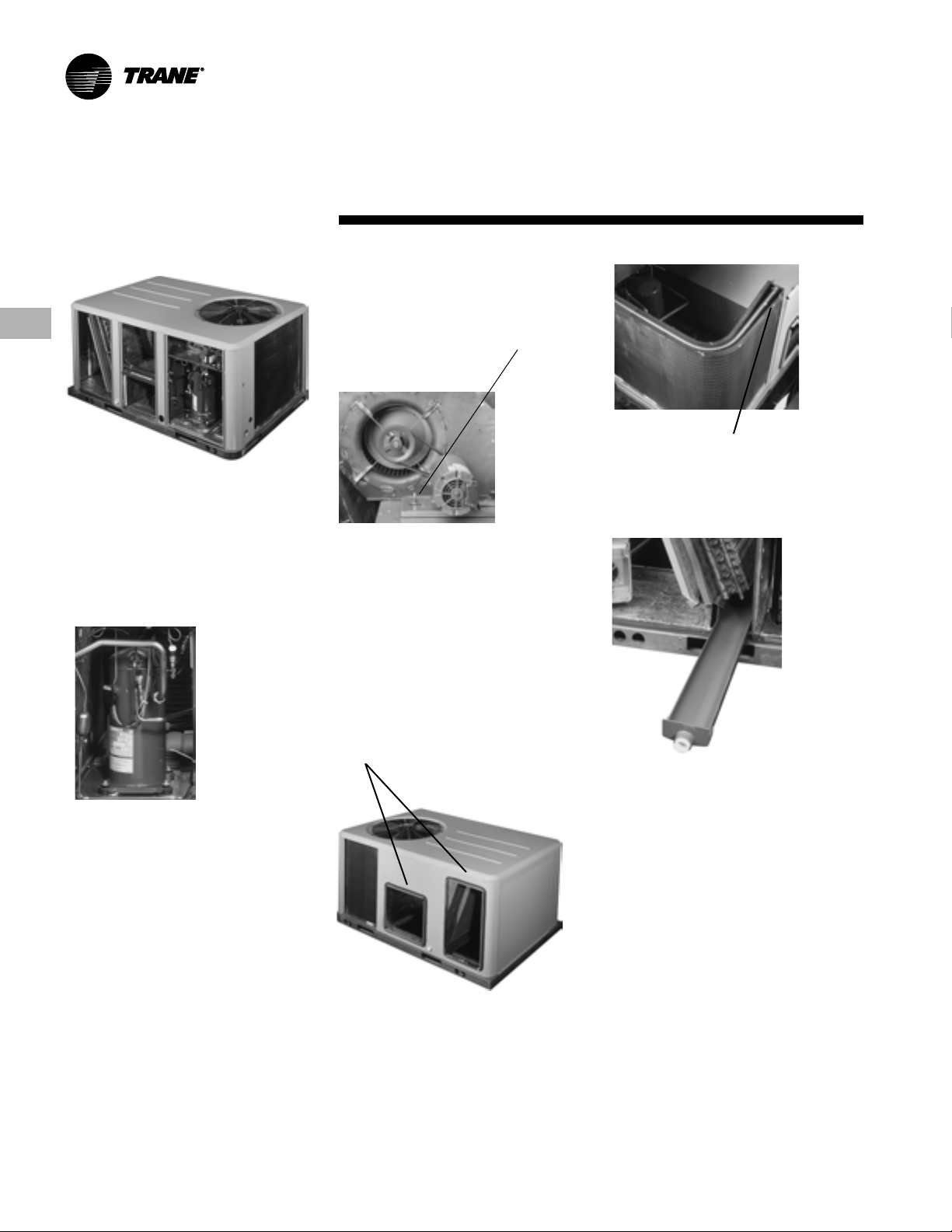
Easy-Adjust Idler Arm
With the Easy-Adjust Idler Arm, the belt
and sheaves can be quickly adjusted
without moving the mounted fan motor.
The result is a major savings in time and
money.
Patented Condenser Coil
Precedent boasts a patented 1+1+1
Hybrid coil, permanently gapped for
easy cleaning.
Colored And Numbered Wiring
You save time and money tracing wires
and diagnosing the unit.
Convertible Units
• The units ship in a downflow
configuration. They can be easily
converted to horizontal by simply
moving two panels.
• Units come complete with horizontal
duct flanges so the contractor doesn’t
have to field fabricate them. These duct
flanges are a time and cost saver.
Compressors
Precedent™ contains the best compressor
technology available to achieve the
highest possible performance. Our
compressor line includes Trane-built
Climatuff
Easy Access Panels
Easy access panels reduce the number of
possible water entry points. Remove two
screws for access to the standardized
internal components and wiring.
Low Ambient Cooling
All Precedent units have cooling
capabilities down to -18°C (0°F) as
standard.
4
™
reciprocating and scrolls.
Unit Base
For added water integrity, Precedent has
a raised 29 mm 1(
unit’s downflow supply and return to
prevent water from blowing into the
ductwork.
1
/8") lip around the
Sloped Drain Pans
Every Precedent unit has a noncorrossive, removable, double-sloped
drain pan that’s easy to clean and
reversible to allow installation of drain
trap on either side of the unit.
Through the Base Condensate
Every unit includes provisions for
through the base condensate drain
connections. This allows the drain to be
connected through the roof curb instead
of a roof penetration.
Foil-Faced Insulation
All panels in the Evaporator section of
the unit have cleanable foil-faced
insulation. All edges are either captured
or sealed to ensure no fibers get into the
airstream.
PKGP-PRC004-EN
Features and
Benefits
Standardized Components
• Components are placed in the same
location on all Precedent
Familiarize yourself with one Precedent
and you are familiar with every
Precedent.
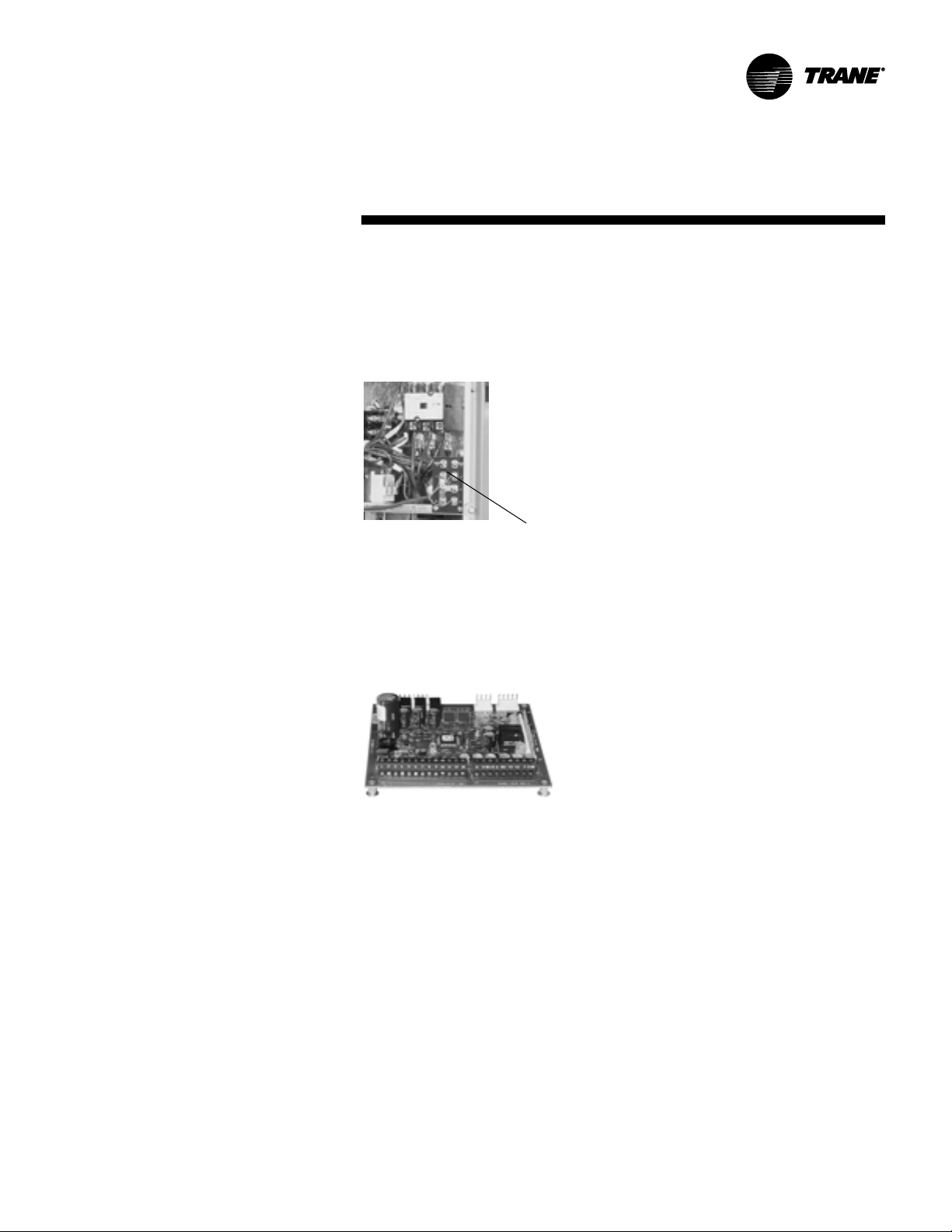
Easy Access Low Voltage Terminal
Board
Precedent’s Low Voltage Terminal Board
is external to the electrical control
cabinet. It is extremely easy to locate and
attach the thermostat wire. This is
another cost and time saving installation
feature.
™
units.
Flexible Applications
• Only two roof curbs for the 5-10 ton
Precedent line…simplifies curb
selection.
• Airflow is outstanding. The Precedent
can replace an older machine with old
ductwork and, in many cases, improve
comfort through better air distribution.
• Belt drive — standard or oversized
supply fan motors meet a wide airflow
range.
• Precedent offers ultimate flexibility.
Options and components are not prepackaged at the factory. Units are built
to order in our standard “shortest in
the industry” ship cycle time.
PKGP-PRC004-EN
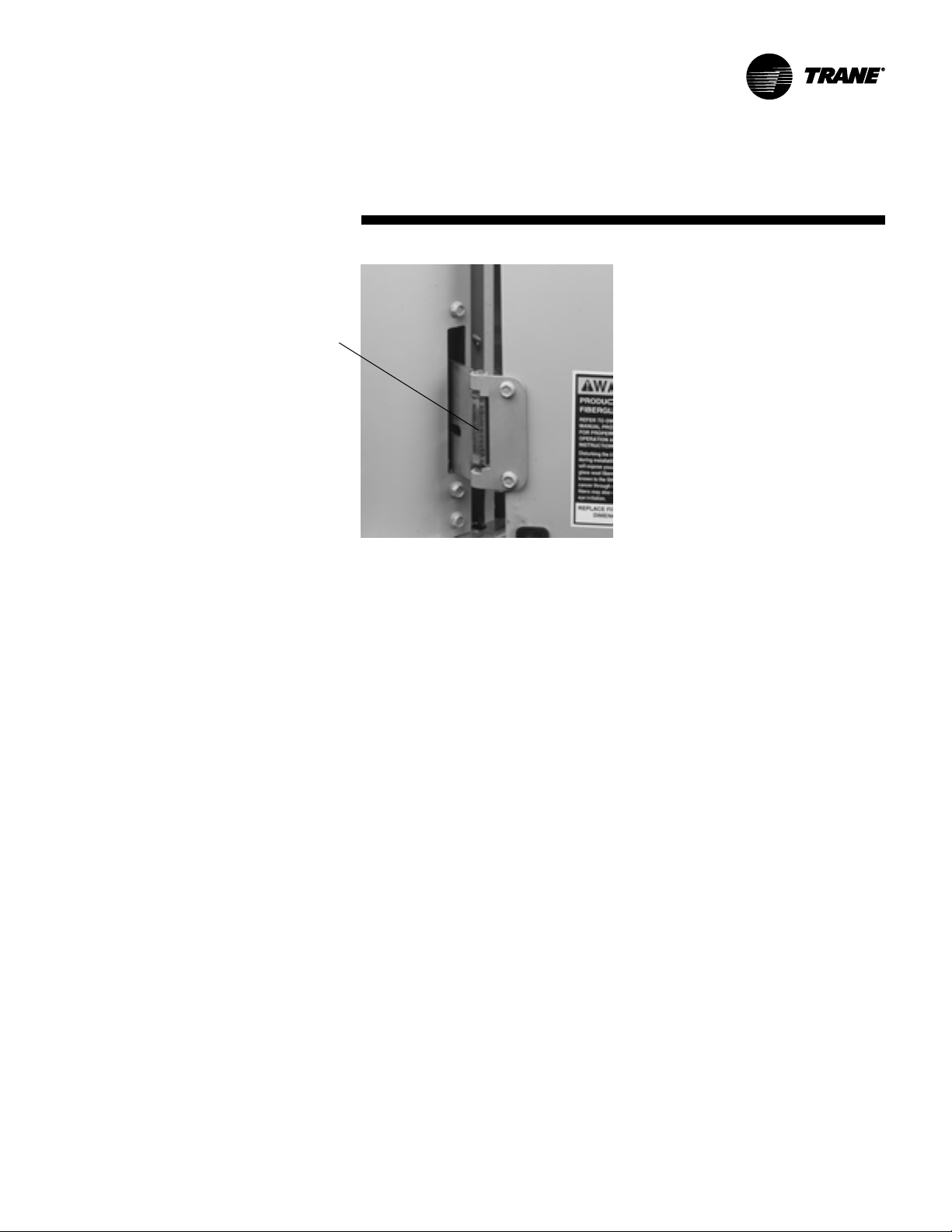
Low Voltage Connections
The wiring of the low voltage
connections to the unit and the zone
sensors is as simple as 1-1, 2-2, and 3-3.
This simplified system makes it easy for
the installer to wire
Single-Side Service
Single-side service is standard on all
Precedent units.
5
Features and
Benefits
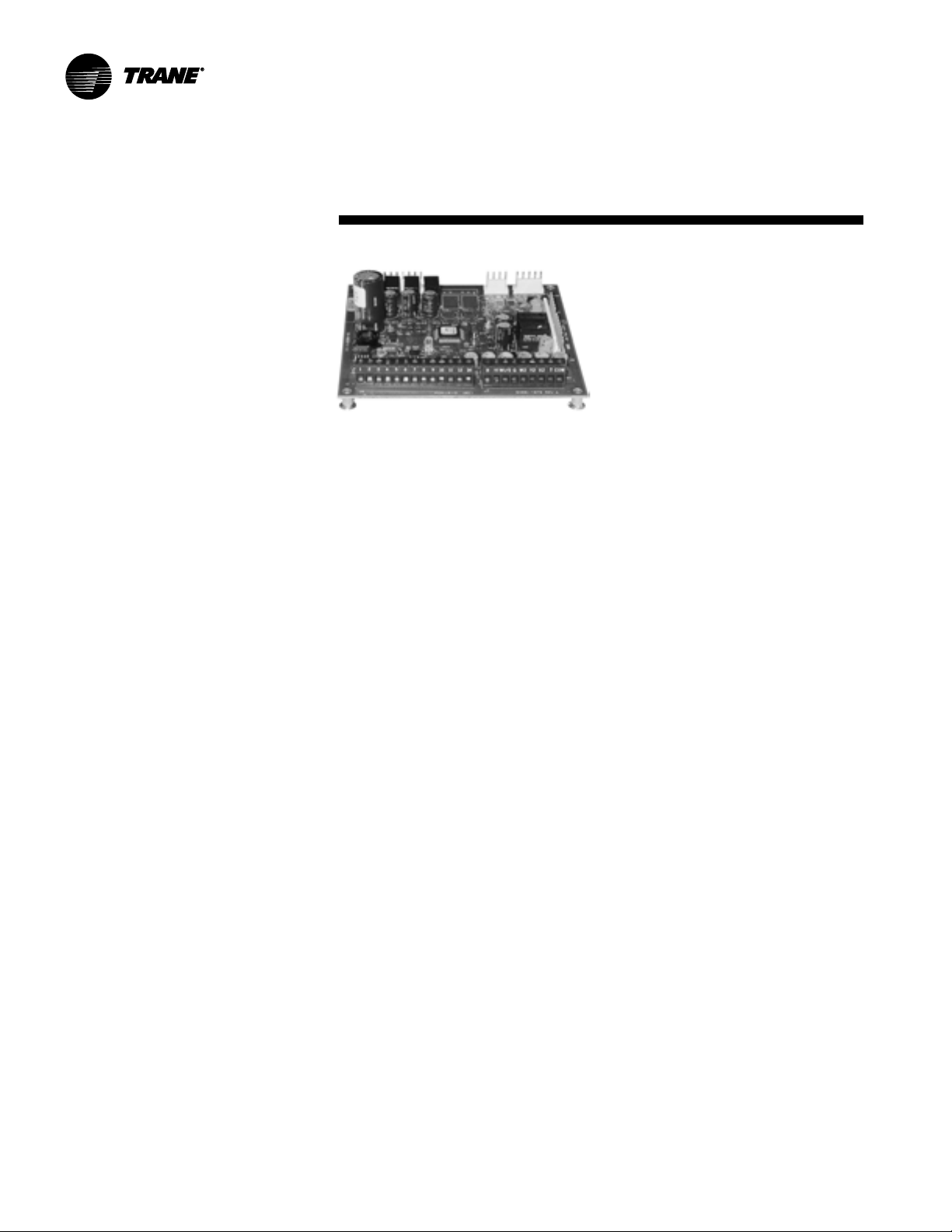
Micro Controls
Several years ago, Trane was the first to
introduce microprocessor controls into
the Light Commercial Market. That
design, along with immeasurable
experience, has provided the technology
for Trane’s second-generation ReliaTel
microprocessor controls.
ReliaTel Micro:
• Provides unit control for heating,
cooling, and ventilating by utilizing
input from sensors that measure
outdoor and indoor temperature.
• Improves quality and reliability through
the use of time-tested microprocessor
controls and logic.
• Prevents the unit from short cycling,
considerably improving compressor
life.
• Ensures that the compressor will run
for a specific amount of time, which
allows oil to return for better
lubrication, enhancing the reliability of
the compressor.
• Reduces the number of components
required to operate the unit, thereby
reducing possibilities for component
failure.
™
• Eliminates the need for field-installed
components with its built-in antishort-cycle timer, time delay relay
and minimum ‘’on’’ time controls.
These controls are factory tested to
assure proper operation.
• Requires no special tools to run the
Precedent unit through its paces
during testing. Simply place a
jumper between Test 1 and Test 2
terminals on the Low Voltage
Terminal Board and the unit will walk
through its operational steps. The
unit automatically returns control to
the zone sensor after stepping
through the test mode a single time,
even if the jumper is left on the unit.
• As long as the unit has power and
the LED is lit, the Micro is
operational. The light indicates that
the Micro is functioning properly.
• Features expanded diagnostic
capabilities when used with Trane’s
Integrated Comfort
• As an energy benefit, softens
electrical ‘’spikes’’ by staging on fans,
compressors and heaters.
• The Intelligent Fallback or Adaptive
Control is a benefit to the building
occupant. If a component goes
astray, the unit will continue to
operate at predetermined
temperature set points.
• Intelligent Anticipation is a standard
feature of the Micro. Functioning
constantly, the Micro and zone
sensors work together in harmony to
provide tight comfort control.
™
systems.
6
PKGP-PRC004-EN
Features and
Benefits
Factory-installed Options
Hinged Access Doors
These doors permit easy access to the
filter, fan/heat, and compressor/control
sections. They reduce the potential roof
damage from screws or sharp access
door corners.
Economizer
Equipped with either dry bulb, reference
or comparative enthalpy sensing, this
feature provides free cooling as the
outdoor temperature and/or humidity
decreases. Economizers, correctly
installed, offer valuable energy savings.
Factory-installed economizers save time
and ensure proper installation.
Phase Monitor
Phase monitor shall provide 100%
protection for motors and compressors
against problems caused by phase loss,
phase imbalance, and phase reversal.
Phase monitor is equipped with an LED
that provides an ON or FAULT indicator.
Clogged Filter/Fan Fail Switches
These sensors allows a zone sensor
service light or Integrated Comfort
system to indicate a dirty filter or a fan
that’s not working. The field installation
charges for these valuable feedback
devices often eliminate them from
consideration. Factory installation can
make such features a good investment.
Comm-3/4 Trane Communication
Interface
Available factory or field-installed. This
module, when applied with the Micro,
easily interfaces with Trane’s Integrated
Comfort
™
system.
The following options round-out the
complete line of Precedent
— 0 - 50% Manual or Motorized
Outside Air
— Discharge Air Sensor
— Electric heaters (available as field-
installed accessories)
— Hail Protection Quality Coil
Guards
— Wide array of Zone Sensors
— Factory built Roof Curb
One of Our Finest Assets:
Trane Sales Representatives are a
Support group that can assist you
with:
— Product
— Application
— Service
— Training
— Special Applications
— Specifications
— Computer Programs and much
more
Precedent has the features and
benefits that make it first class in the
light commercial rooftop market.
Designed with input from field
contractors and engineers, its airflow
performance is outstanding.
Precedent…The same Trane
quality…with added flexibility.
™
options:
PKGP-PRC004-EN
7
Features and
Benefits
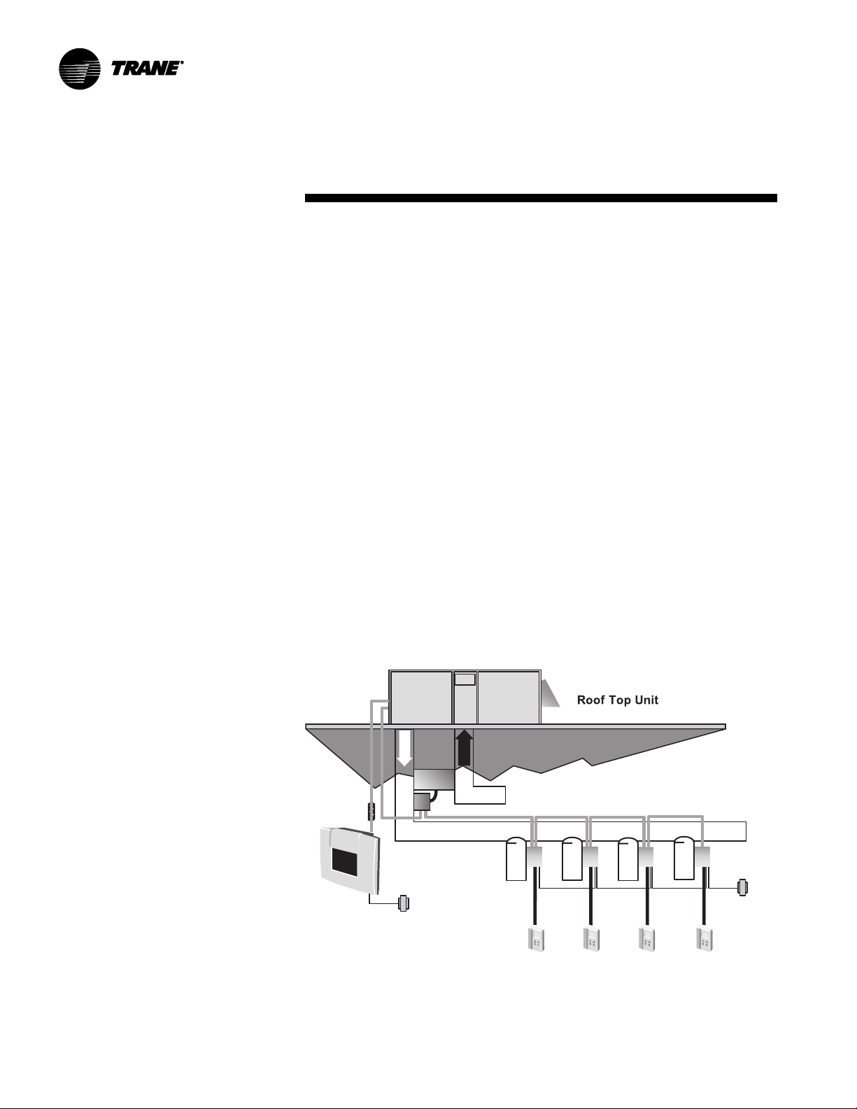
Va riTra c
When Trane’s changeover VAV System
for light commercial applications is
coupled with Precedent, it provides the
latest in technological advances for
comfort management systems and can
allow thermostat control in every zone
served by VariTrac.
Quality And Reliability Testing
• All Precedent
rain tested at the factory to ensure
water integrity.
• Actual shipping tests were performed
to determine packaging requirements.
Units were test shipped around the
country to determine the best
packaging.
• Factory shake and drop tests were
used as part of the package design
process to help assure that the unit
arrives at the job site in top condition.
• Rigging tests include lifting a unit into
the air and letting it drop one foot,
assuring that the lifting lugs and rails
hold up under stress.
VariTrac
™
designs were rigorously
™
• We perform a 100% coil leak test at the
factory. The evaporator and condenser
coils are leak tested at 1,375 kPa (200
psig) and pressure tested to 3,100 kPa
(450 psig).
• All parts are inspected at the point of
final assembly. Sub-standard parts are
identified and rejected immediately.
• Every unit receives a 100% unit run test
before leaving the production line to
make sure it lives up to rigorous Trane
requirements.
We test designs at our factory not on
our customers!
8
PKGP-PRC004-EN

Application Considerations
Application of this product should be
within the cataloged airflow and cooling
considerations.
Low Ambient Cooling
Precedent™ features, as standard, low
ambient cooling down to -18°C (0°F).
Contact your local Trane Representative
for more assistance with low ambient
cooling applications.
Barometric Relief
This product line offers an optional
barometric relief damper for use in
conjunction with economizer option.
This option consists of gravity dampers
which open with increased pressure. As
the building air pressure increases, the
pressure in the unit return air section
also increases, opening the dampers
and relieving the conditioned space.
NOTE: THE EFFECTIVENESS OF
BAROMETRIC RELIEF DAMPER
DURING ECONOMIZING OPERATION
IS SYSTEM RELATED.
PRESSURE DROP OF THE RETURN AIR
SYSTEM SHOULD BE CONSIDERED TO
CONTROL BUILDING PRESSURIZATION.
Condensate Trap
The evaporator is a draw-thru
configuration. A trap must be field
provided prior to start-up on the cooling
cycle.
Clearance Requirements
The recommended clearances identified
with unit dimensions should be
maintained to assure adequate service,
maximum capacity and peak operating
efficiency. Actual clearances which
appear inadequate should be reviewed
with the local Trane sales personnel.
Unit Pitch
These units have reversible sloped
condensate drain pans. Units must be
installed level, any unit slope must be
toward side of unit where condensate
drain is connected.
PKGP-PRC004-EN
9

Selection
Procedure - SI Units
Cooling Capacity
Step 1
Calculate the building’s total and
sensible cooling loads at design
conditions. Use the Trane calculation
form or any other standard accepted
method.
Step 2
Size the equipment using Table PD-1.
Match the cooling loads at design
conditions.
Example: The following are the building
cooling requirements:
A
Electrical Characteristics: 380–415/50/3
B
Summer Design Conditions:
Entering Evaporator Coil: 27 DB/ 19 WB
Outdoor Ambient: 35
C
Total Cooling Load: 17.0 kW
D
Sensible Cooling Load: 11.7 kW
E
Airflow: 3,400 m
External Static Pressure: 130 Pa
F
Downflow Configuration
3
/hr
Table PD-1 shows that a WSC060AD has
a gross cooling capacity of 18.1 kW and
14.7 kW sensible capacity at 35 degree C
ambient and 3,400 m
WB air entering the evaporator.
To find the net cooling capacities, fan
motor heat must be subtracted.
Determine the total unit static pressure:
External Static 130 Pa
Standard Filter 1 in. 37 Pa
Economizer 46 Pa
Supplementary Electric Heat 21 Pa
Total Static Pressure 234 Pa
Note: The Evaporator Fan Performance
Table PD-9 has deducted the pressure
drop for a 25 mm filter already in the
downflow unit.
Therefore, the actual Total Static
Pressure is 234 – 37 = 197 Pa. With 3,400
m3/hr and 197 Pa, Table PD-9 shows 0.75
kW.
Note below the table gives a formula to
calculate Fan Motor Heat,
Fan Motor Heat (kW) =
1.144 x (Fan kW) + 0.132
= 1.144 x 0.75 + 0.132 = 1.0 kW
Net Total Cooling Capacity =
18.1 – 1.0 = 17.1 kW
Net Sensible Cooling Capacity =
14.7 – 1.0 = 13.7 kW
3
/hr with 27 DB/19
Heating Capacity
Step 1
Calculate the building heating load using
the Trane calculation form or other
standard accepted method.
Step 2
Size the equipment using Table PD-5 to
match the heating loads at design
conditions.
A
Total Heating Load: 16 kW
B
Outdoor Ambient (Winter) –9°C DB
C
Indoor Return Temperature: 21°C DB
D
Airflow: 3,400 m3/hr
Use the portion of Table PD-5 for the
WSC060AD to determine capacity at
winter design conditions. The
mechanical heating portion of the heat
pump will provide 8.3 kW.
Step 3
Because 8.3 kW is less than the
building’s required heating capacity at
winter design conditions, a
supplementary heater must be selected.
16 kW – 8.3 kW = 7.7 kW
From Table PD-9, at 380 volts, the 10.9
kW Heater will be adequate to do the
job.
From Table ED-5 select heater
BAYHTRR418A (10.9 kW 380/50/3).
Air Delivery Selection
External static pressure drop through the
air distribution system has been
calculated to be 200 Pa. Enter Table PD-9
for a WSC060AD at 3400 m
Pa static pressure. The standard motor
will give the desired airflow.
Accessory Selection
Select accessories needed to
accommodate the application.
10.9 kW 38.0 MBh
3
/h and 200
10
PKGP-PRC004-EN

Selection
Procedure - IP Units
Cooling Capacity
Step 1
Calculate the building’s total and
sensible cooling loads at design
conditions. Use the Trane calculation
form or any other standard accepted
method.
Step 2
Size the equipment using Table PD-1a.
Match the cooling loads at design
conditions.
Example: The following are the building
cooling requirements:
A
Electrical Characteristics: 380–415/50/3
B
Summer Design Conditions:
Entering Evaporator Coil: 80 DB/ 67 WB
Outdoor Ambient: 95
C
Total Cooling Load: 53 MBh
D
Sensible Cooling Load: 33 MBh
E
Airflow: 2,000 cfm
External Static Pressure: .52 in. w.g.
F
Downflow Configuration
Table PD-1a shows that a WSC060AD
has a gross cooling capacity of 59.0 MBh
and 45.7 MBh sensible capacity at 95
degree ambient and 2,000 cfm with 80
DB/67 WB air entering the evaporator.
To find the net cooling capacities, fan
motor heat must be subtracted.
Determine the total unit static pressure:
External Static 0.52 in.
Standard Filter 1 in. 0.15 in.
Economizer 0.18 in.
Supplementary Electric Heat 0.083 in.
Total Static Pressure 0.933 in.
Note: The Evaporator Fan Performance
Table PD-9a has deducted the pressure
drop for a 1 in. filter already in the
downflow unit.
Therefore, the actual Total Static
Pressure is 0.933 – 0.15 = 0.78. With
2,000 cfm and 0.78 inches, Table PD-9a
shows 1.00 bhp.
Note below the table gives a formula to
calculate Fan Motor Heat,
Fan Motor Heat (MBh) =
2.915 x (Fan bhp) + 0.451
= 2.915 x 1.00 + 0.451 = 3.37 MBh
Net Total Cooling Capacity =
57 – 3.37 = 53.6 MBh
Net Sensible Cooling Capacity =
38 – 3.37 = 34.6 MBh
Heating Capacity
Step 1
Calculate the building heating load using
the Trane calculation form or other
standard accepted method.
Step 2
Size the equipment using Table PD-5a to
match the heating loads at design
conditions.
A
Total Heating Load: 50 MBh
B
Outdoor Ambient (Winter) 17 DB
C
Indoor Return Temperature: 70 DB
D
Airflow: 2,000 cfm
Use the portion of Table PD-5a for the
WSC060AD to determine capacity at
winter design conditions. The
mechanical heating portion of the heat
pump will provide 29.1 MBh.
Step 3
Because 29.1 MBh is less than the
building’s required heating capacity at
winter design conditions, a
supplementary heater must be selected.
50 MBh – 29.1 MBh = 29.9 MBh
From Table PD-9a, at 380 volts, the 38.0
MBh Heater will be adequate to do the
job.
10.9 kW 38.0 MBh
From Table ED-2 select heater
BAYHTRR418A (38.0 MBh at 380 volts).
Air Delivery Selection
External static pressure drop through the
air distribution system has been
calculated to be 0.80 inches of water.
Enter Table PD-9a for a WSC060AD at
2000 cfm and 0.80 static pressure. The
standard motor will give the desired
airflow.
Accessory Selection
Select accessories needed to
accommodate the application.
PKGP-PRC004-EN
11

Model Number Description
W S C 060 A D R O A ** C 0 0 0 0 0 0 0 0 0 0 1
1 2 3 4,5,6 7 8 9 10 11 12,13 14 15 16 17 18 19 20 21 22 23 24 25
Digit 1 - Unit Function
W = Packaged Heat Pump
Digit 2 - Efficiency
S = Standard Efficiency
Digit 3 - Airflow
C = Convertible
Digits 4,5,6 - Nominal Gross Cooling
Capacity (MBh)
kW Tons
060 = 17.6 5
072 = 21.1 6
090 = 26.4 7.5
120 = 35.1 10
Digit 7 - Major Design Sequence
A = First
Digit 8 - Unit Voltage
D = 380–415/50/3
T = 200/50/3
Digit 9 - Unit Controls
R = ReliaTel™ Microprocessor
Digit 10 - Electric Heater
0 = No Electric Heater
Digit 11 - Minor Design Sequence
A = First Sequence
Digits 12,13 - Service Sequence
** = Factory Assigned
Digit 14 - Fresh Air Selection
0 = No Fresh Air
A = Manual Outside Air Damper 0-50%
B = Motorized Outside Air Damper 0-50%
C = Economizer, Dry Bulb 0-100% without
Barometric Relief
D = Economizer, Dry Bulb 0-100% with
Barometric Relief
E = Economizer, Reference Enthalpy
0-100% without Barometric Relief
F = Economizer, Reference Enthalpy
0-100% with Barometric Relief
G = Economizer, Comparative Enthalpy
0-100% without Barometric Relief
H = Economizer, Comparative Enthalpy
0-100% with Barometric Relief
Digit 15 - Supply Fan/Drive Type/Motor
0 = Standard Drive
1 = Oversized Motor
Digit 16 - Hinged Service Access/Filters
0 = Standard Panels/Standard Filters
A = Hinged Access Panels/Standard Filters
B = Standard Panels/50mm (2”) Pleated
Filters
C = Hinged Access Panels/50mm (2”)
Pleated Filters
Digit 17 - Condenser Coil Protection
0 = Standard Coil
1 = Standard Coil with Hail Guard
2 = Epoxy Coated Condenser Coil
3 = Epoxy Coated Condenser Coil
with Hail Guard
Digit18 - Through the Base Provisions
0 = No Through the Base Provisions
Digit 19 - Disconnect/Circuit Breaker/Phase
Monitor (3 phase only)
0 = No Disconnect or Circuit Breaker
3 = Phase Monitor Only (No Disconnect,
No Circuit Breaker)
Digit 20 - Convenience Outlet
0 = No Convenience Outlet
Digit 21 - Communications Options
0 = No Communications Interface
1 = Comm-3/4 Trane Communications
Interface
2 = Comm-5 LonTalk Communications
Interface
Digit 22 - Refrigeration System Option
0 = Standard Refrigeration System
Digit 23 - Refrigeration Controls
0 = No Refrigeration Control
Digit 24 - Smoke Detector
0 = No Smoke Detector
Digit 25 - Monitoring Controls
0 = No Monitoring Control
1 = Clogged Filter Switch
2 = Fan Failure Switch
3 = Discharge Air Sensing Tube
4 = Clogged Filter Switch and Fan Fail
Switch
5 = Clogged Filter Switch and Discharge
Air Sensing Tube
6 = Fan Fail Switch and Discharge Air
Sensing Tube
7 = Clogged Filter and Fan Fail Switches
and Discharge Air Sensing Tube
12
PKGP-PRC004-EN
General Data
Table GD-1 - General Data
Convertible Units Convertible Units Convertible Units Convertible Units
Cooling Performance
Gross Capacity - kW (MBh) 17.3 (59.0) 22.6 (77.0) 27.8 (95.0) 34.6 (118.0)
COP (EER)
Nominal Airflow - m3/h (cfm) 3400 (2000) 4080 (2400) 5100 (3000) 6800 (4000)
Rated Airflow - m
Net Capacity - kW (MBh) 16.7 (57.0) 21.4 (73.0) 26.4 (90.0) 33.1 (113.0)
System Power - kW 6.13 6.46 8.26 11.19
Heating Performance
High Temperature Capacity - kW (MBh) 16.0 (54.5) 19.9 (68.0) 24.0 (82.0) 31.9 (109.0)
1
2
3
/h (cfm) 3400 (2000) 3570 (2100) 4460 (2625) 5950 (3500)
1
COP 3.40 3.45 3.54 3.36
System Power - kW 4.71 5.76 6.78 9.48
Compressor
Number - Type 1-Climatuff Scroll 1-Climatuff Scroll 1-Trane 3-D Scroll 2-Climatuff Scroll
Outdoor Sound Rating - dB
3
Outdoor Coil - Type Lanced Lanced Lanced Lanced
Tube Size - in. OD 0.3125 0.3125 0.3125 0.3125
Face Area - m
Rows / FPI 3 / 17 2 / 17 3 / 17 3 / 17
2
(sq ft) 1.02 (10.96) 1.58 (17.00) 1.58 (17.00) 1.84 (19.83)
Refrigerant Control Expansion Valve Expansion Valve Expansion Valve Expansion Valve
Indoor Coil - Type Lanced Lanced Lanced Lanced
Tube Size OD - in. 0.3125 0.3125 0.3125 0.3125
Face Area - m
Rows / FPI 3 / 16 3 / 16 4 / 16 4 / 16
2
(sq ft) 0.72 (7.71) 0.92 (9.89) 0.92 (9.89) 1.15 (12.36)
Refrigerant Control Short Orifice Short Orifice Short Orifice Short Orifice
Drain Connection No. / Size - in. 1 / 0.75 NPT 1 / 0.75 NPT 1 / 0.75 NPT 1 / 0.75 NPT
Outdoor Fan - Type Propeller Propeller Propeller Propeller
No. Used / Diameter (in.) 1 / 22 1 / 26 1 / 26 1 / 26
Drive Type / No. Speeds Direct / 1 Direct / 1 Direct / 1 Direct / 1
CFM 2900 5100 5200 5800
No. Motors / kW (HP) 1 / 0.30 (0.40) 1 / .56 (0.75) 1 / .56 (0.75) 1 / .56 (0.75)
Motor RPM 950 950 950 950
Belt Drive Indoor Fan - Type FC Centrifugal FC Centrifugal FC Centrifugal FC Centrifugal
No. Used 1 1 1 1
Fan Diameter x Width - mm - in. 280 X 280 (11 x 11) 305 X 305 (12 x 12) 305 X 305 (12 x 12) (381 X 381) 15 x 15
Drvie Type / No. Speeds Belt / Variable Speed Belt / Variable Speed Belt / Variable Speed Belt / Variable Speed
No. Motors 1 1 1 1
Standard Motor Power - kW (HP) 1.1 (1.5) 1.1 (1.5) 1.5 (2.0) 2.2 (3.0)
Oversized Motor Power - kW (HP) - 1.5 (2.0) 2.2 (3.0) Motor RPM - Standard / Oversized 1450 / - 1450 / 1450 1450 / 2850 2850 / Motor Frame Size 56 56 56 56
Filters - Type Furnished Throwaway Throwaway Throwaway Throwaway
(No.) Size Reccommended - mm (2) 508 X 762 X 25 (4) 406 X 635 X 50 (4) 406 X 635 X 50 (4) 508 X 635 X 50
(No.) Size Reccommended - in. (2) 20 X 30 X 1 (4) 16 X 25 X 2 (4) 16 X 25 X 2 (4) 20 X 25 X 2
Refrigerant Charge - kg (lbs) of R-22
NOTES:
1. Cooling Performance is rated at 35.0 C (95 F) ambient, 26.7 C (80 F) entering dry bulb, 19.4 C (67 F) entering wet bulb. Heating Performance israted at 20.0 C (68 F) ambient, 8.3 C
(47 F) entering dry bulb, 6.1 C (43 F) entering wet bulb. Gross capacity does not include the effect of fan motor heat. Net capacity includes the effect of fan motor heat. Units are
suitable for operation to + 20 % of nominal airflow.
2. EER are rated at ARI conditions.
3. Outdoor Sound rating shown is tested in accordance with ARI Standard 270. For more information refer to Performance Data Table “Sound Power Level”.
4. Refrigerant charge is an approcimate value. For a more precise value, see unit nameplate and service literature.
4
WSC060AD,T WSC072AD,T WSC090AD,T WSC120AD,T
2.72 (9.3) 3.31 (11.3) 3.20 (10.9) 3.28 (10.1)
80 85 85 79
3.6 (8.0) 4.3 (9.4) 5.7 (12.5) Circuit 1 - 3.5 (7.7)
Circuit 2 - 3.5 (7.7)
PKGP-PRC004-EN
13
Performance Data
Table PD-1 — Gross Cooling Capacities (kW) WSC060AD,T (SI)
Enter. Ambient Temperature (C)
Dry 30 35 40 45
Bulb Entering Wet Bulb Temperature (C)
3
/h Temp 16 19 22 16 19 22 16 19 22 16 19 22
m
Airflow (C) TGC SHC TGC SHC TGC SHC TGC SHC TGC SHC TGC SHC TGC SHC TGC SHC TGC SHC TGC SHC TGC SHC TGC SHC
3060 24 14.5 13.2 16.6 10.7 18.3 7.6 15.6 13.8 17.7 11.0 19.0 8.0 13.3 12.6 15.3 10.1 17.4 7.2 12.1 12.0 13.9 9.5 16.3 6.6
3400 24 14.9 14.1 16.9 11.3 18.5 7.8 16.1 14.7 18.0 11.5 19.2 8.2 13.7 13.5 15.6 10.4 17.6 7.4 12.5 12.5 14.2 10.1 16.5 6.9
3740 24 15.3 15.0 17.2 11.5 18.7 8.1 16.5 15.6 18.2 12.0 19.3 8.4 14.1 14.1 15.9 11.0 17.8 7.6 12.9 12.9 14.5 10.8 16.7 7.1
4080 24 15.6 15.6 17.4 12.1 18.8 8.3 16.8 16.4 18.4 12.4 19.5 8.6 14.5 14.5 16.1 11.5 17.9 7.9 13.4 13.4 14.7 10.8 16.9 7.3
Notes:
1. All capacities shown are gross and have not considered indoor fan heat. To obtain net cooling, subtract indoor fan heat.
2. TGC = Total Gross Capacity
3. SHC = Sensible Heat Capacity
27 15.3 15.3 16.7 13.4 18.4 10.4 16.3 16.3 17.8 13.9 19.1 10.8 14.3 14.3 15.4 12.8 17.5 10.0 13.3 13.3 14.1 12.2 16.3 9.5
30 16.7 16.7 17.0 16.3 18.5 13.2 17.6 17.6 18.0 16.8 19.3 13.4 15.7 15.7 15.8 15.8 17.5 12.8 14.7 14.7 14.7 14.7 16.4 12.3
33 17.9 17.9 17.9 17.9 18.7 15.9 18.6 18.6 18.6 18.6 19.5 16.0 17.0 17.0 17.0 17.0 17.7 15.6 16.0 16.0 16.0 16.0 16.6 15.2
27 16.0 16.0 17.0 14.2 18.6 10.9 17.0 17.0 18.1 14.7 19.3 11.5 15.0 15.0 15.8 13.6 17.7 10.5 13.9 13.9 14.5 13.0 16.6 10.0
30 17.4 17.4 17.4 17.4 18.8 13.8 18.2 18.2 18.4 17.8 19.5 13.9 16.4 16.4 16.4 16.4 17.8 13.6 15.4 15.4 15.4 15.4 16.7 13.2
33 18.5 18.5 18.5 18.5 19.0 16.7 19.1 19.1 19.1 19.1 19.8 16.7 17.6 17.6 17.6 17.6 18.1 16.6 16.7 16.7 16.7 16.7 17.0 16.3
27 16.6 16.6 17.4 15.0 18.8 11.2 17.5 17.5 18.3 15.4 19.6 11.3 15.6 15.6 16.2 14.5 17.9 11.0 14.4 14.4 14.8 13.9 16.8 10.5
30 17.9 17.9 17.9 17.9 19.0 14.4 18.6 18.6 18.7 18.7 19.7 14.4 17.0 17.0 17.0 17.0 18.0 14.2 15.9 15.9 15.9 15.9 16.9 13.9
33 18.9 18.9 18.9 18.9 19.3 17.5 19.5 19.5 19.5 19.5 20.0 17.4 18.1 18.1 18.1 18.1 18.4 17.5 17.2 17.2 17.2 17.2 17.3 17.2
27 17.1 17.1 17.6 15.8 18.9 11.6 18.0 18.0 18.5 16.0 19.7 11.8 16.1 16.1 16.5 15.3 18.1 11.4 14.9 14.9 15.1 14.7 17.0 11.0
30 18.3 18.3 18.3 18.3 19.2 14.9 19.0 19.0 19.0 19.0 19.9 14.8 17.4 17.4 17.4 17.4 18.2 14.9 16.4 16.4 16.4 16.4 17.1 14.6
33 19.2 19.2 19.2 19.2 19.5 18.2 19.8 19.8 19.8 19.8 20.2 17.9 18.5 18.5 18.5 18.5 18.6 18.2 17.6 17.6 17.6 17.6 17.6 17.6
Table PD-1a — Gross Cooling Capacities (MBH) WSC060AD,T (IP)
Enter. Ambient Temperature (F)
Dry 85 95 105 115
CFM Temp 61 67 73 61 67 73 61 67 73 61 67 73
Airflow (F) TGC SHC TGC SHC TGC SHC TGC SHC TGC SHC TGC SHC TGC SHC TGC SHC TGC SHC TGC SHC TGC SHC TGC SHC
1800 75 54.0 46.5 61.5 35.8 65.9 24.0 49.6 44.2 57.7 34.7 63.5 22.6 45.0 41.9 52.8 32.5 60.3 21.1 40.3 39.5 47.6 30.2 56.2 19.4
2000 75 55.5 49.5 62.4 38.3 66.5 24.4 51.0 47.2 58.8 35.6 64.1 23.1 46.4 44.9 54.0 34.4 61.0 21.6 41.6 41.6 48.6 32.1 57.0 19.9
2200 75 56.8 52.4 63.1 39.9 66.9 24.8 52.3 50.1 59.6 37.2 64.5 23.5 47.3 47.3 54.9 35.1 61.5 22.0 43.1 43.1 49.5 34.0 57.6 20.4
2400 75 57.9 55.2 63.6 41.2 67.2 25.2 53.5 52.9 60.3 38.8 64.9 23.9 48.9 48.9 55.7 38.1 61.9 22.4 44.5 44.5 50.3 34.3 58.1 20.8
Notes:
1. All capacities shown are gross and have not considered indoor fan heat. To obtain net cooling, subtract indoor fan heat.
2. TGC = Total Gross Capacity
3. SHC = Sensible Heat Capacity
Bulb Entering Wet Bulb Temperature (F)
80 55.3 55.3 61.7 44.9 66.5 33.3 51.8 51.8 57.9 43.1 64.0 31.9 48.0 48.0 53.1 40.9 60.6 30.2 44.0 44.0 47.9 38.5 56.4 28.4
85 59.5 59.5 62.2 53.8 67.1 42.4 56.1 56.1 58.5 52.3 64.3 40.4 52.3 52.3 54.0 50.2 60.9 39.3 48.4 48.4 49.1 47.9 56.6 37.4
90 62.9 62.9 63.3 62.7 67.6 49.1 60.1 60.1 60.1 60.1 64.8 48.8 56.6 56.6 56.6 56.6 61.2 47.9 52.8 52.8 52.8 52.8 57.0 46.4
80 57.7 57.7 62.6 47.1 67.2 34.4 54.1 54.1 59.0 45.7 64.6 33.2 50.1 50.1 54.4 43.5 61.3 31.6 46.0 46.0 49.1 41.2 57.2 29.8
85 61.6 61.6 63.4 56.8 68.0 42.9 58.5 58.5 59.9 55.8 65.0 42.0 54.7 54.7 55.5 53.9 61.6 41.1 50.6 50.6 50.6 50.6 57.4 39.7
90 64.8 64.8 64.8 64.8 68.3 50.9 62.1 62.1 62.1 62.1 65.6 51.1 58.9 58.9 58.9 58.9 62.2 50.6 55.1 55.1 55.1 55.1 58.0 49.4
80 59.7 59.7 63.4 49.2 67.7 35.1 56.1 56.1 59.9 48.1 64.9 35.4 52.1 52.1 55.4 46.1 61.9 32.9 47.8 47.8 50.2 43.8 57.9 31.1
85 63.2 63.2 64.3 59.5 68.5 44.1 60.3 60.3 61.0 58.9 65.6 45.3 56.7 56.7 56.7 56.7 62.3 42.9 52.7 52.7 52.6 52.6 58.1 41.7
90 66.2 66.2 66.1 66.1 69.3 53.4 63.7 63.7 63.6 63.6 66.3 53.1 60.6 60.6 60.6 60.6 63.0 53.0 57.0 57.0 57.0 57.0 58.9 52.2
80 61.2 61.2 64.1 51.1 68.1 35.7 57.8 57.8 60.7 50.3 65.9 34.3 53.8 53.8 56.3 48.6 62.3 33.8 49.4 49.4 51.2 46.3 58.4 32.4
85 64.5 64.5 65.1 61.9 69.0 45.2 61.7 61.7 62.0 61.8 66.1 44.8 58.3 58.3 58.3 58.3 62.8 44.5 54.3 54.3 54.3 54.3 58.8 43.7
90 67.2 67.2 67.2 67.2 69.8 54.9 64.9 64.9 64.9 64.9 66.9 55.0 61.9 61.9 61.9 61.9 63.7 55.2 58.5 58.5 58.5 58.5 59.7 54.8
14
PKGP-PRC004-EN
Performance
Data
Table PD-2 — Gross Cooling Capacities (kW) WSC072AD,T (SI)
Enter. Ambient Temperature (C)
Dry 30 35 40 45
Bulb Entering Wet Bulb Temperature (C)
3
/h Temp 16 19 22 16 19 22 16 19 22 16 19 22
m
Airflow (C) TGC SHC TGC SHC TGC SHC TGC SHC TGC SHC TGC SHC TGC SHC TGC SHC TGC SHC TGC SHC TGC SHC TGC SHC
3670 24 20.3 18.1 22.7 14.4 23.9 10.2 19.0 17.4 21.7 14.0 23.6 9.9 17.6 16.7 20.2 13.4 22.9 9.6 16.1 16.0 18.6 12.7 21.7 9.2
4080 24 20.9 19.3 23.0 15.1 24.1 10.4 19.5 18.6 22.2 14.6 23.8 10.2 18.1 17.9 20.7 14.0 23.1 9.8 16.7 16.7 19.0 13.5 22.1 9.5
4490 24 21.4 20.4 23.2 15.6 24.2 10.7 20.1 19.8 22.5 15.3 23.9 10.4 18.7 18.7 21.1 14.7 23.3 10.1 17.3 17.3 19.3 14.3 22.3 9.7
4900 24 21.9 21.6 23.4 16.1 24.3 10.8 20.5 20.5 22.7 15.9 24.0 10.6 19.3 19.3 21.4 15.4 23.4 10.4 17.9 17.9 19.7 15.1 22.5 10.0
Notes:
1. All capacities shown are gross and have not considered indoor fan heat. To obtain net cooling, subtract indoor fan heat.
2. TGC = Total Gross Capacity
3. SHC = Sensible Heat Capacity
27 21.2 21.2 22.8 17.9 24.2 13.6 20.1 20.1 21.8 17.6 23.7 13.6 19.0 19.0 20.4 17.0 22.9 13.3 17.7 17.7 18.8 16.3 21.7 12.9
30 22.6 22.6 23.1 21.5 24.4 16.7 21.9 21.9 22.2 21.5 23.8 16.8 20.8 20.8 20.9 20.9 23.0 16.8 19.5 19.5 19.5 19.5 21.8 16.5
33 23.7 23.7 23.7 23.7 24.6 19.9 23.2 23.2 23.2 23.2 24.1 20.2 22.4 22.4 22.4 22.4 23.2 20.4 21.3 21.3 21.3 21.3 22.1 20.3
27 22.1 22.1 23.1 18.8 24.3 13.8 21.0 21.0 22.3 18.7 23.9 13.9 19.8 19.8 20.9 18.2 23.2 13.9 18.6 18.6 19.3 17.5 22.1 13.5
30 23.3 23.3 23.5 22.5 24.6 17.1 22.7 22.7 22.6 22.6 24.1 17.5 21.7 21.7 21.7 21.7 23.3 17.7 20.5 20.5 20.5 20.5 22.2 17.6
33 24.2 24.2 24.2 24.2 24.8 20.5 23.8 23.8 23.8 23.8 24.4 21.0 23.1 23.1 23.1 23.1 23.6 21.5 22.2 22.2 22.2 22.2 22.5 21.5
27 22.6 22.6 23.4 19.5 24.5 14.2 21.8 21.8 22.6 19.7 24.2 14.4 20.6 20.6 21.3 19.3 23.4 14.3 19.3 19.3 19.8 18.6 22.4 14.2
30 23.7 23.7 23.8 23.4 24.8 17.7 23.2 23.2 23.2 23.2 24.3 18.1 22.4 22.4 22.4 22.4 23.6 18.5 21.2 21.2 21.2 21.2 22.5 18.5
33 24.5 24.5 24.5 24.5 25.1 21.2 24.2 24.2 24.2 24.2 24.6 21.8 23.6 23.6 23.6 23.6 23.9 22.4 22.8 22.8 22.8 22.8 23.0 22.7
27 23.1 23.1 23.6 20.2 24.6 14.4 22.4 22.4 22.9 20.6 24.2 14.6 21.3 21.3 21.8 20.4 23.6 14.8 20.0 20.0 20.2 19.7 22.5 14.7
30 24.0 24.0 24.0 24.0 24.9 18.1 23.6 23.6 23.6 23.6 24.4 18.6 22.9 22.9 22.9 22.9 23.8 19.1 22.0 22.0 22.0 22.0 22.8 19.4
33 24.8 24.8 24.8 24.8 25.2 21.7 24.5 24.5 24.5 24.5 24.8 22.4 24.0 24.0 24.0 24.0 24.2 23.2 23.3 23.3 23.3 23.3 23.3 23.3
Table PD-2a — Gross Cooling Capacities (MBH) WSC072AD,T (IP)
Enter. Ambient Temperature (F)
Dry 85 95 105 115
CFM Temp 61 67 73 61 67 73 61 67 73 61 67 73
Airflow (F) TGC SHC TGC SHC TGC SHC TGC SHC TGC SHC TGC SHC TGC SHC TGC SHC TGC SHC TGC SHC TGC SHC TGC SHC
2160 75 70.1 61.0 78.5 46.7 82.3 30.5 65.0 58.4 75.5 45.1 81.3 29.5 59.6 55.8 70.0 43.2 79.0 28.3 53.9 53.1 63.6 40.5 75.2 26.9
2400 75 72.0 64.9 79.4 48.9 82.8 31.0 66.8 62.4 76.7 47.2 81.8 30.0 61.4 59.8 71.5 45.0 79.7 28.8 55.7 55.7 65.0 43.0 76.2 27.5
2640 75 73.5 68.6 79.9 49.2 83.2 31.4 68.6 66.3 77.6 49.1 82.2 30.5 62.9 62.9 72.7 47.9 80.2 29.3 57.9 57.9 66.2 45.3 76.8 27.9
2880 75 75.0 72.4 80.5 50.4 83.5 31.9 70.2 70.2 78.2 51.7 82.5 31.0 65.0 65.0 73.7 50.2 80.6 29.8 59.8 59.8 67.2 47.7 77.4 28.4
Notes:
1. All capacities shown are gross and have not considered indoor fan heat. To obtain net cooling, subtract indoor fan heat.
2. TGC = Total Gross Capacity
3. SHC = Sensible Heat Capacity
Bulb Entering Wet Bulb Temperature (F)
80 72.0 72.0 78.8 57.5 83.2 41.7 68.0 68.0 75.7 56.9 81.8 41.4 63.6 63.6 70.3 54.6 79.4 40.1 58.9 58.9 64.0 51.9 75.3 38.7
85 76.7 76.7 79.5 68.6 84.1 51.1 73.5 73.5 76.4 68.7 82.4 51.6 69.3 69.3 71.4 66.6 79.6 51.3 64.6 64.6 65.5 64.0 75.4 50.3
90 80.2 80.2 80.6 79.2 84.9 60.6 78.1 78.1 78.1 78.1 82.9 61.4 74.8 74.8 74.8 74.8 80.1 62.2 70.3 70.3 70.3 70.3 75.8 61.9
80 75.0 75.0 79.8 59.9 83.7 42.4 71.1 71.1 77.0 60.1 82.6 42.5 66.5 66.5 71.9 58.1 80.1 41.8 61.6 61.6 65.6 55.4 76.3 40.4
85 78.9 78.9 80.6 71.7 84.6 52.2 76.5 76.5 77.9 72.6 83.4 53.4 72.4 72.4 73.3 71.4 80.5 53.5 67.6 67.6 67.6 67.6 76.5 53.2
90 81.9 81.9 81.8 81.8 85.5 62.3 80.2 80.2 80.2 80.2 84.2 64.5 77.5 77.5 77.4 77.4 81.2 65.2 73.5 73.5 73.5 73.5 77.1 65.5
80 77.0 77.0 80.6 62.0 84.1 43.0 73.6 73.6 78.0 62.8 83.1 43.3 69.1 69.1 73.3 61.4 80.7 43.6 64.0 64.0 67.1 58.9 77.1 42.0
85 80.4 80.4 81.5 74.3 85.1 53.3 78.4 78.4 79.2 76.2 84.0 54.9 75.2 75.2 75.1 75.1 81.2 55.4 70.3 70.3 70.3 70.3 77.3 55.6
90 83.0 83.0 83.0 83.0 86.0 63.8 81.8 81.8 81.8 81.8 84.9 66.5 79.4 79.4 79.4 79.4 82.0 67.8 76.0 76.0 76.0 76.0 78.2 68.9
80 78.5 78.5 81.2 63.8 84.5 43.5 75.9 75.9 78.9 65.4 83.5 44.1 71.4 71.4 74.6 64.9 81.2 44.2 66.2 66.2 68.4 62.3 77.7 43.6
85 81.5 81.5 82.2 76.7 85.4 54.3 79.9 79.9 80.3 79.3 84.4 56.2 77.1 77.1 77.1 77.1 81.8 57.2 72.5 72.5 72.5 72.5 78.1 57.9
90 83.9 83.9 83.9 83.9 86.4 65.2 82.9 82.9 82.9 82.9 85.4 68.3 80.8 80.8 80.8 80.8 82.7 70.2 77.6 77.6 77.6 77.6 79.1 71.9
PKGP-PRC004-EN
15
Performance
Data
Table PD-3 — Gross Cooling Capacities (kW) WSC090AD,T (SI)
Enter. Ambient Temperature (C)
Dry 30 35 40 45
Bulb Entering Wet Bulb Temperature (C)
3
/h Temp 16 19 22 16 19 22 16 19 22 16 19 22
m
Airflow (C) TGC SHC TGC SHC TGC SHC TGC SHC TGC SHC TGC SHC TGC SHC TGC SHC TGC SHC TGC SHC TGC SHC TGC SHC
4590 24 25.5 22.7 28.1 18.0 29.5 12.6 23.7 21.8 26.9 17.4 29.0 12.3 21.9 21.0 25.1 16.6 28.1 11.9 20.5 16.8 20.7 12.4 20.8 9.3
5100 24 26.1 24.1 28.4 18.7 29.7 12.9 24.4 23.3 27.4 18.2 29.2 12.6 22.6 22.5 25.6 17.5 28.4 12.2 20.4 16.9 20.7 12.5 20.8 9.3
5610 24 26.7 25.6 28.7 19.0 29.8 13.3 25.0 24.8 27.7 19.0 29.4 12.9 23.2 23.2 26.0 18.3 28.6 12.6 20.6 17.3 20.8 12.6 20.9 9.3
6120 24 27.2 26.8 28.9 19.6 29.9 13.4 25.6 25.6 28.0 20.3 29.5 13.3 23.9 23.9 26.3 19.7 28.8 12.9 22.3 22.3 24.3 19.0 27.6 12.5
Notes:
1. All capacities shown are gross and have not considered indoor fan heat. To obtain net cooling, subtract indoor fan heat.
2. TGC = Total Gross Capacity
3. SHC = Sensible Heat Capacity
27 26.5 26.5 28.2 22.3 29.8 16.8 25.2 25.2 27.1 22.1 29.2 17.0 23.7 23.7 25.3 21.3 28.2 16.5 20.8 19.8 21.0 14.8 21.1 11.4
30 28.1 28.1 28.6 26.6 30.1 20.7 27.2 27.2 27.5 26.8 29.4 21.0 25.9 25.9 25.9 25.9 28.3 21.0 21.2 21.2 21.4 17.4 21.5 13.4
33 29.3 29.3 29.3 29.3 30.5 24.7 28.7 28.7 28.7 28.7 29.6 25.0 27.8 27.8 27.8 27.8 28.6 25.3 21.6 21.6 21.7 19.9 21.9 15.6
27 27.4 27.4 28.6 23.2 30.0 17.2 26.2 26.2 27.6 23.3 29.5 17.4 24.7 24.7 25.9 22.7 28.5 17.3 20.8 20.0 21.1 15.0 21.2 11.4
30 28.8 28.8 29.0 27.9 30.4 21.3 28.1 28.1 28.0 28.0 29.8 21.9 27.0 27.0 27.0 27.0 28.7 22.0 21.2 21.2 21.4 17.7 21.6 13.6
33 29.9 29.9 29.9 29.9 30.7 25.4 29.4 29.4 29.4 29.4 30.1 26.3 28.6 28.6 28.6 28.6 29.1 26.6 21.6 21.6 21.8 20.2 22.0 15.8
27 28.1 28.1 28.9 24.1 30.2 17.5 27.1 27.1 28.0 24.4 29.7 17.8 25.6 25.6 26.4 24.0 28.7 17.8 20.9 20.4 21.1 15.2 21.2 11.5
30 29.3 29.3 29.4 28.9 30.6 21.8 28.7 28.7 28.7 28.7 30.0 22.6 27.7 27.7 27.7 27.7 29.0 22.9 21.4 21.4 21.5 18.0 21.6 13.7
33 30.2 30.2 30.2 30.2 30.9 26.1 29.8 29.8 29.8 29.8 30.4 27.2 29.1 29.1 29.1 29.1 29.4 27.7 21.8 21.8 21.9 20.5 22.0 15.9
27 28.5 28.5 29.2 24.9 30.3 17.8 27.7 27.7 28.3 25.4 29.9 18.2 26.4 26.4 27.0 25.4 29.0 18.4 24.8 24.8 25.1 24.6 27.7 18.3
30 29.6 29.6 29.6 29.6 30.7 22.3 29.1 29.1 29.1 29.1 30.2 23.2 28.3 28.3 28.3 28.3 29.3 23.7 27.1 27.1 27.1 27.1 28.0 24.0
33 30.5 30.5 30.5 30.5 31.1 26.8 30.2 30.2 30.2 30.2 30.7 28.0 29.6 29.6 29.6 29.6 29.7 28.7 28.7 28.7 28.7 28.7 28.7 28.7
Table PD-3a — Gross Cooling Capacities (MBH) WSC090AD,T (IP)
Enter. Ambient Temperature (F)
Dry 85 95 105 115
CFM Temp 61 67 73 61 67 73 61 67 73 61 67 73
Airflow (F) TGC SHC TGC SHC TGC SHC TGC SHC TGC SHC TGC SHC TGC SHC TGC SHC TGC SHC TGC SHC TGC SHC TGC SHC
2700 75 87.8 76.5 97.1 58.3 101.4 37.7 81.1 73.3 93.3 56.2 99.9 36.5 74.3 70.1 86.7 54.3 97.1 35.0 70.3 57.6 71.2 40.6 71.5 28.7
3000 75 89.9 81.2 97.8 59.7 102.0 38.3 83.4 78.2 94.6 58.6 100.6 37.1 76.5 75.0 88.3 57.2 97.8 35.6 70.5 58.6 71.4 41.0 71.7 29.3
3300 75 91.9 85.9 98.6 61.8 102.4 39.0 85.5 83.0 95.6 62.2 101.0 37.7 78.3 78.3 89.7 58.7 98.5 36.3 70.8 59.6 71.6 41.4 71.9 29.1
3600 75 93.4 89.8 99.2 63.4 102.8 39.5 86.9 86.9 96.5 64.9 101.5 38.4 80.8 80.8 91.1 61.4 99.0 36.9 71.0 60.5 71.7 41.8 72.0 29.1
Notes:
1. All capacities shown are gross and have not considered indoor fan heat. To obtain net cooling, subtract indoor fan heat.
2. TGC = Total Gross Capacity
3. SHC = Sensible Heat Capacity
Bulb Entering Wet Bulb Temperature (F)
80 90.1 90.1 97.5 71.3 102.5 52.9 85.0 85.0 93.6 70.9 100.7 51.5 79.4 79.4 87.1 68.3 97.6 49.8 71.3 67.7 72.3 48.5 72.7 35.8
85 95.4 95.4 98.3 84.9 103.6 63.1 91.7 91.7 94.5 85.4 101.8 64.2 86.4 86.4 88.5 83.4 97.9 63.8 72.6 72.6 73.4 56.8 73.9 42.3
90 99.3 99.3 99.8 97.9 104.7 74.9 96.7 96.7 96.7 96.7 102.5 76.8 93.0 93.0 93.0 93.0 98.6 77.4 74.0 74.0 74.5 65.1 75.1 48.9
80 93.4 93.4 98.6 74.0 103.1 52.4 88.6 88.6 95.0 74.5 101.6 52.6 82.9 82.9 88.9 72.5 98.5 51.9 71.6 68.9 72.5 49.1 72.9 36.0
85 97.8 97.8 99.7 88.5 104.3 64.5 94.7 94.7 96.3 90.1 102.7 66.1 89.9 89.9 91.1 89.4 99.1 66.5 73.0 73.0 73.7 57.7 74.2 42.7
90 101.2 101.2 101.2 101.1 105.5 76.9 99.1 99.1 99.1 99.1 103.7 79.9 95.8 95.8 95.8 95.7 99.8 80.9 74.4 74.4 74.8 66.1 75.4 49.5
80 95.5 95.5 99.5 76.4 103.6 53.1 91.6 91.6 96.2 77.9 102.2 53.6 86.0 86.0 90.7 76.8 99.2 54.2 71.9 69.9 72.7 49.7 73.1 36.2
85 99.4 99.4 100.7 91.5 104.9 65.7 96.9 96.9 97.8 94.3 103.3 67.8 93.1 93.1 93.0 93.0 100.0 69.1 73.3 73.3 73.9 58.5 74.3 43.0
90 102.5 102.5 102.5 102.5 106.1 78.7 100.9 100.9 100.9 100.9 104.5 82.3 97.9 97.9 97.9 97.9 100.8 84.1 74.7 74.7 75.0 67.1 75.6 50.0
80 97.1 97.1 100.2 78.6 104.1 53.7 93.9 93.9 97.2 80.9 102.7 54.4 88.5 88.5 92.2 80.8 99.9 54.9 72.1 70.9 72.9 50.2 73.2 36.4
85 100.7 100.7 101.5 94.2 105.3 66.9 98.6 98.6 99.0 97.9 103.9 69.4 95.0 95.0 95.0 95.0 100.9 71.6 73.5 73.5 74.0 59.3 74.5 43.3
90 103.5 103.5 103.5 103.5 106.6 80.4 102.1 102.1 102.1 102.1 105.1 84.5 99.6 99.6 99.6 99.6 102.1 87.8 74.9 74.9 75.2 68.0 75.8 50.5
16
PKGP-PRC004-EN
Loading...