


satellite pro s200
Table of contents
 Loading...
Toshiba Personal Computer
TECRA A9 Series
( TECRA S5 / TECRA P5 /Satellite Pro S200 )
Maintenace Manual
TOSHIBA CORPORATION
File Number 960-633
[CONFIDENTIAL]

Copyright
© 2007 by Toshiba Corporation. All rights reserved. Under the copyright laws, this manual
cannot be reproduced in any form without the prior written permission of Toshiba. No patent
liability is assumed with respect to the use of the information contained herein.
Toshiba Personal Computer TECRA A9,S5,P5, Satellite Pro S200Maintenance Manual
First edition April 2007
Disclaimer
The information presented in this manual has been reviewed and validated for accuracy. The
included set of instructions and descriptions are accurate for the TECRA A9,S5,P5 ,Satellite
Pro S200 at the time of this manual's production. However, succeeding computers and
manuals are subject to change without notice. Therefore, Toshiba assumes no liability for
damages incurred directly or indirectly from errors, omissions, or discrepancies between any
succeeding product and this manual.
Trademarks
IBM is a registered trademark and IBM PC is a trademark of International Business
Machines Corporation.
Intel, Intel SpeedStep, Intel Core and Centrino are trademarks or registered trademarks of
Intel Corporation or its subsidiaries in the United States and other countries/regions.
Windows and Microsoft are registered trademarks of Microsoft Corporation.
Photo CD is a trademark of Eastman Kodak.
Sonic RecordNow! is a registered trademark of Sonic Solutions.
Bluetooth is a trademark owned by its proprietor and used by TOSHIBA under license.
i.LINK is trademark and registered trademark of Sony Corporation.
InterVideo and WinDVD are registered trademarks of InterVideo Inc. WinDVD Creator is
trademark of InterVideo Inc.
Other trademarks and registered trademarks not listed above may be used in this manual.
ii [CONFIDENTIAL] TECRA A9(S5/P5/S200) Maintenance Manual (960-633)
Preface
This maintenance manual describes how to perform hardware service maintenance for the
Toshiba Personal Computer TECRA A9,S5,P5,Satellite Pro S200.
The procedures described in this manual are intended to help service technicians isolate
faulty Field Replaceable Units (FRUs) and replace them in the field.
SAFETY PRECAUTIONS
Four types of messages are used in this manual to bring important information to your
attention. Each of these messages will be italicized and identified as shown below.
DANGER: “Danger” indicates the existence of a hazard that could result in death or
serious bodily injury, if the safety instruction is not observed.
WARNING: “Warning” indicates the existence of a hazard that could result in bodily
injury, if the safety instruction is not observed.
CAUTION: “Caution” indicates the existence of a hazard that could result in property
damage, if the safety instruction is not observed.
NOTE: “Note” contains general information that relates to your safe maintenance
service.
Improper repair of the computer may result in safety hazards. Toshiba requires service
technicians and authorized dealers or service providers to ensure the following safety
precautions are adhered to strictly.
Be sure to fasten screws securely with the right screwdriver. If a screw is not fully
fastened, it could come loose, creating a danger of a short circuit, which could cause
overheating, smoke or fire.
If you replace the battery pack or RTC battery, be sure to use only the same model
battery or an equivalent battery recommended by Toshiba. Installation of the wrong
battery can cause the battery to explode.
TECRA A9(S5/P5/S200) Maintenance Manual (960-633)[CONFIDENTIAL] iii

The manual is divided into the following parts:
Chapter 1 Hardware Overview describes the TECRA A9,S5,P5, Satellite Pro
S200 system unit and each FRU.
Chapter 2 Troubleshooting Procedures explains how to diagnose and resolve
FRU problems.
Chapter 3 Test and Diagnostics describes how to perform test and diagnostic
operations for maintenance service.
Chapter 4 Replacement Procedures describes the removal and replacement of the
FRUs.
Appendices The appendices describe the following:
Handling the LCD module
Board layout
Pin assignments
Keyboard scan/character codes
Key layout
Wiring diagrams
BIOS rewrite procedures
EC/KBC rewrite procedures
Reliability
iv [CONFIDENTIAL] TECRA A9(S5/P5/S200) Maintenance Manual (960-633)

Conventions
This manual uses the following formats to describe, identify, and highlight terms and
operating procedures.
Acronyms
On the first appearance and whenever necessary for clarification acronyms are enclosed in
parentheses following their definition. For example:
Read Only Memory (ROM)
Keys
Keys are used in the text to describe many operations. The key top symbol as it appears on
the keyboard is printed in boldface type.
Key operation
Some operations require you to simultaneously use two or more keys. We identify such
operations by the key top symbols separated by a plus (+) sign. For example, Ctrl + Pause
(Break) means you must hold down Ctrl and at the same time press Pause (Break). If
three keys are used, hold down the first two and at the same time press the third.
User input
Text that you are instructed to type in is shown in the boldface type below:
DISKCOPY A: B:
The display
Text generated by the computer that appears on its display is presented in the type face
below:
Format complete
System transferred
TECRA A9(S5/P5/S200) Maintenance Manual (960-633)[CONFIDENTIAL] v

Table of Contents
Chapter 1 Hardware Overview
1.1 Features ...................................................................................................................... 1-1
1.2 System Unit Block Diagram ...................................................................................... 1-8
1.3 3.5-inch Floppy Disk Drive (USB External) ........................................................... 1-14
1.4 2.5-inch Hard Disk Drive......................................................................................... 1-15
1.5 Optical Drive (ODD) ...............................................................................................1-16
1.6 Keyboard..................................................................................................................1-19
1.7 TFT Color Display................................................................................................... 1-20
1.8 Power Supply ........................................................................................................... 1-22
1.9 Batteries ................................................................................................................... 1-27
1.10 AC Adaptor.............................................................................................................. 1-30
Chapter 2 Troubleshooting Procedures
2.1 Troubleshooting ......................................................................................................... 2-1
2.2 Troubleshooting Flowchart........................................................................................ 2-2
2.3 Power Supply Troubleshooting.................................................................................. 2-6
2.4 System Board Troubleshooting................................................................................ 2-16
2.5 USB FDD Troubleshooting .....................................................................................2-31
2.6 HDD Troubleshooting ............................................................................................. 2-34
2.7 Keyboard and Touch pad Troubleshooting.............................................................. 2-39
2.8 Display Troubleshooting.......................................................................................... 2-42
2.9 Optical Drive Troubleshooting ................................................................................ 2-44
2.10 Modem Troubleshooting.......................................................................................... 2-46
2.11 LAN Troubleshooting.............................................................................................. 2-48
2.12 Bluetooth Troubleshooting ...................................................................................... 2-49
2.13 Wireless LAN Troubleshooting............................................................................... 2-52
2.14 Sound Troubleshooting............................................................................................ 2-55
2.15 Bridge media Slot Troubleshooting......................................................................... 2-58
2.16 Fingerprint Sensor Troubleshooting ........................................................................ 2-59
vi [CONFIDENTIAL] TECRA A9(S5/P5/S200) Maintenance Manual (960-633)

Chapter 3 Tests and Diagnostics
3.1 The Diagnostic Test ................................................................................................... 3-1
3.2 Executing the Diagnostic Test ................................................................................... 3-4
3.3 Setting of the hardware configuration ....................................................................... 3-9
3.4 Heatrun Test............................................................................................................. 3-11
3.5 Subtest Names.......................................................................................................... 3-12
3.6 System Test.............................................................................................................. 3-14
3.7 Memory Test............................................................................................................ 3-16
3.8 Keyboard Test.......................................................................................................... 3-17
3.9 Display Test ............................................................................................................. 3-18
3.10 Floppy Disk Test...................................................................................................... 3-21
3.11 Printer Test............................................................................................................... 3-23
3.12 Async Test ............................................................................................................... 3-25
3.13 Hard Disk Test ......................................................................................................... 3-26
3.14 Real Timer Test........................................................................................................ 3-29
3.15 NDP Test.................................................................................................................. 3-31
3.16 Expansion Test......................................................................................................... 3-32
3.17 CD-ROM/DVD-ROM Test ..................................................................................... 3-34
3.18 Error Code and Error Status Names......................................................................... 3-35
3.19 Hard Disk Test Detail Status ................................................................................... 3-38
3.20 ONLY ONE TEST................................................................................................... 3-40
3.21 Head Cleaning.......................................................................................................... 3-48
3.22 Log Utilities ............................................................................................................. 3-49
3.23 Running Test............................................................................................................ 3-51
3.24 Floppy Disk Drive Utilities...................................................................................... 3-52
3.25 System Configuration .............................................................................................. 3-58
3.26 Wireless LAN Test Program (Intel-made b/g,a/b/g Setting up of REF PC)............ 3-60
3.27 Wireless LAN Test Program on DUT PC( Intel-made)........................................... 3-65
3.28 LAN/Modem/Bluetooth/IEEE1394 Test Program .................................................. 3-73
3.29 Sound Test program................................................................................................. 3-80
3.30 BIOS SETUP ........................................................................................................... 3-86
TECRA A9(S5/P5/S200) Maintenance Manual (960-633)[CONFIDENTIAL] vii

Chapter 4 Replacement Procedures
4.1 Overview................................................................................................................... 4-1
4.2 Battery pack .............................................................................................................. 4-8
4.3 PC card.................................................................................................................... 4-10
4.4 Bridge Media .......................................................................................................... 4-11
4.5 HDD........................................................................................................................ 4-12
4.6 MDC/Memory module............................................................................................ 4-16
4.7 Keyboard ................................................................................................................ 4-19
4.8 Bluetooth module..................................................................................................... 4-23
4.9 SW membrane.......................................................................................................... 4-25
4.10 Fan hood................................................................................................................... 4-27
4.11 Wireless LAN card ..................................................................................................4-29
4.12 Optical drive............................................................................................................. 4-33
4.13 Cover assembly and base assembly......................................................................... 4-36
4.14 Touch pad................................................................................................................. 4-39
4.15 Fingerprint sensor board .......................................................................................... 4-42
4.16 RTC battery.............................................................................................................. 4-45
4.17 Microphone .............................................................................................................. 4-47
4.18 RGB board ............................................................................................................... 4-48
4.19 System board............................................................................................................ 4-51
4.20 Battery lock/Battery latch ........................................................................................ 4-58
4.21 HDD cable/LAN jack/RGB board cable.................................................................. 4-60
4.22 North bridge (and GPU) heat sink/CPU heat sink/Fan/CPU................................... 4-62
4.23 PC card slot.............................................................................................................. 4-70
4.24 LCD unit/FL inverter ............................................................................................... 4-71
4.25 Cover latch ............................................................................................................... 4-75
4.26 Wireless LAN antenna/Bluetooth antenna............................................................... 4-76
4.27 LCD cable ................................................................................................................ 4-87
4.28 Hinge........................................................................................................................ 4-89
4.29 Speaker..................................................................................................................... 4-92
4.30 Fluorescent Lamp..................................................................................................... 4-95
viii [CONFIDENTIAL] TECRA A9(S5/P5/S200) Maintenance Manual (960-633)

Appendices
Appendix A Handling the LCD Module ........................................................................... A-1
Appendix B Board Layout ................................................................................................ B-1
Appendix C Pin Assignments............................................................................................ C-1
Appendix D Keyboard Scan/Character Codes .................................................................. D-1
Appendix E Key Layout.....................................................................................................E-1
Appendix F Wiring Diagrams............................................................................................F-1
Appendix G BIOS rewrite Procedures .............................................................................. G-1
Appendix H EC/KBC rewrite Procedures......................................................................... H-1
Appendix I Reliability........................................................................................................I-1
TECRA A9(S5/P5/S200) Maintenance Manual (960-633)[CONFIDENTIAL] ix

x [CONFIDENTIAL] TECRA A9(S5/P5/S200) Maintenance Manual (960-633)

Chapter 1
Hardware Overview
[CONFIDENTIAL]

1 Hardware Overview
1-ii [CONFIDENTIAL] TECRA A9(S5/P5/S200) Maintenance Manual (960-633)

1 Hardware Overview
Chapter 1 Contents
1.1 Features.......................................................................................................................1-1
1.2 System Unit Block Diagram.......................................................................................1-8
1.3 3.5-inch Floppy Disk Drive (USB External)............................................................1-14
1.4 2.5-inch Hard Disk Drive .........................................................................................1-15
1.5 Optical Drive (ODD)................................................................................................1-16
1.6 Keyboard .................................................................................................................1- 19
1.7 TFT Color Display ..................................................................................................1- 20
1.7.1 LCD Module ......................................................................................1- 20
1.7.2 FL Inverter Board ..............................................................................1- 21
1.8 Power Supply...........................................................................................................1- 22
1.9 Batteries...................................................................................................................1- 27
1.9.1 Main Battery ......................................................................................1- 27
1.9.2 Battery Charging Control...................................................................1- 28
1.9.3 RTC battery........................................................................................1- 29
1.10 AC Adaptor .............................................................................................................1- 30
TECRA A9(S5/P5/S200) Maintenance Manual (960-633)[CONFIDENTIAL] 1-iii

1 Hardware Overview
Figures
Figure 1-1 Front of the computer ....................................................................................1- 6
Figure 1-2 System unit configuration..............................................................................1- 7
Figure 1-3 System unit block diagram ............................................................................1- 8
Figure 1-4 3.5-inch FDD (USB External) .....................................................................1- 14
Figure 1-5 2.5-inch HDD ..............................................................................................1- 15
Figure 1-6 Keyboard .....................................................................................................1- 19
Figure 1-7 LCD module ................................................................................................1- 20
Tables
Table 1-1 3.5-inch FDD specifications ........................................................................1- 14
Table 1-2 2.5-inch HDD specifications .......................................................................1- 15
Table 1-3 DVD Super Multi drive specifications ........................................................1- 16
Table 1-4 LCD module specifications .........................................................................1- 18
Table 1-5 FL inverter board specifications ..................................................................1- 20
Table 1-6 Power supply output rating..........................................................................1- 22
Table 1-7 Battery specifications ..................................................................................1- 26
Table 1-8 Time required for charges ...........................................................................1- 27
Table 1-9 RTC battery charging/data preservation time..............................................1- 28
Table 1-10 AC adapter specifications............................................................................1- 29
1-iv [CONFIDENTIAL] TECRA A9(S5/P5/S200) Maintenance Manual (960-633)

1.1 Features 1 Hardware Overview
1.1 Features
The Toshiba TECRA A9(S5,P5,Satellite Pro S200) Personal Computer uses extensive Large
Scale Integration (LSI), and Complementary Metal-Oxide Semiconductor (CMOS)
technology extensively to provide compact size, minimum weight, low power usage and high
reliability. This computer incorporates the following features.
There some models and options. Refer to the Parts List for the configuration of each model
and options.
Microprocessor
The TECRA A9(S5,P5,Satellite Pro S200) computer is equipped with an Intel® CoreTM 2
Duo Processor . These processors incorporate a math co-processor, a 2MB or 4MB L2
cache memory.
The PC comes in with one of the following speeds:
Intel® CoreTM 2 Duo Processor
• • 2.40GHz (T7700) /2.20GHz (T7500) / 2.00GHz (T7300)
In the case of Processor which built in 4MB L2 cache memory
1.80GHz (T7100)
In the case of Processor which built in 2MB L2 cache memory
These processors operate at 800MHz bus clock.
Chipset
The TECRA A9(S5,P5,Satellite Pro S200) is Equipped with Intel 965GM/GML
(Crestline-GM) as North Bridge, Intel ICH8M as South Bridge and PCI7412 as Card
Controller.
VGA Controller
As for a TECRA A9 or P5 or Satellite Pro S200 , the internal graphics controller in North
Bridge is used.(PTS52*)
As for a TECRA S5 or P5, the graphics controller is nVIDIA G8M-SE or GS.(PTS53*)
Memory
The computer comes with two DDR2 SO-DIMM slots. Two memory modules of ,
512MB, 1GB (1,024MB) or 2GB (2,048MB) can be installed.
TECRA A9(S5/P5/S200) Maintenance Manual (960-633)[CONFIDENTIAL] 1-1

1 Hardware Overview 1.1 Features
HDD
The computer has a 2.5-inch SATA HDD. The following capacities are available.
•
/80/100/120/160 GB
USB FDD
A 3.5-inch USB FDD accommodates 2HD (1.44MB) or 2DD (720KB) disks.
Optical Drive
A CD-ROM drive, DVD-ROM&CD-R/RW drive or DVD Super Multi drive (double
layer) can be installed.
Display
The PC comes in with one of the following two types:
•
15.4” WXGA-TFT color display, resolution 1,280×800
•
15.4” WXGA+TFT color display, resolution 1,680×1050
A video controller and a 128MB VRAM enables an external monitor to display 16M
colors at a resolution of 1,280×800 pixels or 1,680×1050 pixels.
Keyboard
An-easy-to-use 85(US)/87(UK)-key keyboard provides a numeric keypad overlay for fast
numeric data entry or for cursor and page control. The keyboard also includes two keys
that have special functions in Microsoft
®
Windows® Vista. It supports software that uses
a 101- or 102-key enhanced keyboard.
TOSHIBA Dual Pointing Device
The TOSHIBA Dual Pointing Device consists of Touch Pad and AccuPoint. The touch
pad and control buttons enable control of the on-screen pointer and scrolling of windows.
The pointer control stick and AccuPoint enables convenient control of the cursor.
Batteries
The computer has two batteries: a rechargeable Lithium-Ion main battery pack and RTC
battery (that backs up the Real Time Clock and CMOS memory).
1-2 [CONFIDENTIAL] TECRA A9(S5/P5/S200) Maintenance Manual (960-633)

1.1 Features 1 Hardware Overview
Universal Serial Bus (USB2.0)
Three USB ports are provided. The ports comply with the USB2.0 standard, which
enables data transfer speeds 40 times faster than USB1.1 standard. USB1.1 is also
supported.
IEEE 1394 port
The computer comes with one IEEE 1394 port. It enables high-speed data transfer
directly from external devices such as digital video cameras.
Serial port
The serial port enables connection of serial devices such as an external modem, serial
mouse or serial printer.
External monitor (RGB) port
The port enables connection of an external monitor, which is recognized automatically by
Video Electronics Standards Association (VESA) Display Data Channel (DDC) 2B
compatible functions.
PC card slot
A PC card slot are provided. The PC card slot (PCMCIA) accommodates one Type II
card or Express Slot(Choose only one) .
Bridge Media slot
One SD memory card/ SDIO card/Memory stick (PRO)/xD picture card/MultiMedia card
slot. Data can be read and written by inserting each media to the slot.
Fingerprint sensor
The computer is equipped with a fingerprint sensor and fingerprint authentication utility.
They enable only person who has registered his/her fingerprint to use the computer.
TECRA A9(S5/P5/S200) Maintenance Manual (960-633)[CONFIDENTIAL] 1-3

1 Hardware Overview 1.1 Features
Docking interface port
The docking interface port enables connection of an optional Express Port Replicator. It
provides additional features as follows:
• RJ45 LAN jack
• External monitor port
• DC IN 15V jack
• Security lock slot
• Universal Serial Bus 2.0 port (four)
• DVI port
Sound system
The sound system is equipped with the following features:
•
Stereo speakers
•
Built-in microphone
•
Digital volume control
•
Stereo headphone jack
•
External microphone jack
•
Supports VoIP
1-4 [CONFIDENTIAL] TECRA A9(S5/P5/S200) Maintenance Manual (960-633)

1.1 Features 1 Hardware Overview
Internal modem
The computer contains a MDC, enabling data and fax communication. It supports ITU-T
V.90 (V.92). The transfer rates are 56 Kbps for data reception, 33.6 Kbps for data
transmission, and 14,400 bps for fax transmission. However, the actual speed depends on
the line quality. The RJ11 modem jack is used to accommodate a telephone line. Both of
V.90 and V.92 are supported only in USA, Canada and Australia. Only V.90 is available
in other regions.
Internal LAN
The computer is equipped with LAN circuits that support Gigabit Ethernet LAN (1000
megabits per second, 1000BASE-T). It also supports Wakeup on LAN (WOL), Magic
Packet and LED.
θ Wireless LAN
The computer is equipped with PCI-Ex MiniCard type wireless LAN board that supports
802.11 a/b/g or 802.11 a/b/g/n in the PCI-Ex MiniCard slot. This function can be switched
on and off by a switch on the computer.
Bluetooth
The computer is equipped with Bluetooth (V2.0+EDR) communications standard enable
wireless connection between electronic devices such as computers and printers. It
supports wireless communication switch.
TOSHIBA Presentation button
This button switches the display between internal display, external display, simultaneous
display and multi-monitor display.
TOSHIBA Assist button
When this button is pressed during power-on, the PC is connected to "Toshiba Assist".
When this button is pressed during power-off, the PC is turned on and connected to
"Toshiba Assist".
TECRA A9(S5/P5/S200) Maintenance Manual (960-633)[CONFIDENTIAL] 1-5

1 Hardware Overview 1.1 Features
The front of the computer is shown in figure 1-1.
Figure 1-1 Front of the computer
1-6 [CONFIDENTIAL] TECRA A9(S5/P5/S200) Maintenance Manual (960-633)
1.1 Features 1 Hardware Overview
The system unit configuration is shown in figure 1-2.
Figure 1-2 System unit configuration
TECRA A9(S5/P5/S200) Maintenance Manual (960-633)[CONFIDENTIAL] 1-7
1 Hardware Overview 1.2 System Unit Block Diagram
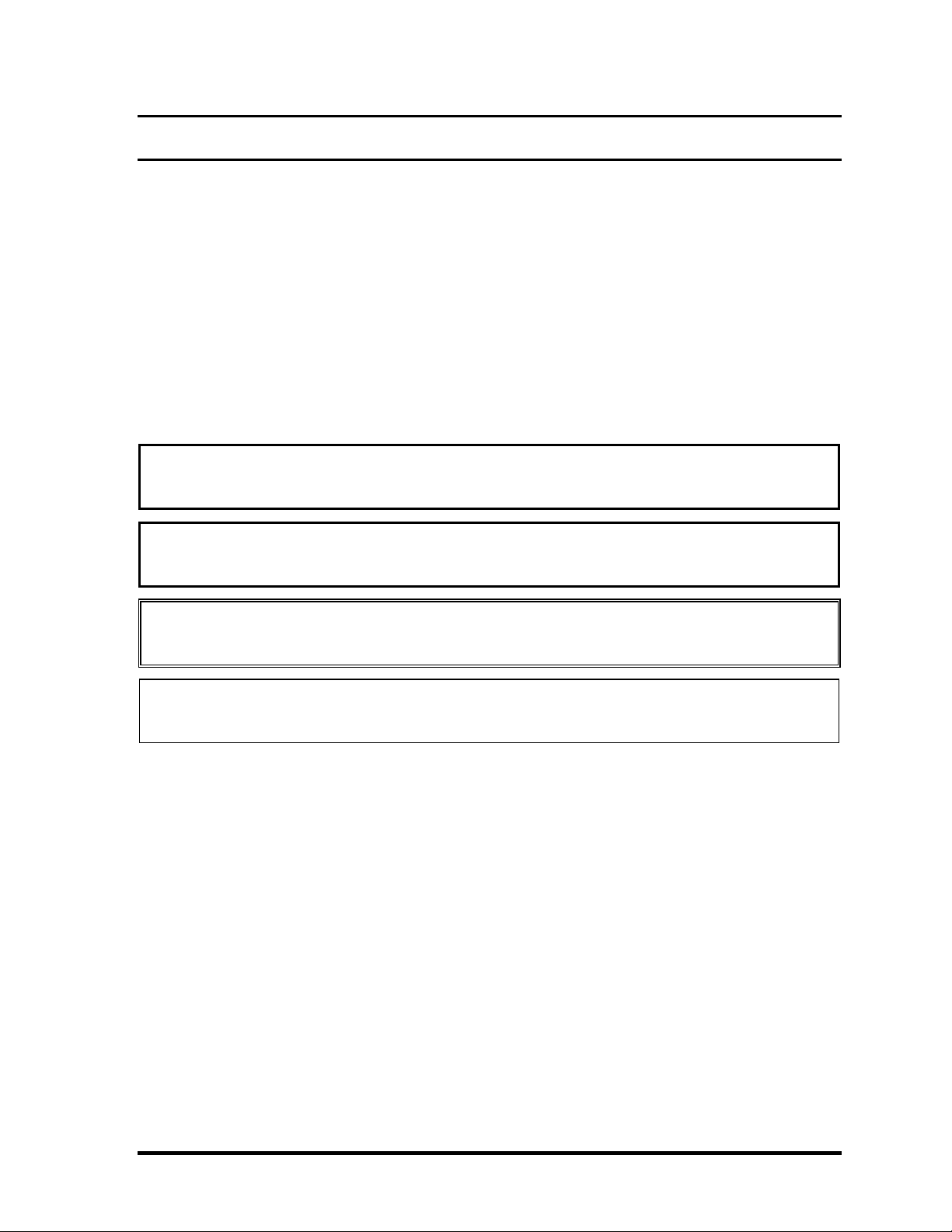
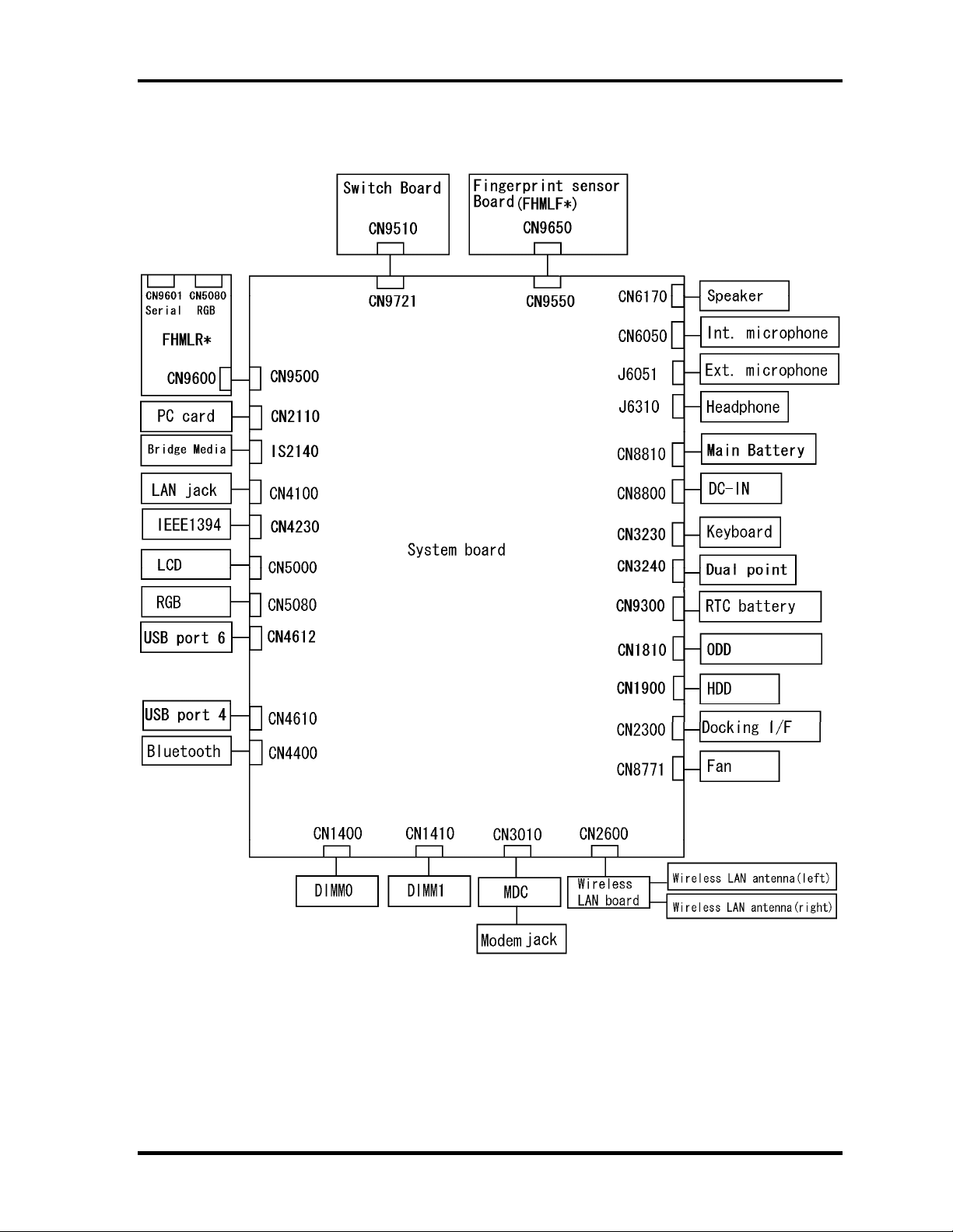
1.2 System Unit Block Diagram
Figure 1-3 is a block diagram of the system unit.
Figure 1-3 System unit block diagram
1-8 [CONFIDENTIAL] TECRA A9(S5/P5/S200) Maintenance Manual (960-633)

1.2 System Unit Block Diagram 1 Hardware Overview
The system unit is composed of the following major components:
Processor
• Intel
®
CoreTM 2 Duo Processor
• Core speed:
• • 2.40GHz (T7700) /2.20GHz (T7500) / 2.00GHz (T7300)
In the case of Processor which built in 4MB L2 cache memory
1.80GHz (T7100)
In the case of Processor which built in 2MB L2 cache memory
( ): Processor Number
– Processor bus speed: 800MHz
– Core voltage: 0.50V to 1.325V
– Integrated L2 cache memory of 2MB or 4MB
– Integrated NDP
– 478-pin Micro FC-PGA package
Memory
Two memory slots are provided. Expansion up to 4GB (4,096MB) is available.
Memory
• DDR2-SDRAM
• 667MHz
• 1.8 volt operation
• FBGA
Memory Module
• 200 pin, SO Dual In-line Memory Module (SO-DIMM)
• PC 5300
• 512MB/1GB (1,024MB)/2GB (2,048MB)
TECRA A9(S5/P5/S200) Maintenance Manual (960-633)[CONFIDENTIAL] 1-9

1 Hardware Overview 1.2 System Unit Block Diagram
Intel 965GM/GML (Crestline-GM (North Bridge))
• Features:
– Meorom Processor System Bus Supports
– PCI Express Based Graphics Interface
– System Memory supports :DDR2-533/DDR2-667, 4GB max.
– DMI(Direct Media Interface)
– Power management control (ACPI2.0 conformity)
Intel ICH8M (South Bridge)
• Features:
– DMI(Direct Media Interface)
– PCI Express Interface
– PCI Bus I/F Rev2.3(4 PCI REQ/GNT Pairs)
– Integrated Serial ATA Host Controller
– Integrated IDE Controller(Ultra ATA 100/66/33)
– Intel High Definition controller (Azalia)
– USB 1.1/2.0 Controller
– Power Management (ACPI 2.0 compliance)
– SMBus2.0 controller
– SPI Interface(BIOS)
– LPC interface (EC/KBC, Super I/O)
– IRQ controller
– Serial Interrupt Function
– Suspend/Resume control
– Built –in RTC
– GPIO
1-10 [CONFIDENTIAL] TECRA A9(S5/P5/S200) Maintenance Manual (960-633)

1.2 System Unit Block Diagram 1 Hardware Overview
Cardbus controller (TI PCI8412ZHK)
− PCI Interface(PCI Rev.2.2)
− SD IO Controller(Ver.1.1)
− CardBus / Ultra media Controller (Yenta Ver.2.2:1 socket)
− SD/MMC(SDHC Ver. 1.2 revised edition) , Memory Stick, Memory Stick
pro, XD Card Controller
− 1394 Controller
− 16 x16x1.4mm BGA Package
VGA
As for a TECRA A9 or Satellite Pro S200 , the internal graphics controller in North
Bridge is used.(PTS52*)
As for a TECRA S5, the graphics controller is nVIDIA G8M-SE or GS.(PTS53*)
Sound Controller
• Azalia
• Amplifier: Mathushita made AN12941A
• Stereo speakers
• Digital volume control
• Supports VoIP
• Stereo headphone jack
• External microphone jack
• Built-in microphone
EC/KBC (Embedded Controller/Keyboard Controller)
• One Mitsubishi M306KAFCLPR micon chip functions as both EC and KBC.
TECRA A9(S5/P5/S200) Maintenance Manual (960-633)[CONFIDENTIAL] 1-11

1 Hardware Overview 1.2 System Unit Block Diagram
PSC (Power Supply Controller)
• One TMP86FS49AUG chip is used.
• This controller controls the power sources.
Clock Generator
• IDT 9LPR501PGLFT is used.
• This device generates the system clock.
Modem Controller
• One MDC is used.
• This controller has the following functions:
– One RJ11 port
– Azalia MDC1.5
– V.92 (V.90) 56K Modem/FAX
– Ring wake up support
Internal LAN Controller
• Intel made only GigaBit Ether is used.
• This controller has the following functions:
– PCI-Ex connection
– Supports Gigabit Ethernet
– One RJ45 port
– WOL support
– Magic Packet support
– LED support
1-12 [CONFIDENTIAL] TECRA A9(S5/P5/S200) Maintenance Manual (960-633)

1.2 System Unit Block Diagram 1 Hardware Overview
Wireless LAN
• One PCI-Ex MiniCard
• Intel Kedron a/b/g or a/b/g/n
• Supports Wireless Communication SW
• Supports W-LAN via PCMCIA (Euro : GSM/GPRS)
Super I/O
• SMSC LPC47N217-JV chip is used.
• This gate array has the following features:
– Serial Port Controller
– GPIO Controller
Bluetooth
• V2.0+EDR
• USB interface connection
Sensor
• Thermal Sensor: One ADM1032ARMZ chip is used.
• LCD Sensor: One NRS-701-1015T chip is used.
• Acceleration Sensor
TECRA A9(S5/P5/S200) Maintenance Manual (960-633)[CONFIDENTIAL] 1-13

1 Hardware Overview 1.3 3.5-inch Floppy Disk Drive (USB External)
1.3 3.5-inch Floppy Disk Drive (USB External)
The 3.5-inch FDD is a thin, high-performance reliable drive that supports 720KB (formatted)
2DD and 1.44MB (formatted) 2HD disks.
The FDD is shown in figure 1-4. The specifications for the FDD are listed in Table 1-1.
Figure 1-4 3.5-inch FDD (USB External)
Table 1-1 3.5-inch FDD specifications
TEAC FD-05PUB-337
Items
720KB mode 1.44MB mode
FDD part 250K bits/second 500K bits/second Data transfer rate
USB Full speed mode (12M bits/second)
Disk rotation speed 300rpm
Track density 5.3 track/mm (135TPI)
(G8AC0000B320)
1-14 [CONFIDENTIAL] TECRA A9(S5/P5/S200) Maintenance Manual (960-633)
1.4 2.5-inch Hard Disk Drive 1 Hardware Overview
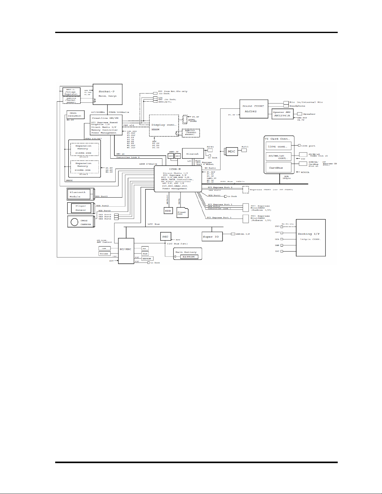
1.4 2.5-inch Hard Disk Drive
The removable HDD is a random access non-volatile storage device. It has a non-removable
2.5-inch magnetic disk and mini-Winchester type magnetic heads.
The computer supports a 80GB, 120GB or 160GB.
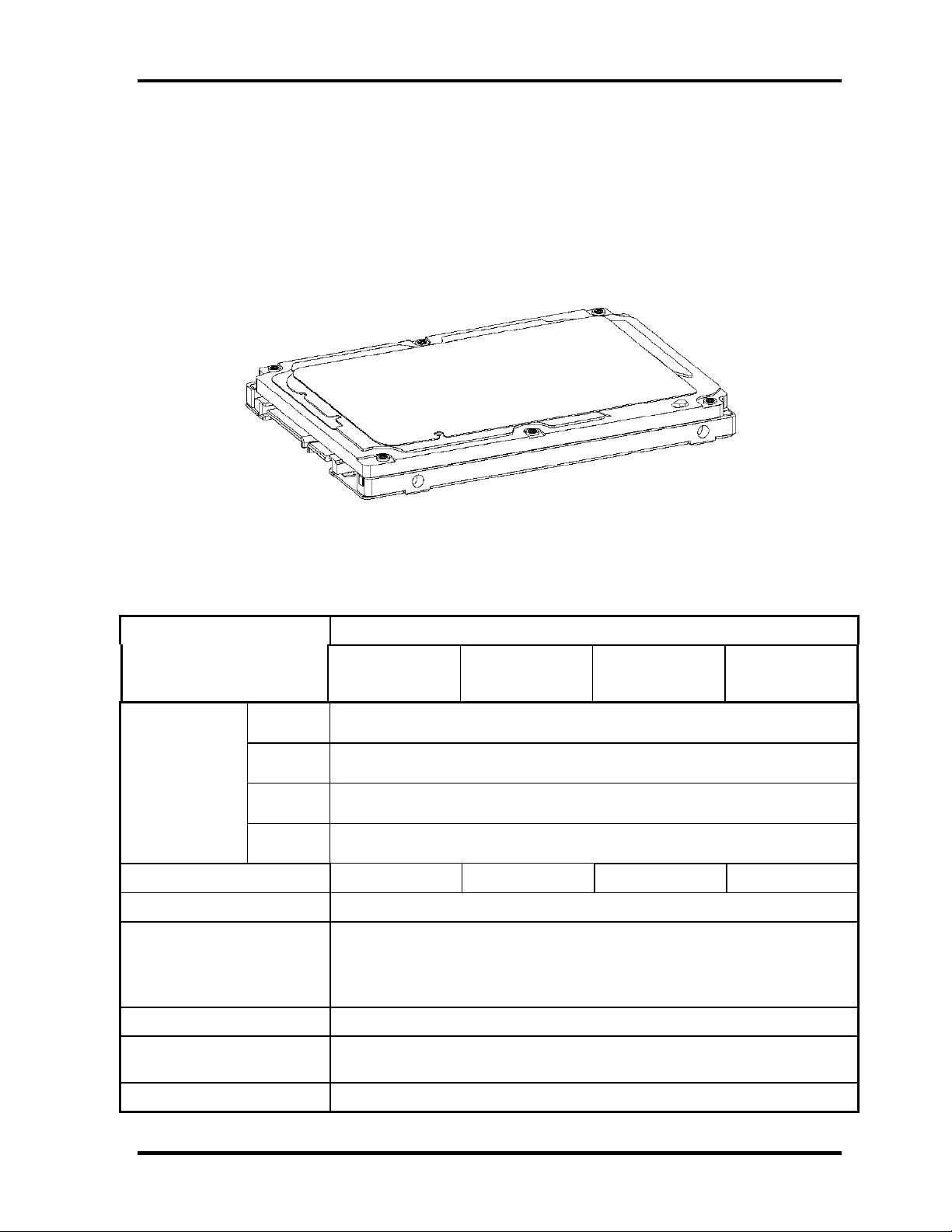
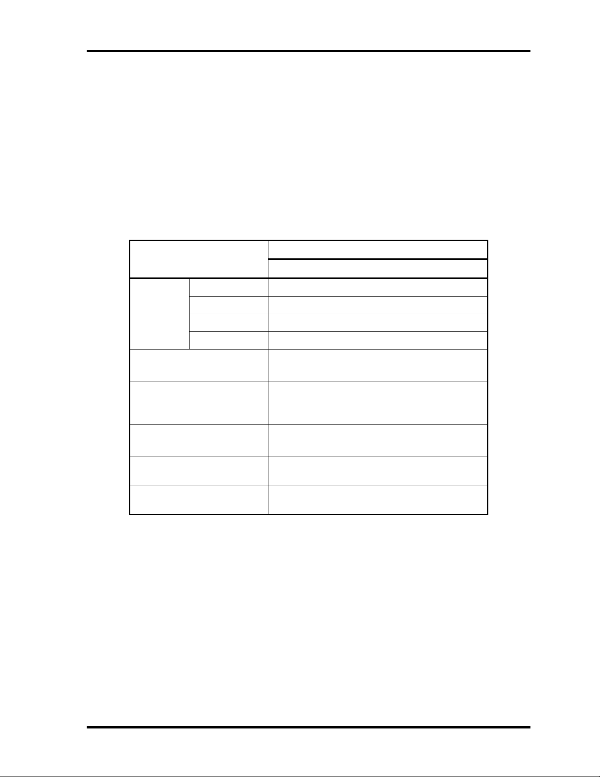
The HDD is shown in figure 1-5. Specifications are listed in Table 1-2.
Figure 1-5 2.5-inch HDD
Table 1-2 2.5-inch HDD specifications
Items Specifications
Outline Width
(mm)
Dimensions Height
(mm)
Depth
(mm)
Weight
(g)
Storage size (formatted) 60GB 80GB 120GB 160GB
Speed (RPM) 5,400
Data transfer speed (Mb/s)
To/Form Media
To/Form Host
FUJITSU
G8BC0003H060
FUJITSU
G8BC0003J080
101 max
72.4 MB/s Max
150 MB/s (Genli)
FUJITSU
G8BC0003H120
100.0
9.5
70.0
FUJITSU
G8BC0003J160
Data buffer size (MB/s) 8
Positioning Time(read and
seek time)
Motor startup time (s) 4
Read: 12ms
TECRA A9(S5/P5/S200) Maintenance Manual (960-633)[CONFIDENTIAL] 1-15
1 Hardware Overview 1.5 Optical Drive (ODD)
1.5 Optical Drive (ODD)
1.5.1 CD-ROM Drive
The CD-ROM drive accommodates either 12 cm (4.72-inch) or 8 cm (3.15-inch) CD-ROM.
The specifications of the CD-ROM are described in Table 1-2.
Table 1-2 CD-ROM drive specifications
Item
Outline
dimensions
Data transfer speed (Read)
CD-ROM
ATAPI Burst (MB/s)
Burst
Sustained
Access time (ms)
CD-ROM
Supported Disks CD: CD/CD-ROM (12cm, 8cm), CD-R,
Supported Formats CD: CD-DA, CD-ROM, CD-ROM XA,
Width (mm) 128 (excluding projections)
Height (mm) 12.7(excluding projections)
Depth (mm) 129.4 (excluding projections)
Mass (g) 165 or less
CD-RW
PHOTO CD, Enhanced CD
Specifications
TEAC G8CC00039520
Max. 24x CAV
33.3Mbytes/sec max.
1,545 -3,600kB/sec
110 typ.
1-16 [CONFIDENTIAL] TECRA A9(S5/P5/S200) Maintenance Manual (960-633)
Loading...