


satellite m500
Table of contents
 Loading...
[CONFIDENTIAL]
Toshiba Personal Computer
Satellite M500/M505/M507
Maintenance Manual
TOSHIBA CORPORATION
File Number

ii [CONFIDENTIAL] Satellite M500/M505/M507 Maintenance Manual
Copyright
© 2007 by Toshiba Corporation. All rights reserved. Under the copyright laws, this manual
cannot be reproduced in any form without the prior written permission of Toshiba. No patent
liability is assumed with respect to the use of the information contained herein.
Toshiba Personal Computer Satellite M500/M505/M507 Maintenance Manual
First edition June 2009
Disclaimer
The information presented in this manual has been reviewed and validated for accuracy. The
included set of instructions and descriptions are accurate for the Satellite M500/M505/M507
at the time of this manual's production. However, succeeding computers and manuals are
subject to change without notice. Therefore, Toshiba assumes no liability for damages
incurred directly or indirectly from errors, omissions, or discrepancies between any
succeeding product and this manual.
Trademarks
IBM is a registered trademark and IBM PC is a trademark of International Business
Machines Corporation.
Intel, Intel SpeedStep, Intel Core and Centrino are trademarks or registered trademarks of
Intel Corporation or its subsidiaries in the United States and other countries/regions.
Windows and Microsoft are registered trademarks of Microsoft Corporation.
Photo CD is a trademark of Eastman Kodak.
Sonic RecordNow! is a registered trademark of Sonic Solutions.
Bluetooth is a trademark owned by its proprietor and used by TOSHIBA under license.
i.LINK is trademark and registered trademark of Sony Corporation.
InterVideo and WinDVD are registered trademarks of InterVideo Inc. WinDVD Creator is
trademark of InterVideo Inc.
Other trademarks and registered trademarks not listed above may be used in this manual.
Satellite M500/M505/M507 Maintenance Manual [CONFIDENTIAL] iii
Preface
This maintenance manual describes how to perform hardware service maintenance for the
Toshiba Personal Computer Satellite M500/M505/M507.
The procedures described in this manual are intended to help service technicians isolate
faulty Field Replaceable Units (FRUs) and replace them in the field.
SAFETY PRECAUTIONS
Four types of m
essages are used in this manual to bring important information to your
attention. Each of these messages will be italicized and identified as shown below.
DANGER: “Danger” indicates the existence of a hazard that could result in death or
serious bodily injury, if the safety instruction is not observed.
WARNING: “Warning” indicates the existence of a hazard that could result in bodily
injury, if the safety instruction is not observed.
CAUTION: “Caution” indicates the existence of a hazard that could result in property
damage, if the safety instruction is not observed.
NOTE: “Note” contains general information that relates to your safe maintenance
service.
Improper repair of the computer may result in safety hazards. Toshiba requires service
technicians and authorized dealers or service providers to ensure the following safety
precautions are adhered to strictly.
Be sure to fasten screws securely with the right screwdriver. If a screw is not fully
fastened, it could come loose, creating a danger of a short circuit, which could cause
overheating, smoke or fire.
If you replace the battery pack or RTC battery, be sure to use only the same model
battery or an equivalent battery recommended by Toshiba. Installation of the wrong
battery can cause the battery to explode.

iv [CONFIDENTIAL] Satellite M500/M505/M507 Maintenance Manual
The manual is divided into the following parts:
Chapter 1 Hardware Overview describes the Satellite M500/M505/M507 system
unit and each FRU.
Chapter 2 Troubleshooting Procedures explains how to diagnose and resolve
FRU problems.
Chapter 3 Test and Diagnostics describes how to perform test and diagnostic
operations for maintenance service.
Chapter 4 Replacement Procedures describes the removal and replacement of the
FRUs.
Appendices The appendices describe the following:
Handling the LCD module
Board layout
Pin assignments
Keyboard scan/character codes
Key layout
BIOS rewrite procedures
EC/KBC rewrite procedures

Satellite M500/M505/M507 Maintenance Manual [CONFIDENTIAL] v
Conventions
This manual uses the following formats to describe, identify, and highlight terms and
operating procedures.
Acronyms
On the first appearance and whenever necessary for clarification acronyms are enclosed in
parentheses following their definition. For example:
Read Only Memory (ROM)
Keys
Keys are used in the text to describe m
any operations. The key top symbol as it appears on
the keyboard is printed in boldface type.
Key operation
Som
e operations require you to simultaneously use two or more keys. We identify such
operations by the key top symbols separated by a plus (+) sign. For example, Ctrl + Pause
(Break) means you must hold down Ctrl and at the same time press Pause (Break). If
three keys are used, hold down the first two and at the same time press the third.
User input
Text that you are instructed to type in is shown in the boldface type below:
DISKCOPY A: B:
The display
Text generated by the com
puter that appears on its display is presented in the type face
below:
Format complete
System transferred

vi [CONFIDENTIAL] Satellite M500/M505/M507 Maintenance Manual
Table of Contents
Chapter 1 Hardware Overview
1.1
Features.................................................................... 1-Error! Bookmark not defined.
1.2 System Unit Block Diagram.................................... 1-Error! Bookmark not defined.
1.3 HDD/SSD ................................................................ 1-Error! Bookmark not defined.
1.4 DVD Super Multi Drive........................................... 1-Error! Bookmark not defined.
1.5 Keyboard..................................................................1-Error! Bookmark not defined.
1.6 TFT Color Display...................................................1-Error! Bookmark not defined.
1.7 Power Supply........................................................... 1-Error! Bookmark not defined.
1.8 Batteries ................................................................... 1-Error! Bookmark not defined.
1.9 AC Adaptor.............................................................. 1-Error! Bookmark not defined.
Chapter 2 Troubleshooting Procedures
Troubleshooting Procedures ........................................... 2-Error! Bookmark not defined.
2.1 Troubleshooting....................................................... 2-Error! Bookmark not defined.
2.2 Troubleshooting Flowchart...................................... 2-Error! Bookmark not defined.
2.3 Power Supply Troubleshooting................................ 2-Error! Bookmark not defined.
2.4 Main Board Troubleshooting................................... 2-Error! Bookmark not defined.
2.5 HDD/SSD Troubleshooting..................................... 2-Error! Bookmark not defined.
2.6 Keyboard and Touch pad Troubleshooting.............. 2-Error! Bookmark not defined.
2.7 Display Troubleshooting.......................................... 2-Error! Bookmark not defined.
2.8 Optical Drive Troubleshooting................................2-Error! Bookmark not defined.
2.9 Modem Troubleshooting.......................................... 2-Error! Bookmark not defined.
2.10 LAN Troubleshooting.............................................. 2-Error! Bookmark not defined.
2.11 Wireless LAN Troubleshooting............................... 2-Error! Bookmark not defined.
2.12 Sound Troubleshooting............................................ 2-Error! Bookmark not defined.
2.13 Card Reader Slot Troubleshooting .......................... 2-Error! Bookmark not defined.
2.14 PCI Express Card Slot Troubleshooting.................. 2-Error! Bookmark not defined.
2.15 Fingerprint Board(BTO) Troubleshooting............... 2-Error! Bookmark not defined.

Satellite M500/M505/M507 Maintenance Manual [CONFIDENTIAL] vii
2.16 Bluetooth(BTO) Troubleshooting............................ 2-Error! Bookmark not defined.
2.17 3G(BTO) Troubleshooting....................................... 2-Error! Bookmark not defined.
2.18 Camera(BTO) Troubleshooting............................... 2-Error! Bookmark not defined.
Chapter 3 Tests and Diagnostics
Tests and Diagnostics .......................................................... 3-Error! Bookmark not defined.
3.1 Model,BIOS and CPU Test...................................... 3-Error! Bookmark not defined.
3.1.1 CPU Test.................................................................. 3-Error! Bookmark not defined.
3.1.2 Memory Test............................................................ 3-Error! Bookmark not defined.
3.2 Check MAC Test ..................................................... 3-Error! Bookmark not defined.
3.3 ACIN Test................................................................ 3-Error! Bookmark not defined.
3.4 Temperature Test..................................................... 3-Error! Bookmark not defined.
3.5 USB TEST ............................................................... 3-Error! Bookmark not defined.
3.6 USBCCD Test.......................................................... 3-Error! Bookmark not defined.
3.7 PAD Test.................................................................. 3-Error! Bookmark not defined.
3.8 LCDRGB Test ......................................................... 3-Error! Bookmark not defined.
3.9 VGA Test................................................................. 3-Error! Bookmark not defined.
3.10 Audio Test................................................................ 3-Error! Bookmark not defined.
3.11 Keyboard Test.......................................................... 3-Error! Bookmark not defined.
3.12 Function TEST......................................................... 3-Error! Bookmark not defined.
3.13 LEDALL Test.......................................................... 3-Error! Bookmark not defined.
3.14 STORE Test [CD/DVD-ROM TEST]..................... 3-Error! Bookmark not defined.
3.15 LID Switch Test....................................................... 3-Error! Bookmark not defined.
3.16 MS CARD Test........................................................ 3-Error! Bookmark not defined.
3.17 SD CARD Test ........................................................ 3-Error! Bookmark not defined.
3.18 HDD Test................................................................. 3-Error! Bookmark not defined.
3.19 BATTERY Test ....................................................... 3-Error! Bookmark not defined.
3.20 Touch LED Test....................................................... 3-Error! Bookmark not defined.
3.21 HDD 3D Protection.................................................. 3-Error! Bookmark not defined.
3.22 Speaker Test............................................................. 3-Error! Bookmark not defined.
3.23 Auto Run.................................................................. 3-Error! Bookmark not defined.
3.0 Appendix:................................................................. 3-Error! Bookmark not defined.

viii [CONFIDENTIAL] Satellite M500/M505/M507 Maintenance Manual
Chapter 4 Replacement Procedures
4.1 General...................................................................Error! Bookmark not defined.
4.2 Battery pack...........................................................Error! Bookmark not defined.
4.3 Express card...........................................................Error! Bookmark not defined.
4.4 HDD module..........................................................Error! Bookmark not defined.
4.5 Memory module.....................................................Error! Bookmark not defined.
4.6 Wireless LAN card ................................................Error! Bookmark not defined.
4.7 Keyboard................................................................Error! Bookmark not defined.
4.8 Top cover...............................................................Error! Bookmark not defined.
4.9 Bluetooth................................................................Error! Bookmark not defined.
4.10 Power Button Board...............................................Error! Bookmark not defined.
4.11 Fingerprint module.................................................Error! Bookmark not defined.
4.12 Touchpad on-off board ..........................................Error! Bookmark not defined.
4.13 Main PCB...............................................................Error! Bookmark not defined.
4.14 LAN Board.............................................................Error! Bookmark not defined.
4.15 D/C IN Cable .........................................................Error! Bookmark not defined.
4.16 Speaker...................................................................Error! Bookmark not defined.
4.17 Remove LCD Module............................................Error! Bookmark not defined.
4.18 CPU Heat sink/CPU...............................................Error! Bookmark not defined.
4.19 VGA Card..............................................................Error! Bookmark not defined.
4.20 FAN Error! Bookmark not defined.
4.21 LCD unit/Camera...................................................Error! Bookmark not defined.

Satellite M500/M505/M507 Maintenance Manual [CONFIDENTIAL] ix
Appendices
Appendix A Handling the LCD Module ........................................................................... A-1
Appendix B Board Layout ................................................................................................ B-1
Appendix C Pin Assignments............................................................................................ C-1
Appendix D Keyboard Scan/Character Codes .................................................................. D-1
Appendix E Key Layout.....................................................................................................E-1
Appendix F BIOS rewrite Procedures...............................................................................F-1
Appendix G EC/KBC rewrite Procedures.........................................................................G-1

1 Hardware Overview
Satellite M500/M505/M507 Maintenance Manual [CONFIDENTIAL] 1-1
Chapter 1
Hardware Overview

1 Hardware Overview
1-2 [CONFIDENTIAL] Satellite M500/M505/M507 Maintenance Manual
Chapter 1 Contents
1.1 ......................................................................................................................1-4 Features
1.2
....................................................................................1-10 System Unit Block Diagram
1.3
................................................................................................................1-15 HDD/SSD
1.3.1
...................................................................1-15 2.5-inch Hard Disk Drive
1.3.2
.....................................................................................................1-16 SSD
1.4
..........................................................................................1-17 DVD Super Multi Drive
1.5
..................................................................................................................1-19 Keyboard
1.6
...................................................................................................1-20 TFT Color Display
1.7
...........................................................................................................1-21 Power Supply
1.8
...................................................................................................................1-22 Batteries
1.8.1
.......................................................................................1-22 Main Battery
1.8.2
...................................................................1-23 Battery Charging Control
1.8.3
........................................................................................1-23 RTC battery
1.9
..............................................................................................................1-25 AC Adaptor

1 Hardware Overview
Satellite M500/M505/M507 Maintenance Manual [CONFIDENTIAL] 1-3
Figures
Figure 1-1 The front and left view of the computer ............................................................1-8
Figure 1-2 System unit configuration..................................................................................1-9
Figure 1-3 System unit block diagram...............................................................................1-10
Figure 1-4 2.5-inch HDD...................................................................................................1-15
Figure 1-5 SSD ..................................................................................................................1-16
Figure 1-6 DVD Super Multi Drive...................................................................................1-17
Figure 1-7 Keyboard..........................................................................................................1-19
Tables
Table 1-1 2.5-inch HDD specifications (1/1).....................................................................1-15
Table 1-2 1.8-inch SSD specifications (1/1).......................................................................1-16
Table 1-3 DVD Super Multi drive specifications (1/1).....................................................1-18
Table 1-4 LCD module specifications (1/1)......................................................................1-20
Table 1-5 Power supply output rating................................................................................1-21
Table 1-6 Battery specifications........................................................................................1-22
Table 1-7 Time required for charges .................................................................................1-23
Table 1-8 RTC battery charging/data preservation time ...................................................1-24
Table 1-9 AC adaptor specifications for integrated graphic model...................................1-25
Table 1-10 AC adaptor specifications for discrete graphic model...................................... 1-25

1 Hardware Overview
1-4 [CONFIDENTIAL] Satellite M500/M505/M507 Maintenance Manual
1.1 Features
The Toshiba Satellite M500/M505/M507 Personal Computer uses extensive Large Scale
Integration (LSI), and Complementary Metal-Oxide Semiconductor (CMOS) technology
extensively to provide compact size, minimum weight, low power usage and high reliability.
This computer incorporates the following features.
Refer to the Parts List for the configuration of each model and the available options.
Microprocessor
The Satellite M500/M505/M507 computer is equipped with an Intel
®
Core2 Duo
Processor, Intel® Pentium® Dual-Core mobile processor or Intel
®
Celeron Processor.
These processors incorporate a math co-processor with L2 cache memory.
Chipset
The Satellite M500/M505/M507 is equipped with Mobile Intel 4 Series Express Chipset
Family and Intel ICH9-M.
GPU (Graphics Processing Unit)
(1) Integrated graphic model: Intel integrated graphics (Mobile Intel 4 Series Express
Chipset Family)
(2) Discrete graphic model: AMD M92XT
Memory
The computer comes with two DDR2 SO-DIMM slots. Two memory modules of 1GB
(1,024MB), 2GB (2,048MB) or 4GB (4,096MB) can be installed, and it can incorporate
up to 8GB of main memory.
HDD/SSD
(1) HDD: The computer has a 2.5-inch SATA HDD. The following capacities are
available:
160/250/320/400/500 GB
(2) SSD (BTO): The computer has a SSD port with SATA interface supporting
TOSHIBA module type SSD.
Optical Drive
The computer accommodates a fixed 12.7mm ODD with one of following types:
Comment [z1]:
Please add below item.
1.eSATA/USB combo port
2.webcam (BTO)
3.SIM card Slot
4.HDMI
5.Headphone/s/PDIF jack
6. Microphone jack
7.Bluetooth (BTO)
8. Fingerprint (BTO)
9. IEEE 1394 port
Comment [z2]:
Please add AMD M92XT
information.
Comment [z3]:
Please add the below sentence
“It can incorporate up to 8GB of
main memory.”
Comment [z4]:
Please add SSD information.
Comment [z5]:
1. Please add more detail on ODD.
Ex : 12.7mm heigh DVD superMulti
driver support +- R double layer
2. Please add slot in ODD
information.

1 Hardware Overview
Satellite M500/M505/M507 Maintenance Manual [CONFIDENTIAL] 1-5
Tray Type DVD Super Multi +-R Double Layer drive
Tray Type DVD Super Multi +-R Double Layer with Label Flash™ drive
Slot Loading Type DVD Super Multi +-R Double Layer drive
Slot Loading Type DVD Super Multi +-R Double Layer with Label Flash™ drive
Display
The PC comes with 14.0W WXGA (1366*768) CSV LED backlight.
Keyboard
A4 size 86 key (US) and 87 key (UK) keyboard provides a numeric keypad overlay for
fast numeric data entry or for cursor and page control. The keyboard also includes two
keys that have special functions in Microsoft
®
Windows
®
Vista.
Pointing Device
The touch pad and control buttons enable control of the on-screen pointer and scrolling of
windows.
Batteries
The computer has two batteries: a rechargeable Lithium-Ion main battery pack and RTC
battery (that backs up the Real Time Clock and CMOS memory). The capacity of the
main battery pack can be either 6-cell or 12-cell depending on the model of computer.
Universal Serial Bus (USB2.0)
Three USB ports are provided. The ports comply with the USB2.0 standard, which
enables data transfer speeds 40 times faster than USB1.1 standard. USB1.1 is also
supported.
External monitor (RGB) port
The port enables connection of an external monitor, which is recognized automatically by
Video Electronics Standards Association (VESA) Display Data Channel (DDC)
compatible functions.
Express Card slot
An Express Card slot is provided, and accommodates an Express Card. Support the
standard 34mm wide module (ExpressCard / 34) and the standard 54mm wide module
(ExpressCard / 54).
Comment [z6]:
Modify sentence to
“The touch pad and control buttons
enable control of the on-screen
pointer and scrolling of windows.”
Comment [z7]:
Please add below sentence.
“The capacity can be either 6 cell or
12 cell depending on the model of
computer.”
Comment [z8]:
Please add type of Express Card
( 134 and 154 module)

1 Hardware Overview
1-6 [CONFIDENTIAL] Satellite M500/M505/M507 Maintenance Manual
Media Card slot
The Media Card Slot can accommodate all types of media (SD/Mini SD (card adapter is
needed)/Micro SD (card adapter is needed)/SDHC memory card/MMC/Memory
stick/Memory stick PRO/memory stick pro duo (card adapter is needed)/XD) with
various capacities. Media cards let you easily transfer data from devices, such as digital
cameras and Personal Digital Assistants, which use Media Card flash-memory.
Sound system
The sound system is equipped with the following features:
Azalia Link (Intel High Definition Audio I/F) built in the Intel ICH9-M + Realtek
ALC269
Amplifier: Realtek ALC269 built-in
Speaker: Non-brand or Harman/Kardon speaker (depending on model)
Internal modem
The computer contains an MDC, enabling data and fax communication. The transfer rates
are 56 Kbps for data reception. The actual speed depends on the line quality. The RJ11
modem jack is used to accommodate a telephone line.
Internal LAN (BTO)
The computer is equipped with LAN circuits that support Ethernet LAN (10/100 Mbps or
10/100/1000 Mbps). It also supports Wakeup on LAN (WOL), Magic Packet and LED.
Wireless LAN
The computer is equipped with PCI-E MiniCard type wireless LAN board that supports
802.11 a/b/g in the PCI-E MiniCard slot. This function can be switched on and off by a
switch on the computer.
eSATA / USB Combo port
The computer is equipped with an eSATA and USB combo port that supports connection
of an external eSATA or USB device.
The USB port complies with the USB 2.0 standard, which enables data transfer speeds 40
times faster than USB1.1 standard. USB1.1 is also supported, and also supports Sleep and
Charge function that can supply bus power to USB when the PC is sleeping.
Comment [z9]:
Please input all types (SD/Mini
SD/Micro SD/SDHC memory
card/MMC/Memory stick/Memory
stick PRO/memory stick pro duo/XD
)
Comment [z10]:
Please add Harman/kardon
(Depending on model) information.

1 Hardware Overview
Satellite M500/M505/M507 Maintenance Manual [CONFIDENTIAL] 1-7
Webcam Module (BTO)
The computer is equipped with a webcam module which is embedded to transfer video
data – to take still image and offer video stream for end user to preview/record motion
image through USB 2.0 interface.
SIM card slot
A user accessible SIM card slot is provided behind battery.
HDMI port
A HDMI port is provided which complies with the HDMI 1.3 standard.
Headphone / S/PDIF jack
The computer is equipped with a headphone jack which is shared with S/PDIF jack.
Microphone Jack
The computer is equipped with a microphone jack.
Bluetooth Module (BTO)
The computer is equipped with a Bluetooth module with antenna through USB interface.
Fingerprint (BTO)
The fingerprint sensor can support on-chip fingerprint matching functionality and
security engine.
1 Hardware Overview
1-8 [CONFIDENTIAL] Satellite M500/M505/M507 Maintenance Manual
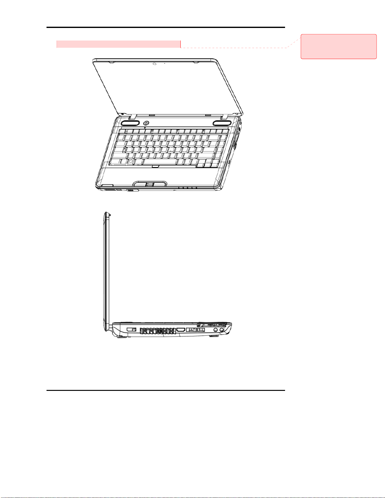
The front of the computer is shown in figure 1-1.
Comment [z11]:
Please use the more detail photo to
show computer and system unit
configuration.
Figure 1-1 The front and left view of the computer
1 Hardware Overview
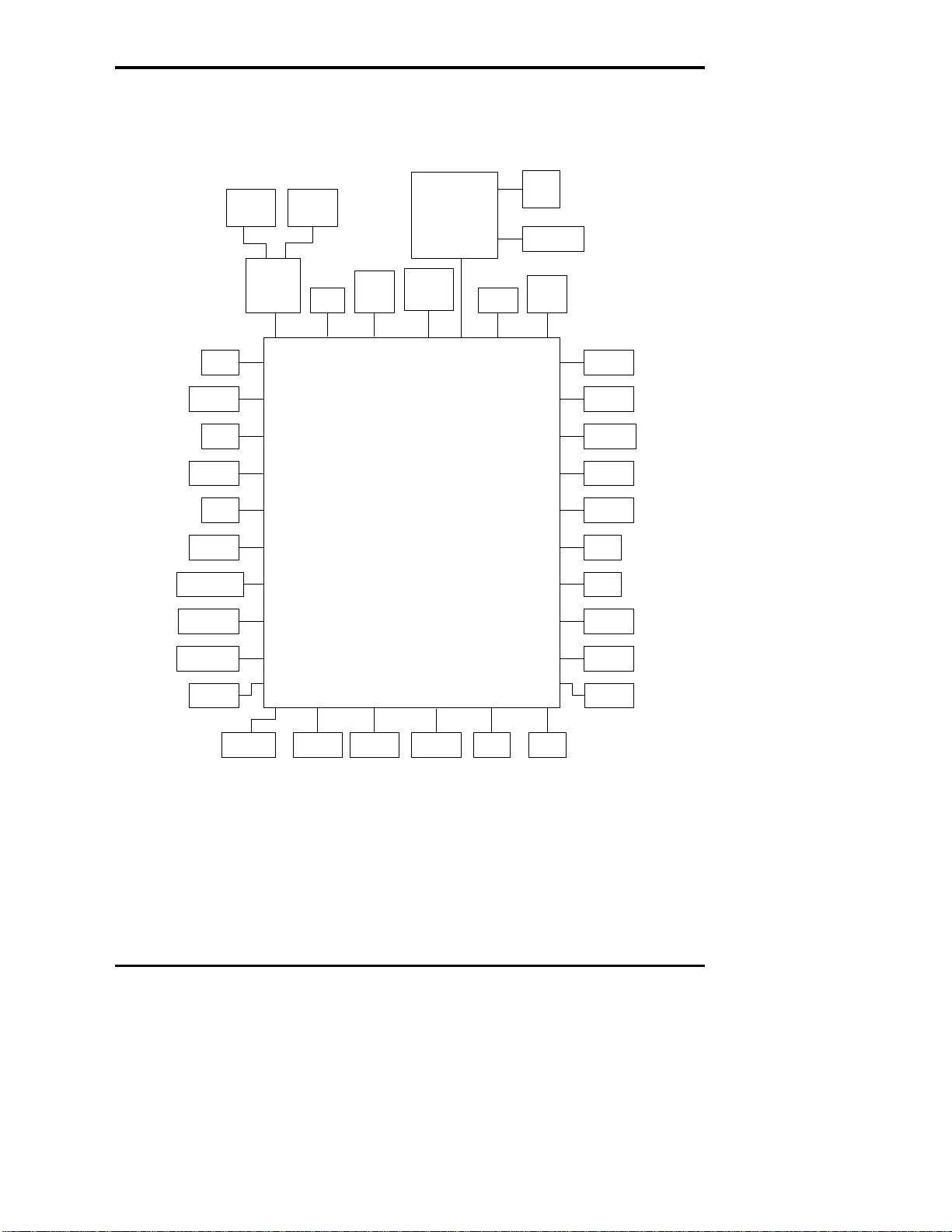
The system unit configuration is shown in figure 1-2.
Main Board
Touch PAD
Board
Touch
PAD
LAN
Board
USB*2
MLCON103
CON6701
LCD
RGB
eSATA/USB
Med
Ca
ia
rd
Newcard
DIMM0 DIMM1 Speaker
SIM
card
DC-IN
Keyboard
USB*1
HDD
HDMI
ODD Battery
CON6002
MIC
HP/
SPDIF
WLAN
CON5701
CON6501
BTO
CON4201
CON4802
CON7701
J7701
CON4801
CON6106
CON6001
CON3901
BTO
CON5602
CON410
1
M1TP_CON1
CON2201
CON2101
CON3801
CON6107
CON5001
CON5401
LAN/RJ11
MLCON301
Fu
B
nction
oard
CON6601
Power
Button
Board
CON6503
BlueToot
h
Camera
CON6203
CON6202
BTO
Touch
Panel
CON6201
BTO
CON3701
Felica
CON6204
BTO
SSD
CON6003
BTO
WWAN
CON5601
BTO
Upconvert
CON5501
BTO
Fingerprint
M1TP_J1
BTO
T/P
ON/OFF
Board
CON4804
MLCON101
CON4901
FAN
MDC
CON4202
Figure 1-2 System unit configuration
Satellite M500/M505/M507 Maintenance Manual [CONFIDENTIAL] 1-9
1 Hardware Overview
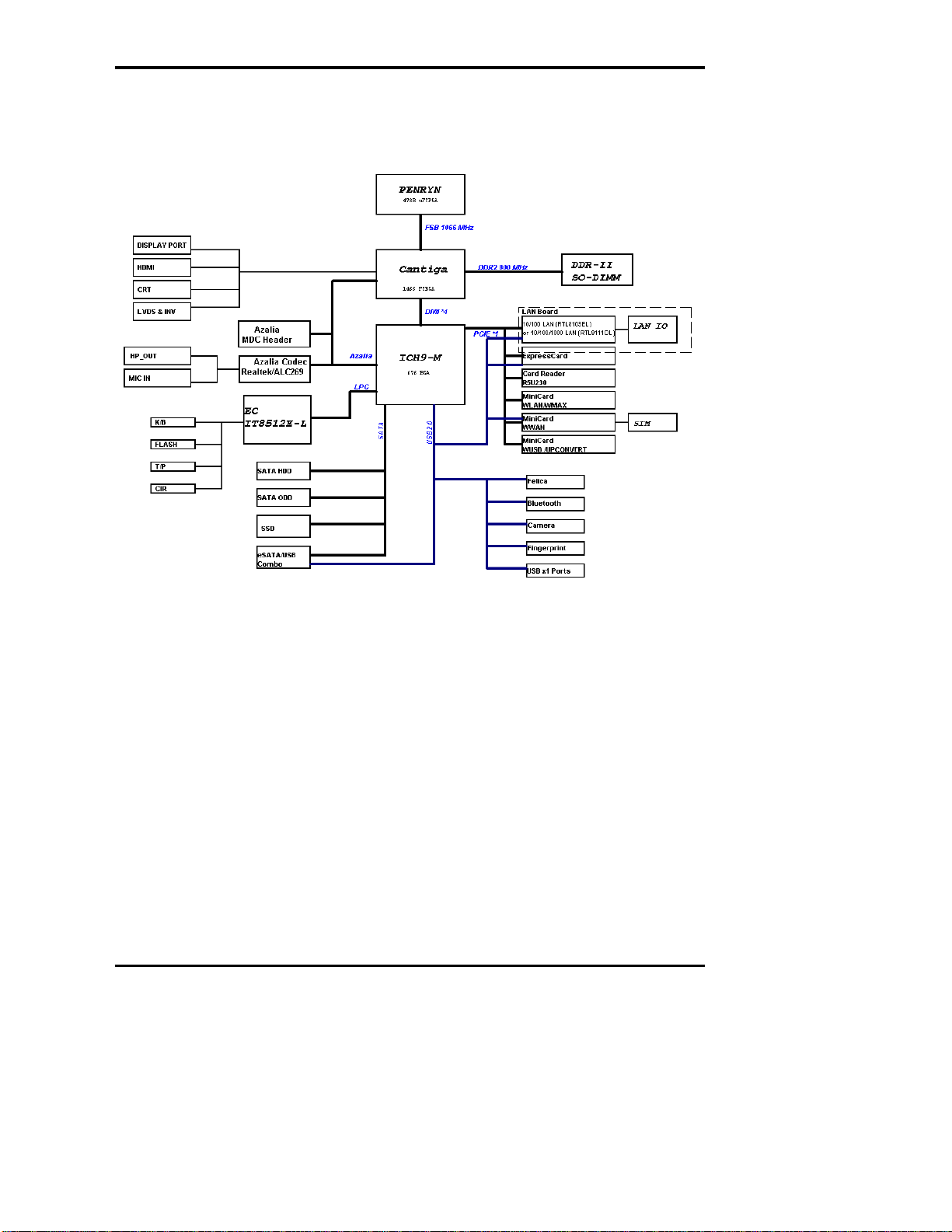
1.2 System Unit Block Diagram
Figure 1-3 is a block diagram of the system unit.
Figure 1-3 System unit block diagram
1-10 [CONFIDENTIAL] Satellite M500/M505/M507 Maintenance Manual

1 Hardware Overview
Satellite M500/M505/M507 Maintenance Manual [CONFIDENTIAL] 1-11
The system unit is composed of the following major components:
Processor
Intel
®
Core2 Duo Processor, Intel® Pentium® Dual-Core mobile processor or
Mobile Intel
®
Celeron Processor
Core speed:
Intel® Core2 Duo mobile processors:
3.06GHz(T9900), 2.8GHz(P9700), 2.8GHz (T9600), 2.66GHz (P8800),
2.53GHz (P8700), 2.26GHz (P7550), 2.2GHz (T6600), 2.1GHz (T6500),
2.0GHz (P7350)
Intel® Pentium® Dual-Core mobile processor:
2.1GHz(T4300), 2.0GHz(T4200), 1.9GHz (T3100), 1.8GHz(T3000)
Mobile Intel® Celeron® Processors: 2.2GHz (900)
478-pin Micro FCPGA package
BIOS EEPROM
8 Mbit SPI serial flash
Supply voltage: 2.7~3.6V
Low power consumption: active read: 10mA (typical); standby: 5uA (typical).
8-lead SOIC package
Memory
Two memory slots are provided. Expansion up to 8GB is available.
Memory
– DDR2-SDRAM
– 800MHz
– 1.8 volt operation
– FBGA
Comment [z12]:
Please add BIOS ROM (Flash EEP
ROM) information.
Comment [z13]:
Please add core speed detail.

1 Hardware Overview
1-12 [CONFIDENTIAL] Satellite M500/M505/M507 Maintenance Manual
Memory Module
– 200 pin, SO Dual In-line Memory Module (SO-DIMM)
– PC6400
– 1GB (1,024MB), 2GB (2,048MB), 4GB (4,096MB)
Intel GMCH (North Bridge)
One Intel® 4 Series Express Chipset is used
Features:
– 667/800/1066 MHz FSB
– Supports DDR2/DDR3
– 8GB maximum memory support
– Internal Graphics Controller: 533MHz core render clock @1.05V core voltage
– DMI: 2GB/s (1GB/s each direction), point-to-point interface to ICH
– 1329-ball 34 mm x 34 mm FCBGA package
Intel ICH9-M (South Bridge)
One Intel ICH9-M is used
Features:
– DMI (Direct Media Interface)
– PCI Express: 6 PCI Express root ports, Supports PCI Express 1.1
– PCI Bus I/F: Supports PCI Rev 2.3 Specification at 33 MHz
– Integrated Serial ATA Host Controller: 6 SATA ports. Data transfer rates up to
3.0Gb/s. Integrated AHCI controller
– External SATA support
– Intel High Definition Audio Interface: Independent Bus Master logic for 8
general purpose streams: 4 input and 4 output
– USB 2.0: 6 UHCI Host Controllers, supporting up to 12 external ports. 2 EHCI
Host Controllers, supporting up to 12 external ports
– Power Management Logic: Supports ACPI 3.0b. Support for “Intel SpeedStep
Technology” processor power control and “Deeper Sleep” power state
– Enhanced DMA Controller
– SMBus controller: Supports SMBus 2.0 Specification
Comment [z14]:
This should be ICH9-M

1 Hardware Overview
Satellite M500/M505/M507 Maintenance Manual [CONFIDENTIAL] 1-13
– Real-Time Clock: 256-byte battery-backed CMOS RAM
– Low Pin Count (LPC) I/F: Supports 2 Master/DMA devices
– GPIO
– 676-ball 31mm×31mm mBGA Package
Card Reader Controller
One Ricoh R5U230 is used
Futures:
– PCI Express I/F
– SD/MMC, Memory Stick, XD Card Controller
– 48-pin, 6mm×6mm, QFN Package
Sound Controller
Realtek ALC269
Mono Microphone-in and stereo headphone-out shared with SPDIF.
Internal Microphone
Volume control: Digital control
Stereo w/box, 4 ohm / 1.5W. L/R = 12.7cc/10.65cc (Harman/Kardon); 13cc/11cc
(Non-brand).
EC/KBC (Embedded Controller/Keyboard Controller)
One ITE8512E chip functions as both EC and KBC.
Clock Generator
One Intel CK-505 compatible clock generator is used.
This device generates the system clocks
Modem Controller

1 Hardware Overview
1-14 [CONFIDENTIAL] Satellite M500/M505/M507 Maintenance Manual
On e MDC is used
This controller has the following functions:
– One RJ11 port
– Digital line protection support
– V.92 (V.90) 56K Modem/FAX
LAN Controller
Realtek RTL8103EL or RTL8111DL is used (depending on model)
This controller has the following functions:
– PCIE I/F
– Supports 10/100 Mbps or 10/100/1000 Mbps Ethernet
– One RJ45 port
– WOL support
– Magic Packet support
Wireless LAN
One PCI-E MiniCard is used
Support 802.11 a/b/g/n or 802.11 a/b/g or 802.11 b/g/n
Sensor
Thermal Sensor: One MAXIM MAX6657 or compatible chip is used
1 Hardware Overview
1.3 HDD/SSD
Satellite M500/M505/M507 Maintenance Manual [CONFIDENTIAL] 1-15
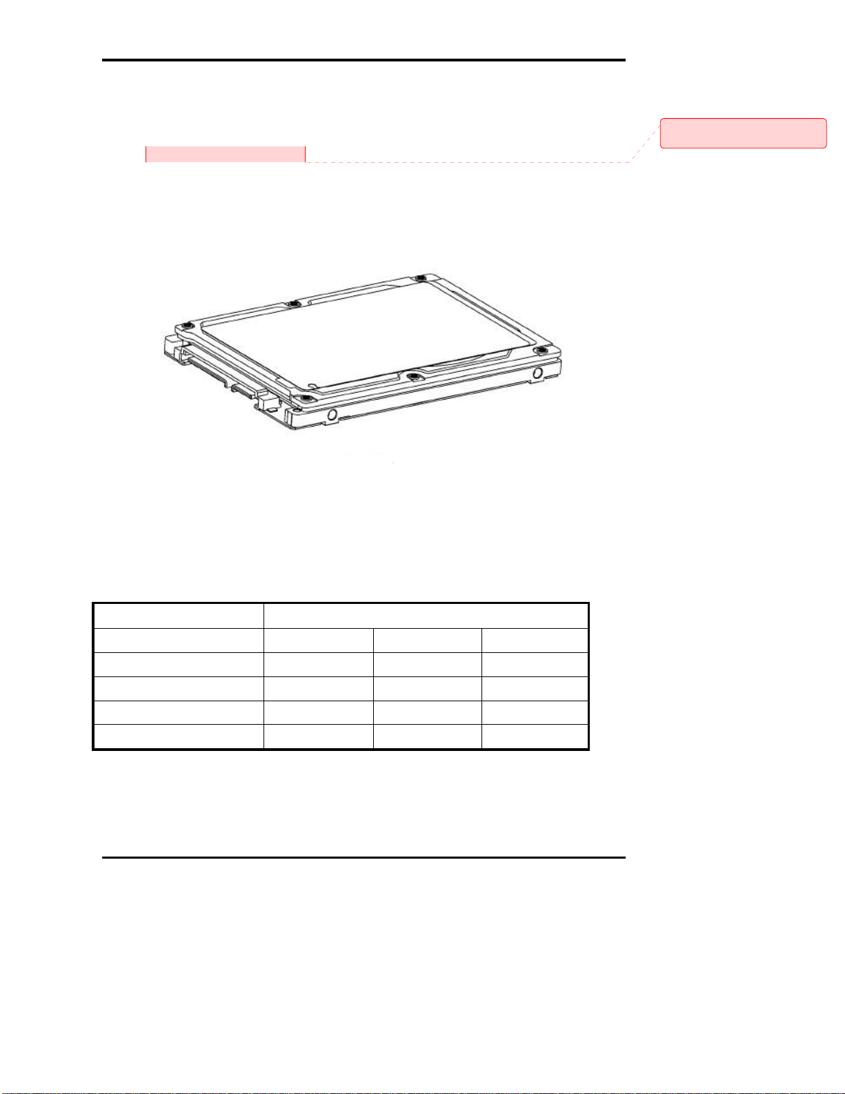
1.3.1 2.5-inch Hard Disk Drive
The removable HDD is a random access non-volatile storage device. It has a non-removable
2.5-inch magnetic disk and mini-Winchester type magnetic heads.
The computer supports a 160GB, 250GB, 320GB, 400GB and 500GB.
The HDD is shown in figure 1-4. Specifications are listed in Table 1-1.
Figure 1-4 2.5-inch HDD
Table 1-1 2.5-inch HDD specifications (1/1)
Item Specifications
Capacity (GB)
160 GB 250 GB 320 GB
Rotational Speed (RPM)
5400 rpm 5400 rpm 5400 rpm
Height
9.5 mm 9.5 mm 9.5 mm
User Data Sectors
312,581,808 488,397,168 625,142,448
Bytes / Sector
512 512 512
Comment [z15]:
Please add SSD information.
1 Hardware Overview
Item Specifications
Capacity (GB)
400 GB 500 GB
Rotational Speed (RPM)
5400 rpm 5400 rpm
Height
9.5 mm 9.5 mm
User Data Sectors
781,422,768 976,773,168
Bytes / Sector
512 512
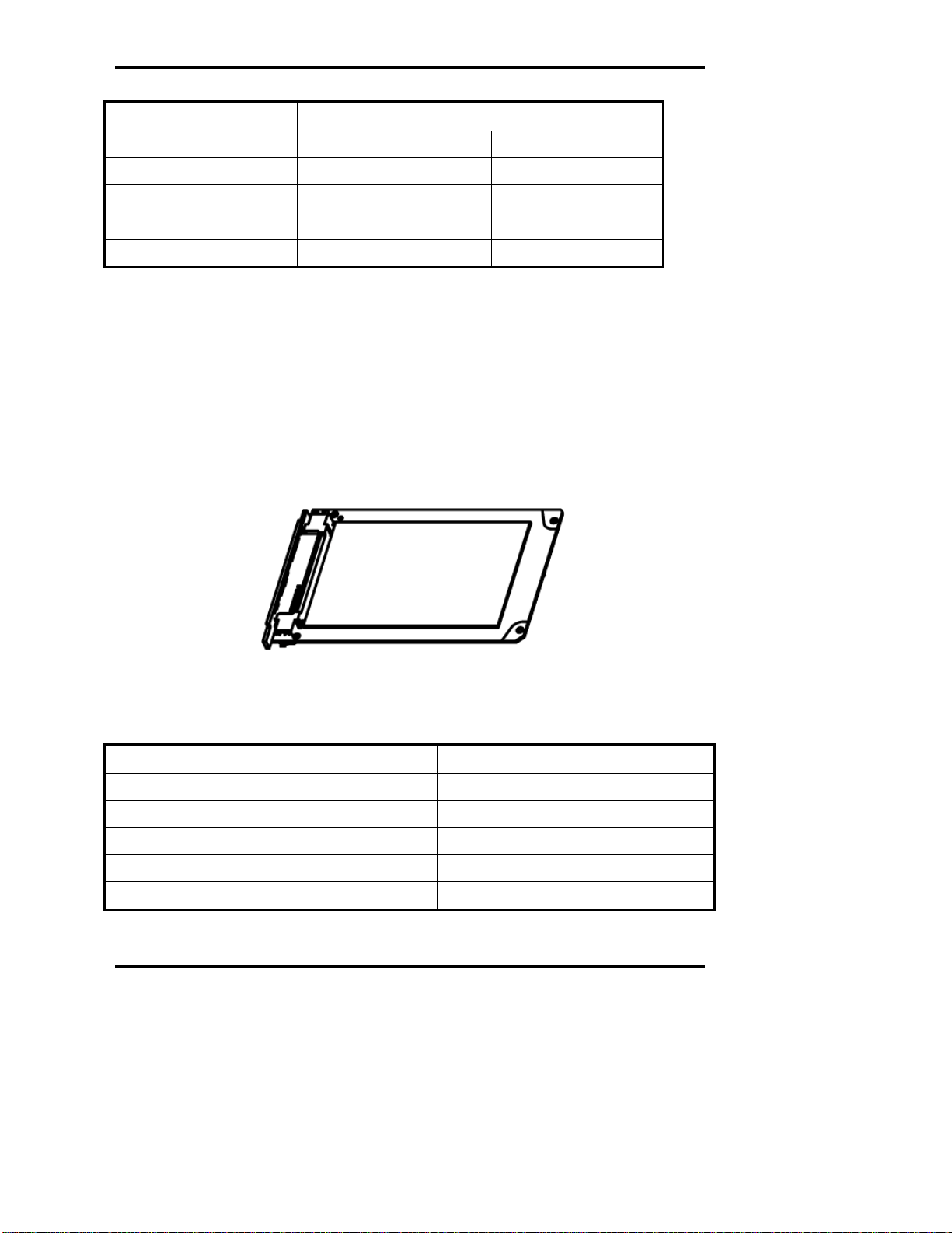
1.3.2 SSD
The solid-state drive (SSD) is a data storage device that uses solid-state memory to store
persistent data. A SSD emulates a hard disk drive interface, thus easily replacing it in most
applications.
The computer supports a dedicated SSD port with TOSHIBA module type SSD.
The SSD is shown in figure 1-5. Specifications are listed in Table 1-2.
Figure 1-5 SSD
Table 1-2 1.8-inch SSD specifications (1/1).
Item Specifications
Capacity (GB)
64 GB
Number of data heads
16
Number of user data cylinders
16,383
User Addressable Sectors in LBA Mode
125,045,424
Bytes / Sector
512
1-16 [CONFIDENTIAL] Satellite M500/M505/M507 Maintenance Manual
1 Hardware Overview
Satellite M500/M505/M507 Maintenance Manual [CONFIDENTIAL] 1-17
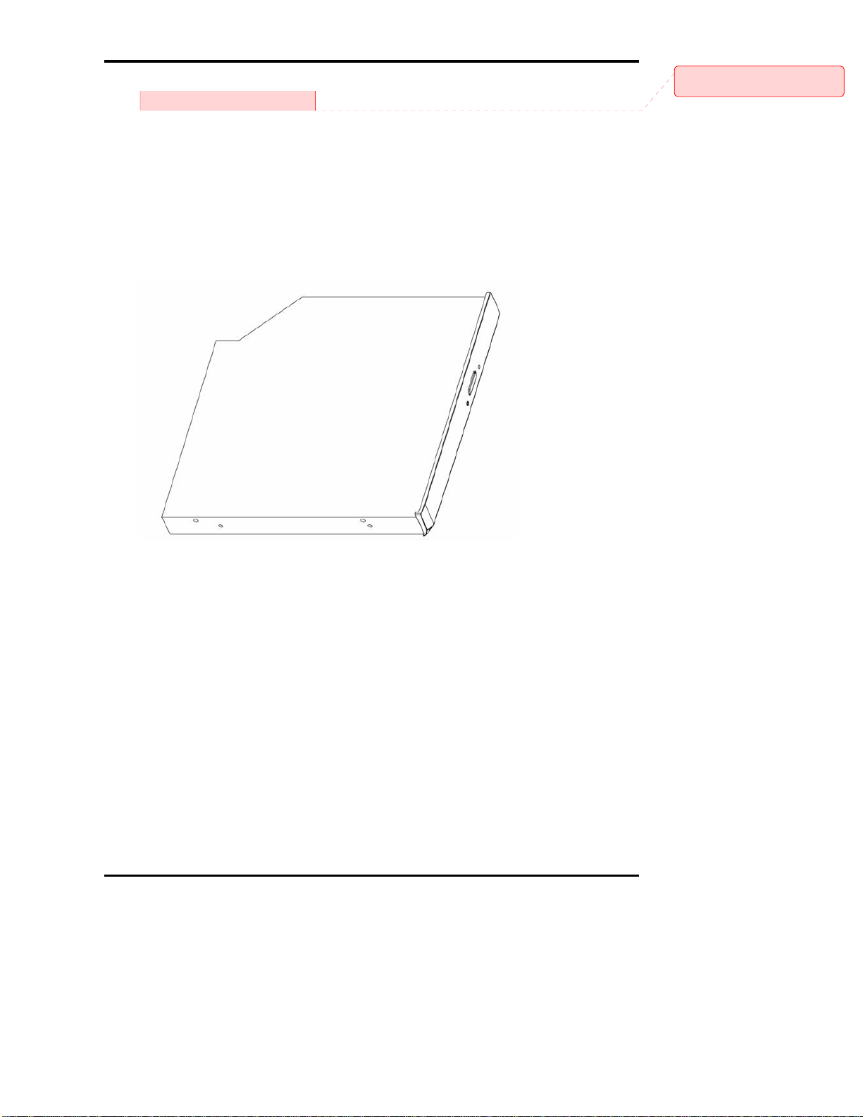
1.4 DVD Super Multi Drive
Comment [z16]:
Please add DVD drive photo.
This drive is a combination of DVD-ROM and DVD±R/±RW/-RAM Drive. It is full-size and
runs either 12cm (4.72-inch) or 8cm (3.15-inch) DVD/CDs without an adaptor. It reads
DVDs at maximum 8x speed and CDs at maximum 24x speed. It also writes CD-R at
maximum 24x speed, CD-RW at maximum 24x speed, DVD±R at maximum 8x speed,
DVD-RW at maximum 6x speed, DVD+RW at maximum 8x speed, DVD±R DL at
maximum 6x speed and DVD-RAM at maximum 3-5x speed.
The DVD is shown in figure 1-6.
Figure 1-6 DVD Super Multi drive
1 Hardware Overview
1-18 [CONFIDENTIAL] Satellite M500/M505/M507 Maintenance Manual
The specifications are listed in Table 1-3.
Table 1-3 DVD Super Multi drive specifications (1/1)
Specifications
Item
DVD-ROM mode CD-ROM mode
SATA Interface (Mbytes/s) 150 Mbyte/s
Average access time (ms) 180ms Typ. 150ms Typ.
Data Buffer Capacity 2MB
Support Formats
CD-DA, CD-ROM
CD-ROM XA
Photo CD (Multi-session)
Video CD, CD-Extra(CD+), CD-Text
DVD-ROM
DVD-R
DVD-Video
DVD-RAM (4.7GB)
DVD+R/RW, DVD+R DL
DVD-RW(Ver. 1.1/1.2)
1 Hardware Overview
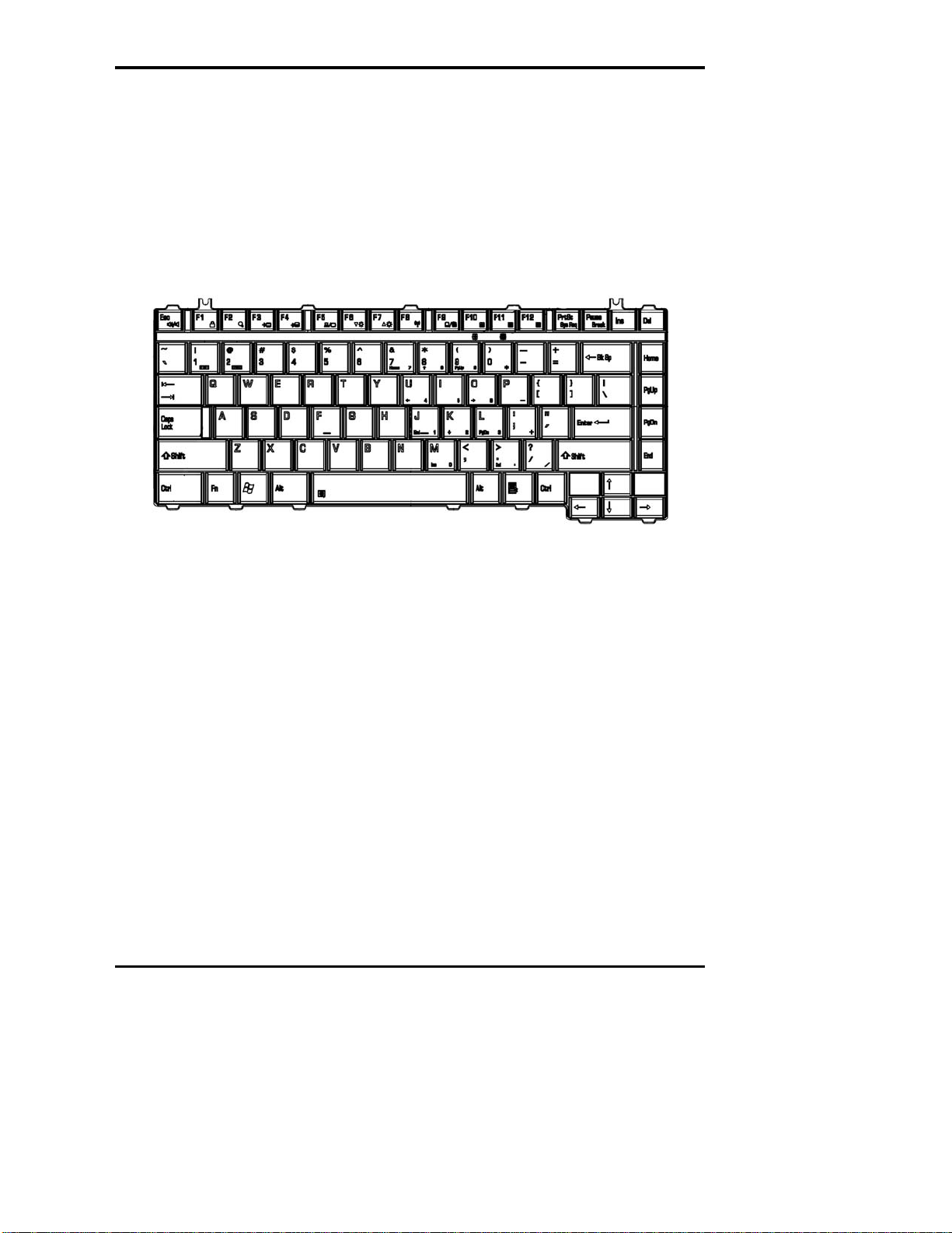
1.5 Keyboard
The keyboard has 86(US)/87(UK) keys that consist of character keys and control keys, and is
in conformity with JIS. The keyboard is connected to a membrane connector on the system
board and is controlled by EC.
Figure 1-7 is a view of the keyboard.
Figure 1-7 Keyboard
Satellite M500/M505/M507 Maintenance Manual [CONFIDENTIAL] 1-19
1 Hardware Overview
1-20 [CONFIDENTIAL] Satellite M500/M505/M507 Maintenance Manual
1.6 TFT Color Display
The TFT color display consists of 14.0-inch LCD module.
The LCD module used for the TFT color display uses a LED backlight as the light source
and can display a maximum of 262,144 colors with 1366*768 resolution.
Table 1-4 lists the specifications.
Table 1-4 LCD module specifications (1/1)
Specifications
Item
14.0" WXGA (1366*768)
CSV type
Number of Dots 1,366 (W) * 768 (H)
Dot spacing (mm) 0.2265(H) * 0.2265(V)
Display range (mm) 309.4(H) * 173.95(V)

1 Hardware Overview
Satellite M500/M505/M507 Maintenance Manual [CONFIDENTIAL] 1-21
1.7 Power Supply
The power supply provides different voltages to the system board and performs the following
functions:
1. Determines that the DC power supply (AC adapter) is connected to the computer.
2. Detects DC output and circuit malfunctions.
3. Controls the battery icon, and DC IN icon.
4. Turns the battery charging system on and off and detects a fully charged battery.
5. Turns the power supply on and off.
6. Provides more accurate detection of a low battery.
7. Calculates the remaining battery capacity.
8. Controls the transmission of the status signal of the main battery.
The power supply output rating is specified in Table 1-5.
Table 1-5 Power supply output rating
Name Voltage (V) Use
+VCORE
VID (Intel spec) CPU
+VCCP 1.05 CPU, GMCH, ICH9-M
+1.5VS
1.5 CPU, GMCH, ICH9-M, Express Card, Mini Card
+1.8V 1.8 GMCH, DDR2-SDRAM
+0.9V 0.9 DDR2-SDRAM
+3VSUS 3.3 ICH9-M, Express Card, Mini Card, LAN, HDMI CEC
+3V 3.3 MDC
+3VS 3.3
Thermal Sensor, Clock gen, LCD, DDR2-SDRAM, ICH9-
M, Express Card, Mini Card, EC, GMCH, Fingerprint, C
Reader, SSD, Bluetooth
ard
+3VA 3.3V EC, SPI ROM
+5VA 5 Function Board
+5VSUS 5 ICH9-M, USB
+5VS 5
FAN, ICH9-M, Audio, ODD, HDD, LED, Touchpad,
Keyboard backlight, CCD, FeliCa, G-sensor
Loading...