


FILE NO. 810-200777GR
SERVICE MANUAL
HDD & DVD Video Recorder
RD-97DTKB
HDD |
DVD |
|
HDD & DVD VIDEO RECORDER RD-97DT |
The above model is classified as a green product (*1), as indicated by the underlined serial number. This Service Manual describes replacement parts for the green product. When repairing this green product, use the part(s) described in this manual and lead-free solder (*2).
For (*1) and (*2), see the next page.
TOSHIBA CORPORATION 2007 |
Published in Japan, August 2007 GREEN |

(*1) |
GREEN PRODUCT PROCUREMENT |
The EC is actively promoting the WEEE & RoHS Directives that define standards for recycling and reuse of Waste Electrical and Electronic Equipment and for the Restriction of the use of certain Hazardous Substances. From July 1, 2006, the RoHS Directive will prohibit any marketing of new products containing the restricted substances.
Increasing attention is given to issues related to the global environmental. Toshiba Corporation recognizes environmental protection as a key management tasks, and is doing its utmost to enhance and improve the quality and scope of its environmental activities. In line with this, Toshiba proactively promotes Green Procurement, and seeks to purchase and use products, parts and materials that have low environmental impacts.
Green procurement of parts is not only confined to manufacture. The same green parts used in manufacture must also be used as replacement parts.
(*2) |
LEAD-FREE SOLDER |
This product is manufactured using lead-free solder as a part of a movement within the consumer products industry at large to be environmentally responsible. Lead-free solder must be used in the servicing and repair of this product.
WARNING
This product is manufactured using lead free solder.
DO NOT USE LEAD BASED SOLDER TO REPAIR THIS PRODUCT !
The melting temperature of lead-free solder is higher than that of leaded solder by 86°F to 104°F (30°C to 40°C). Use of a soldering iron designed for lead-based solders to repair product made with lead-free solder may result in damage to the component and or BOARD being soldered. Great care should be made to ensure high-quality soldering when servicing this product — especially when soldering large components, through-hole pins, and on BOARDs — as the level of heat required to melt lead-free solder is high.

IMPORTANT SAFETY NOTICE
Proper service and repair is important to the safe, reliable operation of all TOSHIBA Equipment. The service procedures recommended by TOSHIBA and described in this service manual are effective methods of performing service operations. Some of these service special tools should be used when and as recommended.
It is important to note that this service manual contains various CAUTIONS and NOTICES which should be carefully read in order to minimize the risk of personal injury to service personnel. The possibility exists that improper service methods may damage the equipment. It also is important to understand that these CAUTIONS and NOTICES ARE NOT EXHAUSTIVE. TOSHIBA could not possibly know, evaluate and advice the service trade of all conceivable ways in which service might be done or of the possible hazardous consequences of each way. Consequently, TOSHIBA has not undertaken any such broad evaluation. Accordingly, a servicer who uses a service procedure or tool which is not recommended by TOSHIBA must first use all precautions thoroughly so that neither his safety nor the safe operation of the equipment will be jeopardized by the service method selected.
TABLE OF CONTENTS
Specifications . . . . . . . . . . . . . . . . . . . . . . . . . . . . . . . . . . . . . . . . . . . . . . . . . . . . . . . . . . . . . . . . . . . . . . . . . . 1-1-1 Laser Beam Safety Precautions. . . . . . . . . . . . . . . . . . . . . . . . . . . . . . . . . . . . . . . . . . . . . . . . . . . . . . . . . . . . 1-2-1 Important Safety Precautions. . . . . . . . . . . . . . . . . . . . . . . . . . . . . . . . . . . . . . . . . . . . . . . . . . . . . . . . . . . . . . 1-3-1 Standard Notes for Servicing . . . . . . . . . . . . . . . . . . . . . . . . . . . . . . . . . . . . . . . . . . . . . . . . . . . . . . . . . . . . . . 1-4-1 Handling Precautions for HDD . . . . . . . . . . . . . . . . . . . . . . . . . . . . . . . . . . . . . . . . . . . . . . . . . . . . . . . . . . . . . 1-5-1 Cabinet Disassembly Instructions . . . . . . . . . . . . . . . . . . . . . . . . . . . . . . . . . . . . . . . . . . . . . . . . . . . . . . . . . . 1-6-1 How to Self-Check and Initialize the HDD & DVD Video Recorder . . . . . . . . . . . . . . . . . . . . . . . . . . . . . . . . . 1-7-1 Firmware Renewal Mode . . . . . . . . . . . . . . . . . . . . . . . . . . . . . . . . . . . . . . . . . . . . . . . . . . . . . . . . . . . . . . . . . 1-8-1 Troubleshooting . . . . . . . . . . . . . . . . . . . . . . . . . . . . . . . . . . . . . . . . . . . . . . . . . . . . . . . . . . . . . . . . . . . . . . . . 1-9-1 Function Indicator Symbols . . . . . . . . . . . . . . . . . . . . . . . . . . . . . . . . . . . . . . . . . . . . . . . . . . . . . . . . . . . . . . 1-10-1 Block Diagrams . . . . . . . . . . . . . . . . . . . . . . . . . . . . . . . . . . . . . . . . . . . . . . . . . . . . . . . . . . . . . . . . . . . . . . . 1-11-1 Schematic Diagrams / BOARD’s and Test Points . . . . . . . . . . . . . . . . . . . . . . . . . . . . . . . . . . . . . . . . . . . . . 1-12-1 Waveforms . . . . . . . . . . . . . . . . . . . . . . . . . . . . . . . . . . . . . . . . . . . . . . . . . . . . . . . . . . . . . . . . . . . . . . . . . . . 1-13-1 Wiring Diagram . . . . . . . . . . . . . . . . . . . . . . . . . . . . . . . . . . . . . . . . . . . . . . . . . . . . . . . . . . . . . . . . . . . . . . . 1-14-1 System Control Timing Charts . . . . . . . . . . . . . . . . . . . . . . . . . . . . . . . . . . . . . . . . . . . . . . . . . . . . . . . . . . . . 1-15-1 IC Pin Function Descriptions . . . . . . . . . . . . . . . . . . . . . . . . . . . . . . . . . . . . . . . . . . . . . . . . . . . . . . . . . . . . . 1-16-1 Lead Identifications . . . . . . . . . . . . . . . . . . . . . . . . . . . . . . . . . . . . . . . . . . . . . . . . . . . . . . . . . . . . . . . . . . . . 1-17-1 Exploded Views . . . . . . . . . . . . . . . . . . . . . . . . . . . . . . . . . . . . . . . . . . . . . . . . . . . . . . . . . . . . . . . . . . . . . . . 1-18-1 Mechanical Parts List . . . . . . . . . . . . . . . . . . . . . . . . . . . . . . . . . . . . . . . . . . . . . . . . . . . . . . . . . . . . . . . . . . . 1-19-1 Electrical Parts List . . . . . . . . . . . . . . . . . . . . . . . . . . . . . . . . . . . . . . . . . . . . . . . . . . . . . . . . . . . . . . . . . . . . 1-20-1
Manufactured under license from Dolby Laboratories.
“Dolby” and the double-D symbol are trademarks of Dolby Laboratories.

|
SPECIFICATIONS |
|
|
|
|
General |
|
|
System |
|
HDD, DVD-Video, DVD-RW/-R, DVD+RW/+R, Video CD, |
|
|
CD-DA, CD-RW/-R |
|
|
|
Power requirements |
220–240 V ± 10%, 50 Hz ± 0.5% |
|
|
|
|
Power consumption |
37 W (standby: 7 W) |
|
|
|
|
Weight |
|
3.9 kg |
|
|
|
Dimensions (width x height x depth) |
420 x 59 x 315 mm |
|
|
|
|
Operating temperature |
5°C to 40°C |
|
|
|
|
Operating humidity |
Less than 80% (no condensation) |
|
|
|
|
TV format |
|
PAL-I |
|
|
|
Recording |
|
|
Recording format |
Video Recording (VR) format (DVD-RW only), Video format |
|
|
|
(DVD-RW, DVD-R) |
|
|
+VR format (DVD+RW, DVD+R) |
|
|
|
Recordable discs |
DVD-ReWritable, DVD-Recordable, DVD+ReWritable, |
|
|
|
DVD+Recordable |
|
|
|
Video recording format |
|
|
Sampling frequency |
13.5 MHz |
|
Compression format |
MPEG |
|
|
|
|
Audio recording format |
|
|
Sampling frequency |
48 kHz |
|
Compression format |
Dolby Digital |
|
|
|
|
Tuner |
|
|
Receivable channels |
IRA-E69 (For analogue channels) |
|
|
|
E21-E69 (For DVB-T channels) |
|
|
|
Input/Output |
|
|
Front Panel : (AV3) |
|
|
|
|
|
Video input |
|
One RCA connector |
Input level |
|
1 Vp-p (75 :) |
|
|
|
S-Video input |
One Mini DIN 4-pin jack |
|
Input level |
|
Y (Iuminance) 1 Vp-p (75 :) |
|
|
C (colour) 300 mVp-p (75 :) |
|
|
|
Audio input |
|
Two RCA connectors |
Input level |
|
2 Vrms (input impedance: more than 10 k:) |
|
|
|
DV input |
|
IEEE 1394 |
DV 4-pin jack |
|
|
|
|
|
Rear Panel : |
|
|
|
|
|
ANALOG |
VHF/UHF antenna input/output terminal |
75 : |
DVB-T |
UHF antenna input/output terminal |
75 : |
|
|
|
Audio input /output |
Two 21-pin scart sockets (AV1, AV2) |
|
|
|
|
Video input /output |
Two 21-pin scart sockets (AV1, AV2) |
|
Input /output level |
1 Vp-p (75 :) each |
|
|
|
|
Component video output |
Three RCA connectors |
|
Output level |
Y: 1.0 Vp-p (75 :) |
|
|
|
PB/CB, PR/CR: 0.7 Vp-p (75 :) each |
Audio output |
Two RCA connectors |
|
Output level |
2 Vrms (output impedance: 680 :) |
|
|
|
|
Digital audio output |
One Coaxial pin jack |
|
Output level |
500 mVp-p (75 :) |
|
|
|
|
HDMI output |
HDMI jack |
|
Note
The specifications and design of this product are subject to change without notice.
1-1-1 |
E2J70SP |

LASER BEAM SAFETY PRECAUTIONS
This DVD player uses a pickup that emits a laser beam.
Do not look directly at the laser beam coming from the pickup or allow it to strike against your skin.
The laser beam is emitted from the location shown in the figure. When checking the laser diode, be sure to keep your eyes at least 30 cm away from the pickup lens when the diode is turned on. Do not look directly at the laser beam.
CAUTION: Use of controls and adjustments, or doing procedures other than those specified herein, may result in hazardous radiation exposure.
Drive Mechanism Assembly
Laser Beam Radiation
Laser Pickup 
Turntable 
Location: Inside Top of DVD mechanism.
1-2-1 |
R4PLSP |
IMPORTANT SAFETY PRECAUTIONS
Product Safety Notice
Some electrical and mechanical parts have special safety-related characteristics which are often not evident from visual inspection, nor can the protection they give necessarily be obtained by replacing them with components rated for higher voltage, wattage, etc. Parts that have special safety characteristics are identified by a !on schematics and in parts lists. Use of a substitute replacement that does not have the same safety characteristics as the recommended replacement part might create shock, fire, and/or other hazards. The Product’s Safety is under review continuously and new instructions are issued whenever appropriate. Prior to shipment from the factory, our products are carefully inspected to confirm with the recognized product safety and electrical codes of the countries in which they are to be sold. However, in order to maintain such compliance, it is equally important to implement the following precautions when a set is being serviced.
Precautions during Servicing
A.Parts identified by the ! symbol are critical for safety. Replace only with part number specified.
B.In addition to safety, other parts and assemblies are specified for conformance with regulations applying to spurious radiation. These must also be replaced only with specified replacements.
Examples: RF converters, RF cables, noise blocking capacitors, and noise blocking filters, etc.
C.Use specified internal wiring. Note especially:
1)Wires covered with PVC tubing 2)Double insulated wires
3)High voltage leads
D.Use specified insulating materials for hazardous live parts. Note especially:
1)Insulation tape 2)PVC tubing 3)Spacers
4)Insulators for transistors
E.When replacing AC primary side components (transformers, power cord, etc.), wrap ends of wires securely about the terminals before soldering.
F.Observe that the wires do not contact heat producing parts (heatsinks, oxide metal film resistors, fusible resistors, etc.).
G.Check that replaced wires do not contact sharp edges or pointed parts.
H.When a power cord has been replaced, check that 5 - 6 kg of force in any direction will not loosen it.
I.Also check areas surrounding repaired locations.
J.Be careful that foreign objects (screws, solder droplets, etc.) do not remain inside the set.
K.When connecting or disconnecting the internal connectors, first, disconnect the AC plug from the AC outlet.
1-3-1 |
DVD_SFNP |
Safety Check after Servicing
Examine the area surrounding the repaired location for damage or deterioration. Observe that screws, parts, and wires have been returned to their original positions. Afterwards, do the following tests and confirm the specified values to verify compliance with safety standards.
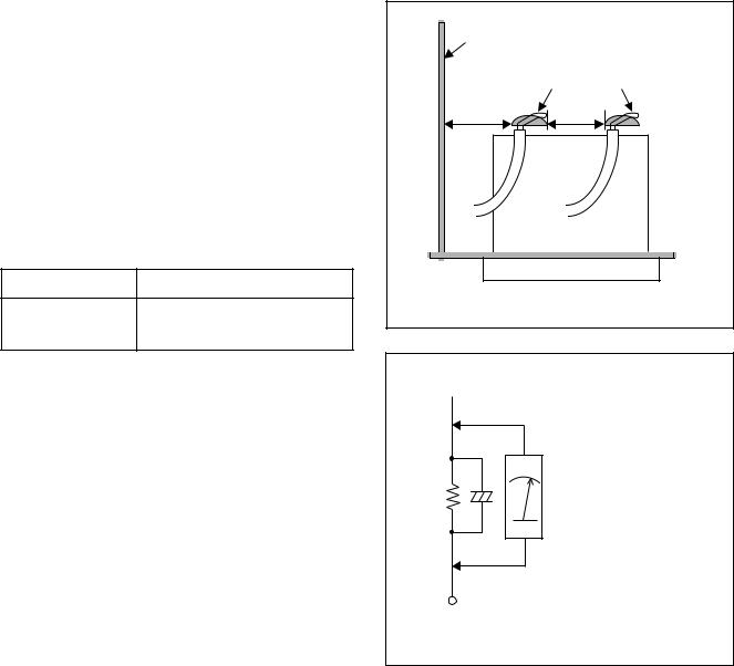
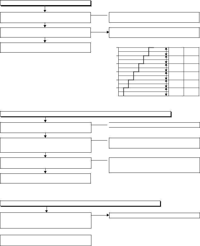
1. Clearance Distance
When replacing primary circuit components, confirm specified clearance distance (d) and (d’) between soldered terminals, and between terminals and surrounding metallic parts. (See Fig. 1)
Table 1 : Ratings for selected area
AC Line Voltage |
Clearance Distance (d), (d’) |
≥ 3 mm(d) 220 to 240 V ≥
6 mm(d’)
Chassis or Secondary Conductor |
|
|
Primary Circuit |
d' |
d |
Fig. 1
Note: This table is unofficial and for reference only. Be sure to confirm the precise values.
2. Leakage Current Test
Confirm the specified (or lower) leakage current between B (earth ground, power cord plug prongs) and externally exposed accessible parts (RF terminals, antenna terminals, video and audio input and output terminals, microphone jacks, earphone jacks, etc.) is lower than or equal to the specified value in the table below.
Measuring Method (Power ON) :
Insert load Z between B (earth ground, power cord plug prongs) and exposed accessible parts. Use an AC voltmeter to measure across the terminals of load Z. See Fig. 2 and the following table.
Table 2: Leakage current ratings for selected areas
 Exposed Accessible Part
Z |
AC Voltmeter |
|
(High Impedance) |
||
|
BOne side of
Power Cord Plug Prongs
Fig. 2
AC Line Voltage |
Load Z |
Leakage Current (i) |
One side of power cord plug |
||
prongs (B) to: |
|||||
|
|
|
|
||
|
|
|
|
|
|
|
|
2kΩ RES. |
i≤0.7mA AC Peak |
RF or |
|
|
|
Connected in |
|||
|
|
i≤2mA DC |
Antenna terminals |
||
|
|
parallel |
|||
220 to 240 V |
|
|
|
||
|
|
|
|
||
|
50kΩ RES. |
i≤0.7mA AC Peak |
A/V Input, Output |
||
|
|
||||
|
|
Connected in |
|||
|
|
i≤2mA DC |
|||
|
|
parallel |
|
||
|
|
|
|
||
|
|
|
|
|
|
Note: This table is unofficial and for reference only. Be sure to confirm the precise values.
1-3-2 |
DVD_SFNP |
STANDARD NOTES FOR SERVICING
NOTE: BOARD MEANS PRINTED CIRCUIT BOARD.
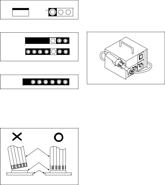
Circuit Board Indications |
Pb (Lead) Free Solder |
1. The output pin of the 3 pin Regulator ICs is |
When soldering, be sure to use the Pb free solder. |
indicated as shown. |
|
Top View |
Bottom View |
Out |
Input |
In |
2.For other ICs, pin 1 and every fifth pin are indicated as shown.
5
Pin 1 


10
3.The 1st pin of every male connector is indicated as shown.
Pin 1 

Instructions for Connectors
1.When you connect or disconnect the FFC (Flexible Foil Connector) cable, be sure to first disconnect the AC cord.
2.FFC (Flexible Foil Connector) cable should be inserted parallel into the connector, not at an angle.
FFC Cable
Connector
BOARD
How to Remove / Install Flat Pack-IC
1. Removal
With Hot-Air Flat Pack-IC Desoldering Machine:
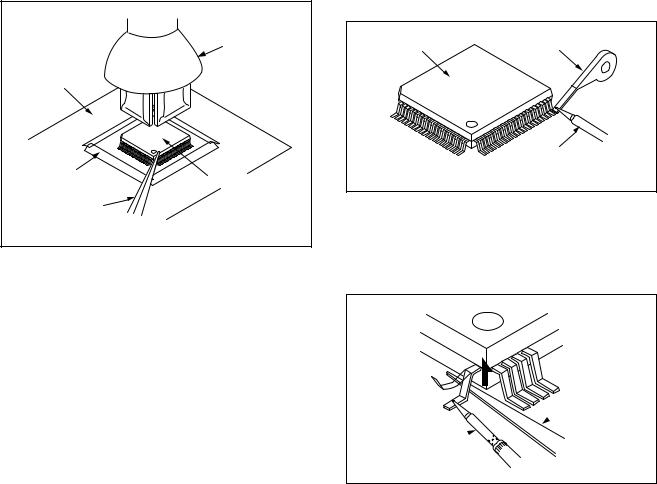
1.Prepare the hot-air flat pack-IC desoldering machine, then apply hot air to the Flat Pack-IC (about 5 to 6 seconds). (Fig. S-1-1)
Fig. S-1-1
2.Remove the flat pack-IC with tweezers while applying the hot air.
3.Bottom of the flat pack-IC is fixed with glue to the BOARD; when removing entire flat pack-IC, first apply soldering iron to center of the flat pack-IC and heat up. Then remove (glue will be melted). (Fig. S-1-6)
4.Release the flat pack-IC from the BOARD using tweezers. (Fig. S-1-6)
CAUTION:
1.The Flat Pack-IC shape may differ by models. Use an appropriate hot-air flat pack-IC desoldering machine, whose shape matches that of the Flat Pack-IC.
2.Do not supply hot air to the chip parts around the flat pack-IC for over 6 seconds because damage to the chip parts may occur. Put masking tape around the flat pack-IC to protect other parts from damage. (Fig. S-1-2)
* Be careful to avoid a short circuit.
1-4-1 |
DVDP_SN |
3.The flat pack-IC on the BOARD is affixed with glue, so be careful not to break or damage the foil of each pin or the solder lands under the IC when removing it.
|
Hot-air |
|
Flat Pack-IC |
|
Desoldering |
BOARD |
Machine |
|
|
Masking |
Flat Pack-IC |
Tape |
|
Tweezers |
|
|
Fig. S-1-2 |
With Soldering Iron:
1.Using desoldering braid, remove the solder from all pins of the flat pack-IC. When you use solder flux which is applied to all pins of the flat pack-IC, you can remove it easily. (Fig. S-1-3)
Flat Pack-IC |
Desoldering Braid |
|
Soldering Iron
Fig. S-1-3
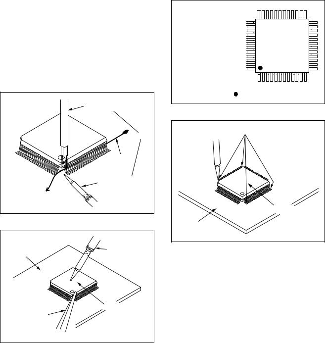
2.Lift each lead of the flat pack-IC upward one by one, using a sharp pin or wire to which solder will not adhere (iron wire). When heating the pins, use a fine tip soldering iron or a hot air desoldering machine. (Fig. S-1-4)
Sharp
 Pin
Pin
Fine Tip 
Soldering Iron
Fig. S-1-4
3.Bottom of the flat pack-IC is fixed with glue to the BOARD; when removing entire flat pack-IC, first apply soldering iron to center of the flat pack-IC and heat up. Then remove (glue will be melted). (Fig. S-1-6)
4.Release the flat pack-IC from the BOARD using tweezers. (Fig. S-1-6)
1-4-2 |
DVDP_SN |
With Iron Wire:
1.Using desoldering braid, remove the solder from all pins of the flat pack-IC. When you use solder flux which is applied to all pins of the flat pack-IC, you can remove it easily. (Fig. S-1-3)
2.Affix the wire to a workbench or solid mounting point, as shown in Fig. S-1-5.
3.While heating the pins using a fine tip soldering iron or hot air blower, pull up the wire as the solder melts so as to lift the IC leads from the BOARD contact pads as shown in Fig. S-1-5.
4.Bottom of the flat pack-IC is fixed with glue to the BOARD; when removing entire flat pack-IC, first apply soldering iron to center of the flat pack-IC and heat up. Then remove (glue will be melted). (Fig. S-1-6)
5.Release the flat pack-IC from the BOARD using tweezers. (Fig. S-1-6)
Note: When using a soldering iron, care must be taken to ensure that the flat pack-IC is not being held by glue. When the flat pack-IC is removed from the BOARD, handle it gently because it may be damaged if force is applied.
Hot Air Blower |
or |
Iron Wire |
Soldering Iron |
To Solid |
Mounting Point |
Fig. S-1-5 |
BOARD |
Fine Tip |
Soldering Iron |
|
|
Flat Pack-IC |
Tweezers |
|
|
Fig. S-1-6 |
2. Installation
1.Using desoldering braid, remove the solder from the foil of each pin of the flat pack-IC on the BOARD so you can install a replacement flat packIC more easily.
2.The “●” mark on the flat pack-IC indicates pin 1. (See Fig. S-1-7.) Be sure this mark matches the 1 on the BOARD when positioning for installation. Then presolder the four corners of the flat pack-IC. (See Fig. S-1-8.)
3.Solder all pins of the flat pack-IC. Be sure that none of the pins have solder bridges.
Example :
Pin 1 of the Flat Pack-IC |
|
is indicated by a " " mark. |
Fig. S-1-7 |
|
Presolder |
Flat Pack-IC |
BOARD |
Fig. S-1-8 |
1-4-3 |
DVDP_SN |
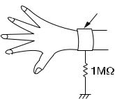
Instructions for Handling Semiconductors
Electrostatic breakdown of the semi-conductors may occur due to a potential difference caused by electrostatic charge during unpacking or repair work.
1. Ground for Human Body
Be sure to wear a grounding band (1 MΩ) that is properly grounded to remove any static electricity that may be charged on the body.
2. Ground for Workbench
Be sure to place a conductive sheet or copper plate with proper grounding (1 MΩ) on the workbench or other surface, where the semi-conductors are to be placed. Because the static electricity charge on clothing will not escape through the body grounding band, be careful to avoid contacting semi-conductors with your clothing.
<Incorrect> |
|
|
BOARD |
<Correct> |
Grounding Band |
|
1MΩ |
|
BOARD |
1MΩ
Conductive Sheet or Copper Plate
1-4-4 |
DVDP_SN |
HANDLING PRECAUTIONS FOR HDD
CAUTION:
1. SHOCK
a.Exposing HDD to shock may be the biggest damaging factor. Please note that HDD is easily damaged even if dropped from any height. Be sure to place HDD on a shock-absorbent mat. Also, be careful when transporting HDD.
b.Be careful not to subject HDD to any shock when tightening screws for HDD replacement.
(Tighten screws manually, not with an electric driver.)
2. MOISTURE
a.Moisture may also be a damaging factor. HDD is semiclosed style. Sudden changes in ambient temperature may cause moisture to form. Monitor temperature and do not allow moisture to form on the media surface. Also, when opening HDD package, do so only after package is at ambient temperature.
b.After replacing HDD, leave it to reach room temperature (about 2 hours) for preventing dew internal condensation, and then work necessary task such as operation check.
3. STATIC ELECTRICITY
a.After removing HDD or taking replacement HDD out of the protective bag (the replacement HDD is packed in a protective bag), place HDD on a conductive surface. A grounding band should be worn when handling.
Grounding Band
Both the conductive surface and grounding band should be grounded.
b.Make sure that HDD is placed on main unit completely and then let go of it, when assembling.
c.Do not put HDD on a packing bag. (for preventing electrostatic damage)
4. OTHERS
a.Be careful so as not to do the followings. Otherwise, HDD might be damaged.
-DO NOT disassemble HDD.
-When handling HDD, be sure to hold both sides securely.
b.HDD should be stored, packed in the protective bag, in suitable surroundings (i.e., no extreme changes in temperature to avoid condensation).
c.When transporting HDD, be sure to use the exclusive packing case (the replacement HDD carton).
d.Do not stack HDDs.
e.Do not place vertically because HDD is unstable and easy to fall.
1-5-1 |
DHD_SN |

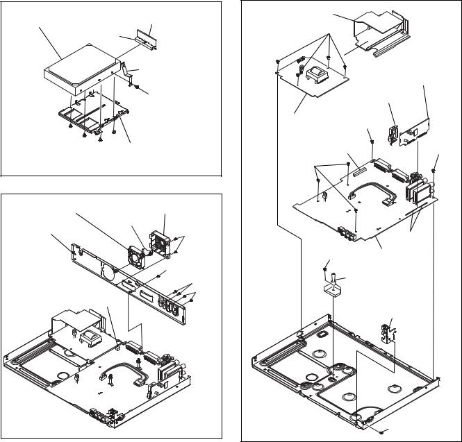
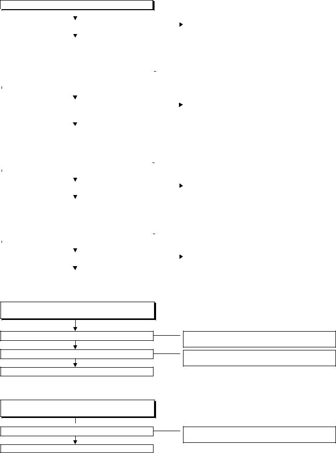
CABINET DISASSEMBLY INSTRUCTIONS
1. Disassembly Flowchart
This flowchart indicates the disassembly steps to gain access to item(s) to be serviced. When reassembling, follow the steps in reverse order. Bend, route, and dress the cables as they were originally.
|
|
|
[1] COVER TOP |
|
|
|
|
|
|
|
|
|
|
|
|
|
|
|
|
|
|
|
|
|
|
|
|
|
|
|
|
[3] BOARD FRONT |
|
|
[2] FRONT |
|
|
[19] FRONT |
|
|
|
ASSEMBLY |
|
|
BRACKET R |
||
|
|
|
|
||||
|
|
|
|
|
|
|
|
[4] BOARD POWER
[5] PANEL FRONT [6] HDD ASSEMBLY
SWITCH
[8] IEEE 1394 |
|
[7] DVD MECHANISM |
|
[9] BOARD ATA |
||||
DV-IN CABLE |
|
|
& DVD/HDD MAIN |
|
||||
|
|
|||||||
|
|
|
|
|||||
|
|
|
|
BOARD ASSEMBLY |
|
|
|
|
|
|
|
|
|
|
|
|
|
|
|
|
|
|
|
|
|
|
[12] FAN COVER |
|
|
[15] BOARD POWER |
|
[10] HDD BRACKET |
|||
|
SUPPLY |
|
||||||
|
|
|
|
|
|
|
||
|
|
|
|
|
|
|
|
|
|
|
|
|
|
|
|
|
|
[13] MOTOR DC |
|
|
[16] BOARD AV |
|
[11] HARD DISK |
|||
FAN |
|
|
|
DRIVE |
||||
|
|
|
|
|||||
|
|
|
|
|
|
|
|
|
|
|
|
|
|
|
|
|
|
[14] PANEL REAR |
|
|
[17] DTV MODULE |
|
|
|
||
|
ASSEMBLY |
|
|
|
||||
|
|
|
|
|
|
|
||
|
|
|
|
|
|
|
|
|
|
|
|
|
|
|
|
|
|
[18]MAIN BOARD HOLDER
2.Disassembly Method
ID/ |
|
|
REMOVAL |
|
|
|
|
|
|
||
|
|
REMOVE/*UNHOOK/ |
|
||
LOC. |
PART |
Fig. |
|
||
UNLOCK/RELEASE/ |
Note |
||||
No. |
|
||||
|
|
No. |
UNPLUG/DESOLDER |
|
|
|
|
|
|
|
|
|
|
|
|
|
|
[1] |
COVER TOP |
D1 |
8(S-1) |
--- |
|
|
|
|
|
|
|
[2] |
FRONT |
D2 |
*CN2204, *5(L-1), |
1 |
|
ASSEMBLY |
*3(L-2) |
||||
|
|
|
|
|
|
[3] |
BOARD |
D3 |
*CN3001-F, 4(S-2A) |
--- |
|
FRONT |
|||||
|
|
|
|
||
|
|
|
|
|
|
|
BOARD |
|
|
|
|
[4] |
POWER |
D3 |
(S-2B) |
--- |
|
|
SWITCH |
|
|
|
|
|
|
|
|
|
|
[5] |
PANEL |
D3 |
---------- |
--- |
|
FRONT |
|||||
|
|
|
|
||
|
|
|
|
|
|
[6] |
HDD |
D4 |
*CN1015, *CN651, |
--- |
|
ASSEMBLY |
3(S-3) |
||||
|
|
|
|
|
|
|
DVD |
|
(S-4), 4(S-5), (S-6), |
|
|
|
|
*CN101, *CN503, |
|
||
|
MECHANISM |
|
|
||
|
|
*CN701, *CN901, |
|
||
|
& DVD/HDD |
|
|
||
[7] |
D4 |
BOARD SUPPORT/ |
2 |
||
MAIN |
|||||
|
|
BOARD SPACERS, |
|
||
|
BOARD |
|
|
||
|
|
M-BOARD PLATE |
|
||
|
ASSEMBLY |
|
|
||
|
|
EARTH |
|
||
|
|
|
|
||
|
|
|
|
|
|
|
IEEE 1394 |
|
2(S-7), DV PLATE |
|
|
[8] |
DV-IN |
D4 |
--- |
||
|
CABLE |
|
EARTH |
|
|
|
|
|
|
||
|
|
|
|
|
ID/ |
|
|
REMOVAL |
|
|
|
|
|
|
||
|
|
REMOVE/*UNHOOK/ |
|
||
LOC. |
PART |
Fig. |
|
||
UNLOCK/RELEASE/ |
Note |
||||
No. |
|
||||
|
|
No. |
UNPLUG/DESOLDER |
|
|
|
|
|
|
|
|
|
|
|
|
|
|
[9] |
BOARD ATA |
D5 |
*CN3001-A |
--- |
|
|
|
|
|
|
|
[10] |
HDD |
D5 |
4(S-8) |
--- |
|
BRACKET |
|||||
|
|
|
|
||
|
|
|
|
|
|
[11] |
HARD DISK |
D5 |
(S-9), HDD PLATE |
3 |
|
DRIVE |
EARTH |
||||
|
|
|
|
|
|
[12] |
FAN COVER |
D6 |
2(S-10) |
--- |
|
|
|
|
|
|
|
[13] |
MOTOR DC |
D6 |
FAN EARTH, |
--- |
|
|
FAN |
|
*CN1601 |
|
|
|
|
|
|
|
|
[14] |
PANEL |
D6 |
(S-11), 2(S-12), |
--- |
|
REAR |
2(S-13) |
||||
|
|
|
|
|
|
|
BOARD |
|
*CN1152, 4(S-14), |
|
|
[15] |
POWER |
D7 |
--- |
||
POWER HOLDER |
|||||
|
SUPPLY |
|
|
|
|
|
|
|
|
|
|
[16] |
BOARD AV |
D7 |
5(S-15) |
--- |
|
|
|
|
|
|
|
|
DTV |
|
DESOLDER, |
|
|
[17] |
MODULE |
D7 |
MODULE BOARD |
--- |
|
|
ASSEMBLY |
|
HOLDER |
|
|
|
|
|
|
|
|
|
MAIN |
|
|
|
|
[18] |
BOARD |
D7 |
(S-16) |
--- |
|
|
HOLDER |
|
|
|
|
|
|
|
|
|
|
[19] |
FRONT |
D7 |
(S-17) |
--- |
|
BRACKET R |
|||||
|
|
|
|
|
|
↓ |
↓ |
↓ |
↓ |
↓ |
|
(1) |
(2) |
(3) |
(4) |
(5) |
Note:
(1): Identification (location) No. of parts in the figures (2): Name of the part
(3): Figure Number for reference
(4): Identification of parts to be removed, unhooked, unlocked, released, unplugged, unclamped, or desoldered.
P=Spring, L=Locking Tab, S=Screw, CN=Connector
*=Unhook, Unlock, Release, Unplug, or Desolder e.g. 7(S-1) = seven Screws (S-1),
5(L-1) = five Locking Tabs (L-1) (5): Refer to “Reference Notes.”
1-6-1 |
E2J70DC |

Reference Notes
1.Locking Tabs (L-1) ,(L-2) are fragile. Be careful not to break them.
1-1. Release five Locking Tabs (L-1).
1-2. Release three Locking Tabs (L-2) and remove the PANEL FRONT.
2.The DVD MECHANISM & DVD/HDD MAIN BOARD ASSEMBLY is adjusted as a unit at factory. Therefore, do not disassemble it. Replace the DVD MECHANISM & DVD/HDD MAIN BOARD ASSEMBLY as a unit.
3.Whenever you have replaced the Hard Disk Drive, initialize the Hard Disk Drive. To initialize the Hard Disk Drive, perform the following.
3-1. To put the HDD & DVD Video Recorder into the HDD mode, press the [HDD] button on the remote control unit.
3-2. To put the HDD & DVD Video Recorder into the self-check mode, after pressing [VARIABLE SKIP] button, press the [0], [7], and [9] buttons on the remote control unit in that order within three seconds.
3-3. Press [ENTER/OK] button. The HDD & DVD Video Recorder is initialized and the power is turned off automatically after two seconds.
[1] COVER TOP |
(S-1) |
(S-1) |
|
|
(S-1) |
|
(S-1) |
|
Fig. D1 |
(L-1) |
|
(L-1) |
|
CN2204 |
|
|
(L-1) |
(L-2) |
|
[2] FRONT ASSEMBLY |
Fig. D2 |
|
[4] BOARD POWER SWITCH


 (S-2B)
CN3001-F (S-2A)
(S-2A)
 [3] BOARD
FRONT
[5] PANEL FRONT
Fig. D3
[7] *DVD MECHANISM (S-4) |
M-BOARD PLATE |
|
& DVD/HDD MAIN |
EARTH |
|
BOARD ASSEMBLY |
||
|
||
|
CN503 |
|
(S-5) |
CN651 |
|
|
||
(S-5) |
CN101 |
|
CN701 |
||
CN901 |
||
|
[6] HDD |
|
|
ASSEMBLY |
|
(S-3) |
||
(S-3)
 (S-6)
(S-6)
[8] IEEE 1394 |
CN1015 |
|
|
BOARD SUPPORT |
|||
DV-IN CABLE |
|||
(S-7) |
/ BOARD SPACERS |
||
DV PLATE EARTH |
Fig. D4 |
||
|
|||
*See Reference Notes 2. |
|||
|
|||
1-6-2 |
E2J70DC |
[11] HARD DISK DRIVE |
[9] BOARD ATA |
|
|
CN3001-A |
|
|
HDD PLATE EARTH |
|
(S-9) |
(S-8)  [10] HDD BRACKET
Fig. D5
[13] MOTOR DC FAN |
[12] FAN COVER |
FAN EARTH |
|
[14] PANEL REAR |
(S-10) |
|
|
|
(S-11) |
|
(S-12) |
|
(S-13) |
CN1601 |
|
|
Fig. D6 |
POWER HOLDER |
|
|
|
(S-14) |
|
|
|
|
[17] DTV MODULE |
||
|
ASSEMBLY |
|
|
|
MODULE BOARD |
|
|
|
HOLDER |
|
|
[15] BOARD |
(S-15) |
|
|
|
|
|
|
POWER SUPPLY |
|
|
|
CN1152 |
|
(S-15) |
|
(S-15) |
|
|
|
|
DESOLDER |
||
(S-16) [16] BOARD AV |
|
||
|
[18] MAIN BOARD |
|
|
|
HOLDER |
|
|
|
[19] FRONT |
|
|
|
BRACKET R |
||
|
(S-17) |
Fig. D7 |
|
|
|
||
1-6-3 |
E2J70DC |
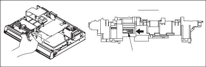
3. How to Eject Manually
Note: When rotating the gear, be careful not to damage the gear.
1.Remove the COVER TOP.
2.Rotate the gear in the direction of the arrow manually as shown below until the tray descends.
3.Pull the tray out manually and remove a disc.
View for A |
A |
Rotate this gear in |
the direction of the arrow |
1-6-4 |
E2J70DC |

HOW TO SELF-CHECK AND INITIALIZE THE HDD & DVD VIDEO
RECORDER
1.Turn on the HDD & DVD Video Recorder.
2.To put the HDD & DVD Video Recorder into the HDD mode, press [HDD] on the remote control unit.
3.To put the HDD & DVD Video Recorder into the self-check mode, after pressing [VARIABLE SKIP] button, press the [0], [7], and [9] buttons on the remote control unit in that order within three seconds.
Fig. a appears on the screen and all LEDs light.
SELF CHECK
*1  DVD CONNECT STATUS : --
*2  HDD CONNECT STATUS : --
*3  HDD POWER ON HOURS :
POWER OFF : POWER
|
Fig. a: Self-Check Mode Screen |
Table 1: Description of Fig. a |
|
|
|
INDICATION |
DESCRIPTION |
|
|
|
|
DVD CONNECT STATUS (*1) |
Connecting Condition of DVD(F/E) |
|
|
HDD CONNECT STATUS (*2) |
Connecting Condition of HDD |
|
|
|
Value of HDD power on hours obtained from S.M.A.R.T. command. (If not obtainable, |
HDD POWER ON HOURS (*3) |
value of HDD power on hours is “0”.) |
|
Value in parentheses is the factory setting value. (If no setting, the value is “0”.) |
|
|
4. Upon the self-check completion, Fig. b appears on the screen.
SELF CHECK
*4  DVD CONNECT STATUS : OK
*5  HDD CONNECT STATUS : OK
HDD POWER ON HOURS : 120
*6 |
|
HDD FORMAT : |
ENTER |
|
|||
*7 |
|
POWER OFF : |
POWER |
|
Fig. b: Screen of Finishing Self-Check Mode
1-7-1 |
E2J70INT |
Table 2: Indication of DVD self-check (*4)
INDICATION |
DESCRIPTION |
|
|
|
|
|
|
|
OK |
Connection of DVD is normal. |
|
|
|
|
NOT FOUND |
DVD drive cannot be found. |
|
|
|
|
CABLE ERROR |
FFC cable (connecting to CN401) between the DVD drive and the DVD/HDD MAIN BOARD |
|
is not connected correctly. |
||
|
||
|
|
Table 3: Indication of HDD self-check (*5)
INDICATION |
DESCRIPTION |
|
|
|
|
OK |
Connection of HDD is normal. |
|
|
NOT FOUND |
HDD drive cannot be found. |
|
|
CABLE ERROR |
FFC cable between the BOARD ATA and the HDD drive is not connected correctly. |
|
|
Table 4: Available button in self-check mode |
|
|
|
BUTTON |
DESCRIPTION |
|
|
|
|
ENTER/OK (*6) |
Initialize (only when the self-check mode is complete) |
|
|
STANDBY-ON (*7) |
Turn the power off (when the self-check mode is complete) |
|
|
OTHER |
Not available |
|
|
5.When the self-check mode is complete, press [
 ] button to turn the power off.
When initializing the HDD & DVD Video Recorder, press [ENTER/OK] button. After two seconds, the power is turned off automatically.
NOTE: When initializing, “Current Clock”, “Setup Changing Item”, “Channel Setup”, “Area Setup”, “Program” and “HDD Contents” are initialized.
1-7-2 |
E2J70INT |

FIRMWARE RENEWAL MODE
1.Turn the power on and remove the disc on the tray.
2.To put the HDD & DVD Video Recorder into version up mode, press [VARIABLE SKIP], [6], [5], and [4] buttons on the remote control unit in the order. Then the tray will open automatically.
Fig. a appears on the screen and Fig. b appears on the VFD.
* Firmware Version differs depending on the models, and this indication is one example.
Firm Update Mode |
ver. HD4T*****Z2B |
|
Current |
|
|||
|
|
|
F/W version |
|
|
|
is displayed. |
Please insert a disc. |
|
|
|
Fig. a Version Up Mode Screen
Fig. b VFD in Version Up Mode
3.Load the disc for version up.
Fig. c appears on the screen. The file on the top is highlighted as the default.
When there is only one file to exist, Step 4 will start automatically.
*Firmware Version differs depending on the models, and this indication is one example.
Firm Update Mode |
ver. HD4T*****Z2B |
Disc name VOL_200707050934
is displayed.
1 HD4T10210Z2B
2 HD4T10211Z2B
3 HD4T10212Z2B
4 HD4T10213Z2B
1 / 1
Fig. c Update Disc Screen
Files included in the disc are displayed.
4.Select the firmware version pressing arrow buttons, then press [ENTER/OK].
Fig. d appears on the screen and Fig. e appears on the VFD. The HDD & DVD Video Recorder starts updating.
About VFD indication of Fig. e:
1)When Fig. d is displayed on the screen, “F-UP” is displayed on the VFD.
2)When “Firmware Updating... XX% Complete.” is displayed on the screen, “02110” is displayed on the VFD.
* Firmware Version differs depending on the models, and this indication is one example.
Firm Update Mode |
ver. HD4T*****Z2B |
(*1) |
File Loading... |
Fig. d Programming Mode Screen
Fig. e VFD in Programming Mode (Example)
The appearance shown in (*1) of Fig. d is described as follows.
No. |
Appearance |
State |
|
|
|
|
|
|
1 |
File Loading... |
Sending files into the memory |
|
|
|
|
Firmware |
|
2 |
Updating... |
Writing new version data |
|
XX% Complete. |
|
|
|
|
--- |
Error |
Failed in updating |
|
|
|
5.After updating is finished, the tray opens automatically.
At this time, no button is available.
6.Pull out the AC code once, then insert it again.
1-8-1 |
E2J70FW |
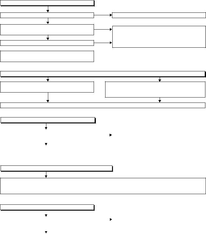
TROUBLESHOOTING
NOTE: BOARD MEANS PRINTED CIRCUIT BOARD.
FLOW CHART NO.1
The power cannot be turned on.
No
Is the fuse normal?
Yes
Is normal state restored when once unplugged No power cord is plugged again after several seconds.
Yes
Is the AL+5V(1) line voltage normal?
No
 Yes
Yes
Check each rectifying circuit of secondary circuit and service it if defective.
See FLOW CHART No.2 <The fuse blows out.>
Check for lead or short-circuiting of primary circuit component and service it if defective. (Q2101, Q2102, T2001, D2001, D2002, D2003, D2004, R2101, R2102, R2103, R2104, R2105)
FLOW CHART NO.2
The fuse blows out.
Check the presence that the primary component is leaking or shorted and service it if defective.
Check the presence that the rectifying diode or circuit is shorted in each rectifying circuit of secondary side and service it if defective.
After servicing, replace the fuse.
FLOW CHART NO.3
When the output voltage fluctuates.
Does the secondary side photo coupler circuit |
No |
Check the circuit and service it if defective. |
||
operate normally? |
|
|
(IC2101, IC2201, D2212, D2238, D2240) |
|
|
|
|
|
|
|
Yes |
|
|
|
|
|
|
|
|
Check the circuit and service it if defective. |
|
|
|
|
(IC2101, D2111, D2112, D2113) |
|
|
|
|
|
|
|
|
|
FLOW CHART NO.4
When buzz sound can be heard in the vicinity of power circuit.
Check if there is short circuit on the rectifying diode and the circuit in each rectifying circuit of secondary side and service it if defective. (D2201, D2202, D2203, D2204, D2205, D2206, D2207, D2208, D2209, D2231, D2232, D2233, IC1025, IC1151, IC1152, Q1015, Q1154, Q1155, Q1156, Q1159, Q1160, Q1163, Q1508, Q1573, Q2203)
FLOW CHART NO.5
-FL is not outputted.
|
|
No |
|
|
|
|
|||
Is the supply voltage of -30V fed to the anode of |
|
|
Check D2201 and their periphery, and service it if |
|
D2201? |
|
|
defective. |
|
|
|
|
|
|
|
Yes |
|
|
|
|
|
|
|
|
Check for load circuit short-circuiting or leak, and |
|
|
|
|
service it if defective. |
|
|
|
|
|
|
|
|
|
1-9-1 |
E2J70TR |
FLOW CHART NO.6
AUDIO+10V is not outputted.
|
|
|
Yes |
Check Q1160, D1162 and their periphery, and |
|
|
Is 12V voltage supplied to the collector of Q1160? |
||||
|
|
|
service it if defective. |
||
|
|
No |
|
|
|
|
|
|
|
|
|
|
|
|
|
|
|
|
|
|
No |
Check D2204, D2205, D2212, C2204 and their |
|
|
|
|
|||
|
Is 12V voltage supplied to the collector of Q2203? |
||||
|
|
|
periphery, and service it if defective. |
||
|
|
Yes |
|
|
|
|
|
|
|
|
|
|
|
|
|
|
|
|
Check Q2203, IC2204 and their periphery, and |
|
|
|
|
|
service it if defective. |
|
|
|
|
|
|
|
|
|
|
|
FLOW CHART NO.7 |
|
|
|
|
|
|
|
|
|
|
|
AL+9V is not outputted. |
|
|
|
|
|
|
|
No |
|
|
|
|
|
Check D2204, D2205, D2212, C2204 |
||
|
|
|
|||
|
Is 12V voltage supplied to the collector of Q1156? |
||||
|
|
|
TTand their periphery, and service it if defective. |
||
|
|
Yes |
|
|
|
|
|
|
|
|
|
|
|
|
|
|
|
|
Check Q1156, D1156 and their periphery, and |
|
|
|
|
|
service it if defective. |
|
|
|
|
|
|
|
|
|
|
|
FLOW CHART NO.8 |
|
|
|
|
|
P-ON+5V is not outputted. |
|
|
|
|
|
(AUDIO+10V is outputted normally.) |
|
|
|
|
|
|
|
|
|
|
|
|
|
|
|
|
|
|
|
No |
Check D2206, D2207, D2213, C2205, C2216 |
|
|
|
|
|||
|
Is 5V voltage supplied to the collector of Q1154? |
||||
|
|
|
and their periphery, and service it if defective. |
||
|
|
Yes |
|
|
|
|
|
|
|
|
|
|
|
|
|
|
|
|
Check Q1154 and their periphery, and service it if |
|
|
|
|
|
defective. |
|
|
|
|
|
|
|
|
|
|
|
FLOW CHART NO.9 |
|
|
|
|
|
EV+32V is not outputted. |
|
|
|
|
|
|
|
|
|
|
|
|
|
No |
Check D2202, D2229, L2202 and their periphery, |
|
|
|
|
|||
|
Is the supply voltage 44V fed the cathode of D2202 |
||||
|
|
|
and service it if defective. |
||
|
|
Yes |
|
|
|
|
|
|
|
|
|
|
|
|
|
|
|
|
Check D1701 and their periphery and service it |
|
|
|
|
|
if defective. |
|
|
|
|
FLOW CHART NO.10
AUDIO +5V is not outputted. (AUDIO+10V is outputted normally.)
|
|
No |
Check D1163, C1168 and their periphery, and |
||
Is 6V voltage supplied to the base of Q1163? |
|||||
|
|
service it if defective. |
|||
|
Yes |
||||
|
|
||||
|
|
||||
Replace Q1163. |
|
|
|
||
1-9-2 |
E2J70TR |
FLOW CHART NO.11
SYS+5V is not outputted.
|
|
|
|
No |
|
||
|
|
|
|
|
|||
|
|
|
|
|
|||
|
Is 12V voltage supplied to Pin(3) of IC1025? |
|
|
|
Check D2204, D2205, D2212, C2204 |
||
|
|
|
|
||||
|
|
Yes |
|
|
|
and their periphery, and service it if defective. |
|
|
|
|
|
|
|||
|
|
|
|
|
|
|
|
|
Replace IC1025. |
|
|
|
|
||
|
FLOW CHART NO.12 |
|
|
|
|
||
|
|
|
|
|
|
|
|
|
EV+3.3V is not outputted. |
|
|
|
|
||
|
(SYS+5V is outputted normally.) |
|
|
|
|
||
|
|
|
|
No |
|
|
|
|
|
|
|
|
|
||
|
Is the voltage of approximately 4V supplied to |
|
Check IC1153 and their periphery, and service it if |
||||
|
|
|
|
||||
|
the base of Q1159? |
|
|
|
defective. |
||
|
|
|
|
|
|
|
|
|
|
Yes |
|
|
|
|
|
|
|
|
|
|
|
||
|
Replace Q1159. |
|
|
|
|
||
|
|
|
|
|
|
|
|
|
FLOW CHART NO.13 |
|
|
|
|
||
|
|
|
|
|
|
|
|
|
P-ON+1.8V is not outputted. |
|
|
|
|
|
|
|
|
|
|
No |
|
||
|
|
|
|
|
|||
|
Is 2.8V voltage supplied to Pin(1) of IC1151? |
|
|
|
Check D2203, D2232, D2233, C2203, C2239 |
||
|
|
|
|
||||
|
|
Yes |
|
|
|
and their periphery, and service it if defective. |
|
|
|
|
|
|
|||
|
|
|
|
|
|
|
|
|
Replace IC1151. |
|
|
|
|
||
|
FLOW CHART NO.14 |
|
|
|
|
||
|
|
|
|
|
|
|
|
|
P-ON+3.3V is not outputted. |
|
|
|
|
||
|
|
|
|
No |
|
||
|
|
|
|
|
|||
|
Is 5V voltage supplied to Pin(1) of IC1152? |
Check D1181, D1185, D2209, C2217 |
|||||
|
|
|
|
||||
|
|
Yes |
|
|
|
and their periphery, and service it if defective. |
|
|
|
|
|
|
|||
|
Replace IC1152. |
|
|
|
|
||
FLOW CHART NO.15
TUNER+12V is not outputted. (+32V is outputted normally.)
Is 14V voltage supplied to the collector of Q1573?
Yes
Is 13V voltage supplied to the base of Q1573?
Yes
Replace Q1573.
No
 Check D2204, D2205, D2212, C2204
and their periphery, and service it if defective.
No
 Check Q1571, Q1572 and their periphery, and service it if defective.
FLOW CHART NO.16
AL+5V(2) is not outputted. (AL+9V is outputted normally.)
 No Is 6V voltage supplied to the base of Q1508?
Yes
Replace Q1508.
 Check D1508, C1526
and their periphery, and service it if defective.
1-9-3 |
E2J70TR |
FLOW CHART NO.17
The key operation is not functioning.
Are the contact point and the installation state of the key switches normal?
Yes
Is the control voltage normally inputted into Pin(1, 2) of IC009?
Yes
Replace IC009 or DVD MECHANISM & DVD/HDD MAIN BOARD ASSEMBLY.
No
No
 Re-install some key switches correctly or replace some key switches.
Check the key switches and their periphery, and service it if defective.
Terminal voltage of IC009-1,2 |
KEY-1 |
KEY-2 |
|
|
IC009-1 IC009-2 |
||
3.300 |
----- |
----- |
|
2.479 |
|||
|
|
||
2.464 |
REC |
DVD |
|
1.746 |
|||
|
|
||
1.730 |
STOP |
HDD |
|
1.115 |
|||
|
|
||
1.100 |
PLAY |
CH UP |
|
0.484 |
|||
|
|
||
0.469 |
----- |
CH |
|
0.161 |
DOWN |
||
|
|||
0.146 |
POWER |
OPEN |
|
(V) |
|||
/CLOSE |
|||
|
|||
|
|
||
FLOW CHART NO.18
No operation is possible from the remote control unit. (Operation is possible from the unit.)
No
Is 5V voltage supplied to the Pin(3) terminal of the RS1501 (remote control receiver)?
Yes
No
Is the "L" pulse sent out from Pin(1) terminal of the RS1501 (remote control receiver) when the remote control unit is activated?
Yes
No
Is the "L" pulse signal supplied to the Pin(27) of IC009?
Yes
Replace IC009 or DVD MECHANISM & DVD/HDD MAIN BOARD ASSEMBLY.
FLOW CHART NO.19
 Check AL+5V (1) line and service it if defective.
 Replace the RS1501 (remote control receiver). Or replace remote control unit.
 Check the line between the RS1501 (remote control receiver) and the Pin(27) of IC009, and service it if defective.
The disc tray cannot be opened and closed. (It can be done using the remote control unit.)
No
Is the normal control voltage inputted to Pin(2) of Replace the "OPEN/CLOSE" button (SW1643). IC009? Refer to "FLOW CHART NO.17" <The key
operation is not functioning.>
 Yes
Yes
Replace IC009 or DVD MECHANISM & DVD/HDD MAIN BOARD ASSEMBLY.
1-9-4 |
E2J70TR |
 Loading...