


RAS-M13NCKV-E
Table of contents
 Loading...
Toshiba RAS-M13NCKV-E, RAS-10NKV-E, RAS-M13NKCV-E, RAS-M10NKCV-E, RAS-M10NKV-E SERVICE MANUAL
...
SERVICE MANUAL
AIR-CONDITIONER
RAS-M10NKV-E, RAS-M13NKV-E, RAS-M16NKV-E
FILE NO.SVM-05019
SUPPLEMENT
SPLIT TYPE
RAS-M10NKCV-E, RAS-M13NKCV-E, RAS-M16NKCV-E
(This service manual provide information only on the indoor units.
For information on the outdoor unit please refer to the service manual
of the outdoor unit.)
R410A
May, 2005

CONTENTS
1. Specifications
2. Construction Views
3. Wiring Diagram
4. Specifications of Electrical Parts (Indoor unit only)
5. Control Block Diagram (Indoor unit only)
6. Operation Description
7. Installation Procedure
FILE NO. SVM-05019
8. How to Diagnose the trouble
9. How to Replace the main parts (Indoor unit only)
10. Exploded Views and Parts list (Indoor unit only)
– 1 –
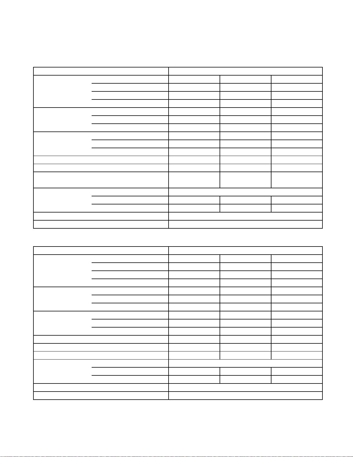
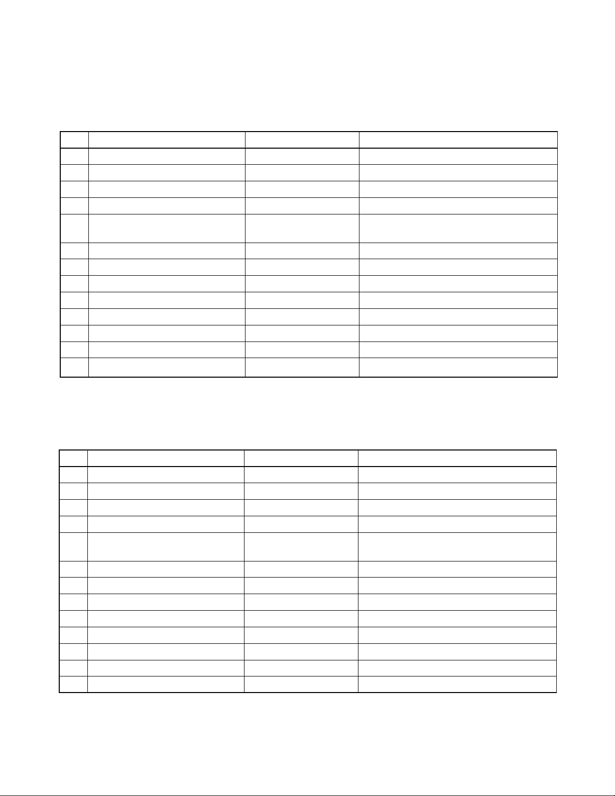
1. SPECIFICATIONS
Specifications
RAS-M10NKV-E, RAS-M13NKV-E, RAS-M16NKV-E
FILE NO. SVM-05019
Power supply
Electric Unit model
characteristice Running current (A)
Power consumption (W)
Power factor (%)
Operating High dB (A)
noise Medium dB (A)
Low dB (A)
Dimension Height (mm)
Width (mm)
Depth (mm)
Net weight (kg)
Fan motor output (W)
Air flow rate
(Cooling/Heating)
Piping Type
connection Liquid side
Gas side
Refrigerant
Wiring connection (Interconnection)
(m3/h) 570/610 590/620 650/660
220/230/240V, 1Ph, 50/60Hz
RAS-M10NKV-E RAS-M13NKV-E RAS-M16NKV-E
0.15 0.15 0.15
303030
87 87 87
36/39
33/35
28/29
275 275275
790
218
10
20
∅6.35
∅9.52
4 wires : includes earth
39/40
35/35
28/29
Flare connection
∅6.35
∅9.52
R410A
790
218
10
20
42/42
39/39
33/33
790
218
10
30
∅6.35
∅12.7
RAS-M10NKCV-E, RAS-M13NKCV-E, RAS-M16NKCV-E
Power supply
Electric Unit model
characteristice Running current (A)
Power consumption (W)
Power factor (%)
Operating High dB (A)
noise Medium dB (A)
Low dB (A)
Dimension Height (mm)
Width (mm)
Depth (mm)
Net weight (kg)
Fan motor output (W)
Air flow rate (m3/h)
Piping Type
connection Liquid side
Gas side
Refrigerant
Wiring connection (Interconnection)
220/230/240V, 1Ph, 50/60Hz
RAS-M10NKCV-E RAS-M13NKCV-E RAS-M16NKCV-E
0.15 0.15 0.15
30 30 30
87 87 87
36 39 42
33 35 39
28 28 33
275 275 275
790 790 790
218 218 218
10 10 10
20 20 30
570 590 650
Flare connection
∅6.35
∅9.52 ∅9.52 ∅12.7
4 wires : includes earth
∅6.35 ∅6.35
R410A
• The specifications may be subject to change without notice for purpose of improvement.
– 2 –
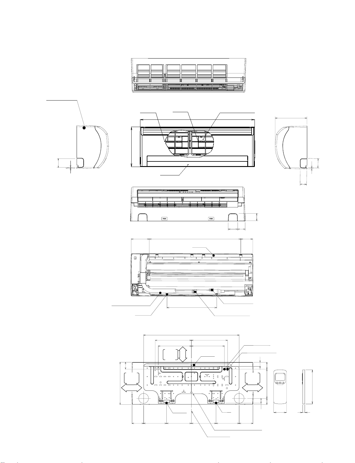
Indoor Unit
FILE NO. SVM-05019
2. CONSTRUCTION VIEWS
Front panel
60
6
Knock out system
Air inlet
Air filter
Heat exchanger
790
275
Air outlet
64
120 80
590
Hanger
218
60
6
48
Knock out system
48
53
Drain hose (0.54m)
Hanger
45
Minimum
distance
to ceiling
275
170 or more
320
620
235 235
215 215
Minimum
distance
to ceiling
65 or more
Hanger
– 3 –
Connecting pipe (0.43m)
(Flare ∅6.35)
Connecting pipe (0.33m)
(For 10,13 series ; Flare ∅9.52
For 16 series ; Flare ∅12.7)
Hanger
For stud bolt (∅6)
Hanger
150150 160160
Installation plate outline
Center line
For stud bolt
(∅8~∅10)
26
Minimum
distance
to ceiling
170 or more
32
9090
4519040
160
57 18
Wireless remote control
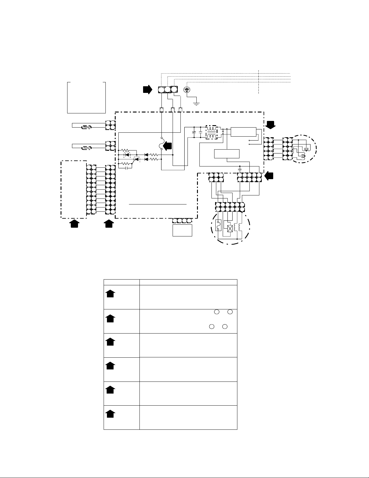
3-1. Indoor Unit (For 10k & 13k)
COLOR INDICATION
:
BROWN
BRW
:
RED
RED
:
WHITE
WHI
:
YELLOW
YEL
:
BLUE
BLU
:
BLACK
BLK
:
GRAY
GRY
:
PINK
PNK
:
ORANGE
ORN
:
GREEN & YELLOW
GRN&YEL
:
GREEN
GRN
BLK
BLK
HEAT EXCHANGER
SENSOR
(TC)
THERMO SENSOR
RECEIVING AND
INFRARED RAYS
MCC-861
MCC-861
(TA)
INDICATING PARTS
CN25
(WH I)
1
2
3
4
5
6
7
8
9
10
11
BLK
BLK
BLU
1
BLU
2
BLU
3
BLU
4
BLU
5
BLU
6
BLU
7
BLU
8
BLU
9
BLU
10
WHI
11
1
CN01
(BLU)
1
2
CN03
(WHI)
1
2
CN13
(WHI)
1
2
3
4
5
6
7
8
9
10
11
4
TERMINAL
1
2
1
2
1
2
3
4
5
6
7
8
9
10
11
BLOCK
MAIN P.C. BOARD
3. WIRING DIAGRAM
3
2
1
2
BLK WHI RED
CN23
CN24
FUSE
F01
T3.15A
250VAC
WP-004
CN21
LINE
FILTER
R04
3
CN11 CN10
1
1
YEL
CN08
3
4
1
2
HA
JEM-A
Drive ci rcuit
2
3
3
2
GRY
1
1
150°C
Fan Motor
BRW
2
3
2
3
supply circ uit
+12 VDC
+5 VDC
4
5
4
5
INDOOR
UNIT
Power
3
5
3
5
BLK
WHI
6
6
FILE NO. SVM-05019
OUTDOOR
UNIT
5
CN07
(WH I)
WHI
1
2
3
4
5
1
1
RED
AC FAN MOTOR
1
1
YEL
2
2
YEL
3
3
YEL
4
4
YEL
5
5
LOUVER MOTOR
6
1
2
3
4
5
Simple Check for Failure Diagnosis
Chec k It em
Check to see if the OPERATION indicator goes on
OPERAT ION
1
INDICATOR
TERMINAL
2
3
4
5
6
(AC 220~24 0V)
and off when t he main s witch or b reaker is turned on.
(Check the primary and secondary voltage of the
transformer.)
Check the power supply voltage b etween and .
(Refer to the name plate.)
(Check the primary and secondary voltage of the
transformer.)
BLOCK
Check the fluctuating voltage between and .
(15~60VDC)
FUSE
Check to see if the fuse blows out.
3.15A
(Check the R04 of the varis tor.)
Check the voltage at the No.4 pin on CN13 connector
of the infr ared receiver.
DC5V
(Check the transform er and the pow er supply ci rcuit
of the rated voltage.)
Check the voltage at the white lead of the louver
motor.
DC12V
(Check the transform er and the pow er supply ci rcuit
of the rated voltage.)
Check the voltage at the No.1 pin on CN10
connecto r and CN24.
(Check the F01)
Refer to the service data for the detailed failure
diagnosis.
Diagnosis Result
1
2
2
3
– 4 –
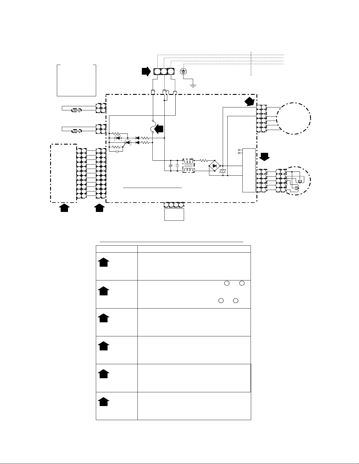
3-2. Indoor Unit (For 16k)
COLOR INDICATION
:
BROWN
BRW
:
RED
RED
:
WHITE
WHI
:
YELL OW
YEL
:
BLUE
BLU
:
BLACK
BLK
:
GRAY
GRY
:
PINK
PNK
:
ORANGE
ORN
:
GREEN & YE LLOW
GRN&YEL
:
GREEN
GRN
HEAT EXCHANGER
SENSOR
(TC)
THERMO SENSOR
(TA)
CN25
(WHI)
1
2
3
4
5
6
7
8
9
RECEIVING AND
INFRARED RAYS
INDICATING PARTS
10
MCC-861
MCC-861
11
1
CN01
(BLU)
BLK
1
1
BLK
2
2
CN03
(WHI)
BLK
1
1
BLK
2
2
CN13
(WHI)
BLU
1
1
1
BLU
2
3
4
5
6
7
8
9
10
11
BLU
BLU
BLU
BLU
BLU
BLU
BLU
BLU
WHI
2
2
3
3
4
4
5
5
6
6
7
7
8
8
9
9
10
10
11
11
4
TERMINAL
BLOCK
FUSE
F01
T3.15A
250VAC
2
CN24
BLK
1
WHI
CN23
3
2
MAIN P.C. BOARD
MCC-867or MCC-5014
1
3
RED
R04
CN08
3
2
HA
JEM-A
CN21
FILTER
4
LINE
R05
DB01
~
-+
~
C03
+
INDOOR
UNIT
DC5V
DC12V
FILE NO. SVM-05019
OUTDOOR
UNIT
CN10
6
(WHI)
1
3
4
5
6
CN07
(WHI)
1
2
CIRCUIT
3
4
POWER SUPPLY
5
FAN MOTOR
RED
1
BLK
3
4
5
6
WHI
YEL
BLU
DC MOTOR
5
WHI
1
1
2
3
4
5
1
YEL
2
2
YEL
3
3
YEL
4
4
YEL
5
5
LOUVER MOTOR
Simple Check for Failure Diagnosis
Check Item
OPERATION
1
INDICATOR
TERMINAL
2
BLOCK
3
4
5
6
(DC310 340V)
DC12V
DC325V
~
Check to see if the OPERATION indicator goes on
and off when the main switch or breaker is turned on.
(Check the primary and secondary voltage of the
transformer.)
Check the power supply voltage between 1 and
(Refer to the name plate.)
(Check the primary and secondary voltage of the
transformer.)
Check the fluctuating voltage between and .
(15
60VDC)
~
Check to see if the fuse blows out.
FUSE
(Check the R04 of the varistor.)
3.15A
Check the voltage at the No.4 pin on CN13 connector
of the infrared receiver.
DC5V
(Check the transformer and the power supply circuit
of the rated voltage.)
Check the voltage at the white lead of the louver
motor.
(Check the transformer and the power supply circuit
of the rated voltage.)
Check the voltage at the No.1 pin on CN10
connector.
(Check the DB01, R05 and C03.)
Refer to the service data for the detailed failure
diagnosis.
Diagnosis Result
2
2
.
3
– 5 –
FILE NO. SVM-05019
4. SPECIFICATIONS OF ELECTRICAL PARTS
RAS-M10NKV-E, RAS-M13NKV-E
RAS-M10NKCV-E, RAS-M13NKCV-E
No. Parts name Type Specifications
1 Fan motor (for indoor) SKF-220-20-4A-1 AC Motor with 150°C thermo fuse
2 Thermo. sensor (TA-sensor) ——— 10 kΩ at 25°C
3 AC-AC transformer (T01) TT-10 187 − 276V, 6VA
4 Microcomputer
5 Heat exchanger sensor
(TC-sensor)
6 Line filter (L01) SS11V-06270 27 µH , AC 0.64A
7 Diode (DB01) KBP06M 1.5A, 420V
8 Capacitor (C50)
9 Fuse (F01) BET 3.15A 250VAC T3.15A, 250 V
10 Regulator IC (IC08) NJM7812 12VDC, 1.5A max
11 Regulator IC (IC11) NJM7805 5VDC, 1.5A max
12 Varistor (R21, R109) 15G561K 560 V
µPD780024AGK
——— 10 kΩ at 25°C
LXV35VB2200MJ20 2200 µF, 35V
13 Louver motor 24BYJ48 DC 12V
RAS-M16NKV-E, RAS-M16NKCV-E
No. Parts name Type Specifications
1 Fan motor (for indoor) ICF-340-30-2 DC 340 V, 30 W
2 Thermo. sensor (TA-sensor) ——— 10 kΩ at 25°C
3 DC-DC transformer (T01) SWT-70 DC 390 V, Secondary DC 15 V, 12 V, 7 V
4 Microcomputer µPD780024AGK
5 Heat exchanger sensor
(TC-sensor)
6 Line filter (L01) SS11V-06270 27mH, AC 0.6A
7 Diode (DB01) D3SBA60 4A, 600 V
8 Capacitor (C03) KMH450VSSN120M25C 120µF, 450 V
9 Fuse (F01) FCU250V, 3.15A T3.15A, 250 V
10 Power supply IC (IC01) STR-L472
11 Varistor (R21, R109) 15G561K 560 V
——— 10 kΩ at 25°C
12 Resistor (R01) RF-5TK4R7 4.7Ω, 5 W
13 Louver motor 24BYJ48 12VDC
– 6 –

5. CONTROL BLOCK DIAGRAM
FILE NO. SVM-05019
5-1. Indoor Unit
Heat Exchanger Sensor
Temperature Sensor
Infrared Rays Signal Receiver
Infrared
Rays
Remote
Control
Initiallizing Circuit
Clock Frequency
Oscillator Circuit
Power Supply
Circuit
Noise Filter
Indoor Unit Control Panel
M.C.U.
Functions
• Louver Control
• 3-minute Delay at Restart for Compressor
• Motor Revolution Control
• Processing
(Temperature Processing)
• Timer
Outdoor unit
ON/OFF Signal
Louver ON/OFF Signal
Louver Driver
Operation
Display
Timer
Display
Filter Sign
Display
Fan Only
Sign Display
Indoor Fan
Motor
Louver Motor
From Outdoor Unit
REMOTE CONTROLLER
RAS-M10NKV-E, RAS-M13N
(Heat pump model)
Remote Controller
Operation ( )
Operation Mode Selection
AUTO, COOL, DRY, HEAT
Thermo. Setting
Fan Speed Selection
ON TIMER Setting
OFF TIMER Setting
Louver AUTO Swing
Louver Direction Setting
KV-E, RAS-M16NKV-E
Infrared
Rays
Outdoor Unit
RAS-M10NKCV-E, RAS-M13N
(Cooling only model)
Remote Controller
Operation ( )
Operation Mode Selection
AUTO, COOL, DRY, FAN ONLY
Thermo. Setting
Fan Speed Selection
ON TIMER Setting
OFF TIMER Setting
Louver AUTO Swing
Louver Direction Setting
KCV-E, RAS-M16NKCV-E
Infrared
Rays
ECONO.
ECONO.
– 7 –

6. OPERATION DESCRIPTION
FILE NO. SVM-05019
6-1. Outline of Air Conditioner Control
This air conditioner is a capacity-variable type air
conditioner. The capacity proportional control
compressor which can change the motor speed is
mounted. The indoor unit motor drive circuit is
mounted to the indoor unit. The compressor and the
inverter to control outdoor unit motor are mounted to
the outdoor unit. The entire air conditioner is mainly
controlled by the indoor unit controller.
The indoor unit controller drives the indoor fan motor
based upon command sent from the remote controller, and transfers the operation command to the
outdoor unit controller.
The outdoor unit controller receives operation
command from the indoor unit side, and controls the
outdoor fan and the pulse modulating valve.
Besides, detecting revolution position of the compressor motor, the outdoor unit controller controls
speed of the compressor motor by controlling output
voltage of the inverter and switching timing of the
supply power (current transfer timing) so that motors
drive according to the operation command.
And then, the outdoor unit controller transfers
reversely the operating status information of the
outdoor unit to control the indoor unit controller.
As the compressor adopts four-pole
brushless DC motor, the frequency of the
supply power from inverter to compressor
is two-times cycles of the actual number of
revolution.
(1) Role of indoor unit controller
The indoor unit controller judges the operation
commands from the remote controller and
assumes the following functions.
• Judgment of suction air temperature of the
indoor heat exchanger by using the indoor
temp. sensor.
• Temperature setting of the indoor heat ex-
changer by using heat exchanger sensor
(Prevent-freezing control)
• Louver motor control
• Indoor fan motor operation control
• LED display control
• Transferring of operation command signal
(Serial signal) to the outdoor unit
• Reception of information of operation status
(Serial signal including outside temp. data) to
the outdoor unit and judgment/display of error
(2) Role of outdoor unit controller
Receiving the operation command signal (Serial
signal) from the indoor controller, the outdoor
unit performs its role.
• Compressor operation
control
• Operation control of
outdoor fan motor
•
P.M.V. control
• Detection of inverter input current and current
release operation
• Over-current detection and prevention opera-
tion to transistor module (Compressor stop
function)
• Compressor and outdoor fan stop function
when serial signal is off (when the serial signal
does not reach the board assembly of outdoor
control by trouble of the signal system)
• Transferring of operation information (Serial
signal) from outdoor unit to indoor unit
• Detection of outdoor temperature and opera-
tion revolution control
• Defrost control in heating operation (Temp.
measurement by outdoor heat exchanger and
control for 4-way valve and outdoor fan)
(3) Contents of operation command signal (Serial
signal) from indoor unit controller to outdoor unit
controller
The following three types of signals are sent
from the indoor unit controller.
• Operation mode set on the remote controller
• Compressor revolution command signal
defined by indoor temperature and set temperature
(Correction along with variation of room
temperature and correction of indoor heat
exchanger temperature are added.)
• For these two types of signals ( [Operation
mode] and [Compressor revolution] ), the
outdoor unit controller monitors the input
current to the inverter, and performs the
followed operation within the range that current
does not exceed the allowable value.
• Temperature of indoor heat exchanger by
indoor heat exchanger sensor
(Minimum revolution control)
Operations followed
to judgment of
serial signal from
indoor side.
− 8 −
FILE NO. SVM-05019
(4) Contents of operation command signal (Serial
signal) from outdoor unit controller to indoor unit
controller
The following signals are sent from the outdoor
unit controller.
• The current operation mode
• The current compressor revolution
• Outdoor temperature
• Existence of protective circuit operation
For transferring of these signals, the indoor unit
controller monitors the contents of signals, and
judges existence of trouble occurrence.
Contents of judgment are described below.
• Whether distinction of the current operation
status meets to the operation command
signal
• Whether protective circuit operates
When no signal is received from the outdoor
unit controller, it is assumed as a trouble.
6-1-1. Capacity Control
The cooling capacity is varied by changing compressor motor speed. The inverter changes compressor
motor speed by changing AC 220–240V power to
DC once, and controls capacity by changing supply
power status to the compressor with transis-tor
module (includes 6 transistors). The outline of the
control is as follows : The revolution position and
revolution speed of the motor are detected by
detecting winding electromotive force of the com
pressor motor under operation, and the revolution
speed is changed so that the motor drives based
upon revolution speed of the operation command by
changing timing (current transfer timing) to ex
change inverter output voltage and supply power
winding.
Detection of the revolution position for controlling is
performed 12 times per 1 revolution of compressor.
The range of supply power frequency to the com
pressor differs according to the operation status
(COOL, DRY).
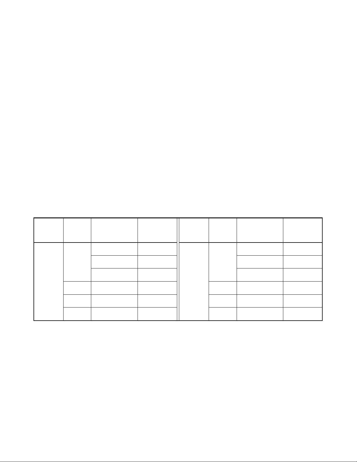
Table 6-1-1 Compressor revolution range
Operation
mode
COOL
No. of
operating
unit
1 unit
2 units
3 units
4 units
Combination
of indoor units
M10
M13
M16
*
*
*
Compressor
revolution
(rps)
20 to 28
20 to 43
20 to 53
20 to 66
31 to 69
31 to 69
* In case that any multiple indoor units are combined.
6-1-2. Current Release Control
The outdoor main circuit control section (Inverter
assembly) detects the input current to the outdoor
unit. If the current value with compressor motor
speed instructed from indoor side exceeds the
specified value, the outdoor main circuit control
section controls compressor motor speed by reducing motor speed so that value becomes closest to
the command within the limited value.
Operation
mode
HEAT
No. of
operating
unit
1 unit
2 units
3 units
4 units
Combination
of indoor units
M10
M13
M16
*
*
*
Compressor
revolution
(rps)
15 to 52
15 to 63
15 to 67
15 to 90
17 to 90
22 to 90
6-1-3. Power Factor Improvement Control
Power factor improvement control is performed
mainly aiming to reduce the current on much power
consumption of cooling/heating operation. Controlling starts from the time when input power has
reached at a certain point. To be concrete, IGBT of
the power factor improvement circuit is used, and the
power factor is improved by keeping IGBT on for an
arbitrary period to widen electro-angle of the input
current.
− 9 −
FILE NO. SVM-05019
6-1-4. Prevent-Freezing Control
The indoor heat exchanger sensor detects refrigerant vapor temperature in COOL/DRY operation. If
the temperature is below the specified value, compressor motor speed is reduced so that operation is
performed in temperature below the specified value
to prevent-freezing of indoor heat exchanger.
6-1-5. P. M. V. (Pulse Modulating Valve)
Using P.M.V., refrigerant flow of refrigeration cycle is
varied for the optimum temperature. Controlling
each unit separately by four P.M.V. corresponds to
difference of pipe length, fan speed, and unit temperature.
If an error occurs on cycle temperature when power
source of the air conditioner has been turned on,
and if start/stop times of the outdoor unit are 30
times, move the valve once until it hits on the stopper
for positioning of the valve. In this case, ticktack
sound may be heard.
6-1-6. Louver Control
(1) Vertical air flow louvers
Positions of vertical air flow louvers are automatically controlled according to the operation status
(AUTO, COOL, DRY, HEAT). Besides, positions of
vertical air flow louvers can be arbitrarily set by
pressing the [FIX] button. The louver position which
has been set by the [FIX] button is stored in microcomputer, and the louver is automatically set at the
stored position in the next operation.
(2) Swing
If the [SWING] button is pressed during running
operation, vertical air flow louvers start swinging.
When the [SWING] button is pressed again, swinging
stops.
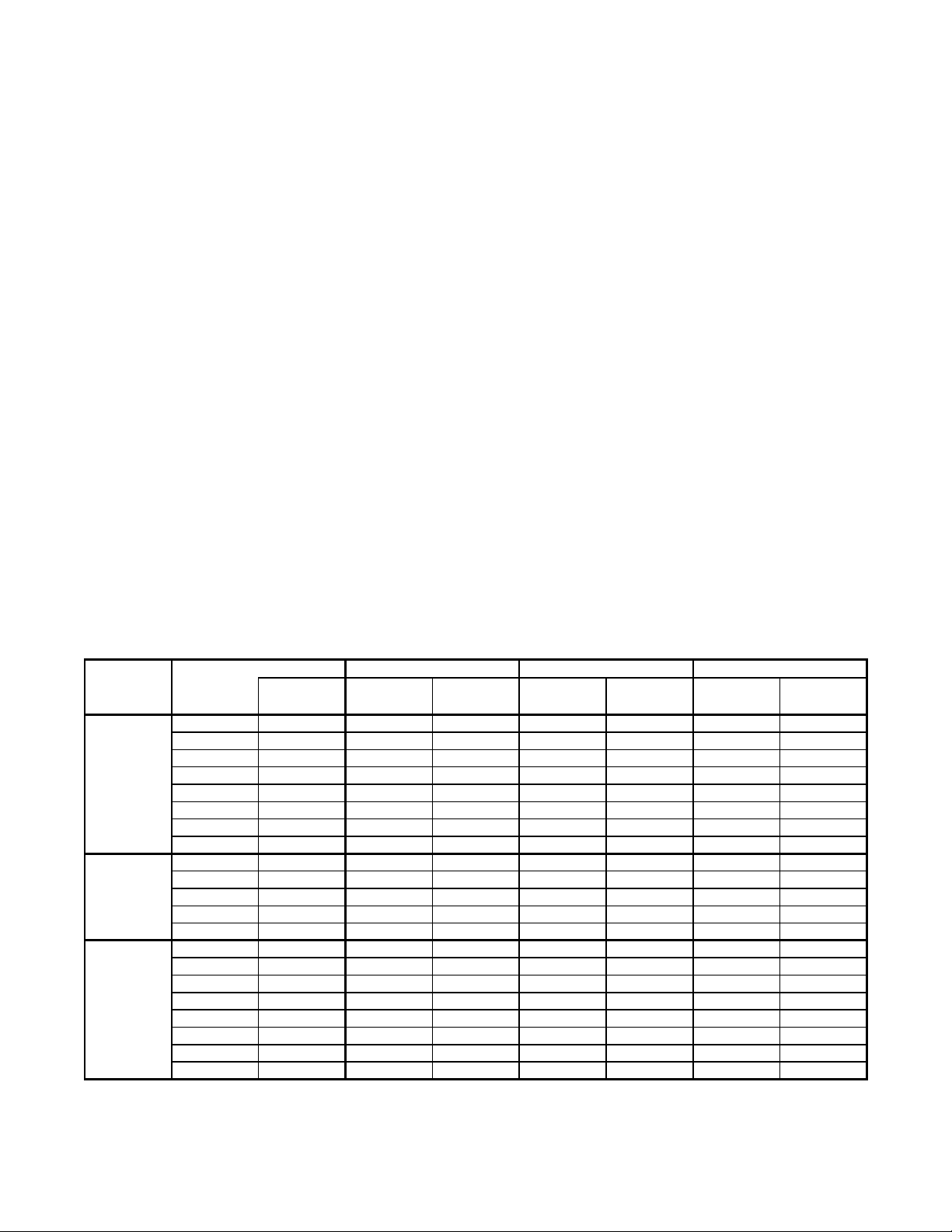
6-1-7. Indoor Fan Control
The indoor fan is operated by motor speed non-step
variable drive system motor. For flow rate, motor
speed is controlled manually in five steps and with
the unit of 10 rpm from upper limit to lower limit in
AUTO mode as described in Table 6-1-2. It is not
selected by relay, so selecting sound does not
generate.
operation
mode
Cooling
and Fan
only
DRY
Heating
Table 6-1-2
Fan
mode
H
M+
M
L+
L
LL+
L
L-
UL
SUL
H
M+
M
L+
L
L-
Remote
Control
HIGH
MED+
MED
LOW+
LOW
HIGH
MED+
MED
LOW+
LOW
Motor speed
(rpm)
M10
Air flow rate
(m3/h)
1190
1120
1120
1050
980
930
910
850
930
910
850
720
660
1250
1200
1160
1060
1000
1050
940
930
570
530
530
490
440
420
410
370
420
410
370
290
260
610
570
550
490
460
490
420
420
Motor speed
(rpm)
1210
1130
1130
1050
M13
Air flow rate
980
930
910
850
930
910
850
750
700
1290
1280
1200
1100
1020
1050
940
930 420
(m3/h)
590
530
530
490
440
420
410
370
420
410
370
310
280
620
620
570
520
470
490
420
M16
Motor speed
(rpm)
Air flow rate
1350
1250
1250
1150
1070
1000
980
920 410
1000
980
920
920
800
1370
1360
1280
1180
1100
1150
1020
1000 460
(m3/h)
650
610
610
550
500
460
440
460
440
410
410
340
660
660
620
560
520
550
470
NOTE :
• UL : Ultra Low, SUL : Super Ultra Low
− 10 −
FILE NO. SVM-05019
6-1-7. Outdoor Fan Control (DC Fan Motor)
Although the outdoor fan motor drives the outdoor fan by non-step variable system of the revolution speed, the
revolution speed is restricted to three steps on the convenience of controlling.
If a strong wind is lashing outside of the room, the operation may be continued as the outdoor fan stops in order
to protect the outdoor fan motor.
If a fan lock occurred due to entering of foreign matter, the air conditioner stops and an alarm is displayed.
<COOL, DRY>
Table 6-1-3
Compressor revolution (rps)
Outdoor temp.
sensor
TO
ECONO.
operation
TO ≥ 38°C
TO < 38°C
TO ≥ 38°C
TO < 38°C
TO is abnormal
1 to 2 units
3 to 4 units
20.3
390 (rpm) 700 (rpm) 700 (rpm) 700 (rpm)
390 (rpm) 640 (rpm) 640 (rpm) 700 (rpm)
390 (rpm) 500 (rpm) 640 (rpm) 700 (rpm)
390 (rpm) 640 (rpm) 640 (rpm) 640 (rpm)
390 (rpm) 500 (rpm) 500 (rpm) 500 (rpm)
500 (rpm) 640 (rpm) 640 (rpm) 640 (rpm)
~ 50.3 ~ 62.8 63.4 ~
<HEAT>
Table 6-1-4
Compressor revolution (rps)
Outdoor temp. sensor TO ≥ 5°C
TO TO < 5°C
ECONO. operation
TO ≥ 5°C
TO < 5°C
TO is abnormal
20.3 ~ 33.3 ~ 33.9
390 (rpm) 640 (rpm) 640 (rpm)
500 (rpm) 640 (rpm) 640 (rpm)
390 (rpm) 500 (rpm) 500 (rpm)
390 (rpm) 500 (rpm) 500 (rpm)
390 (rpm) 500 (rpm) 640 (rpm)
6-2. Description of Operation Circuit
• Turning [ON] the breaker flashes the operation lamp.
This is the display of power-ON (or notification of po wer failure).
• When pushing [ ] button of the remote controller, receive sound is issued from the main unit, and
the next operations are performed together with opening the vertical air flow louvers.
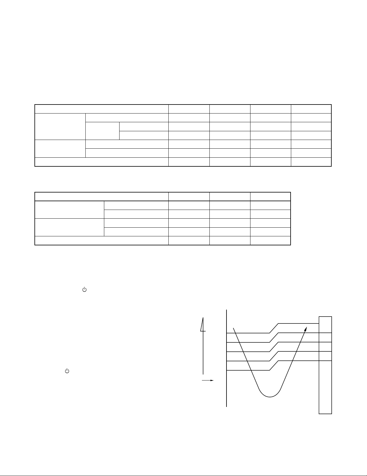
6-2-1. Fan Only Operation
(The Remote controller [MODE] Button
is Set to the FAN ONLY Operation)
• This mode is only for the cooling only model.
• Once the setting is made, the operation mode is
memorized in the microcomputer so that the same
operation can be effected thereafter simply by
pushing [ ] button.
• When the [FAN] button is set to the AUTO position,
the indoor fan motor operates as shown in Fig. 62-1. When the [FAN] button is set to LOW, LOW
MED, MED+, or HIGH, the motor operates with a
constant air flow.
• ECONO, Hi POWER and COMFORT SLEEP
mode cannot be set.
+
− 11 −
˚C
+3
+2.5
+2
+1.5
+1
+0.5
(Room temp.) – (Set temp.)
Set
temp.
0
(Set temp.) 25˚C
NOTE :
1: Calculated from difference in motor speed of M+
*
and L–, and controlled.
Fig. 6-2-1 Auto setting of air flow
M+
*1
*1
*1
L–
FILE NO. SVM-05019
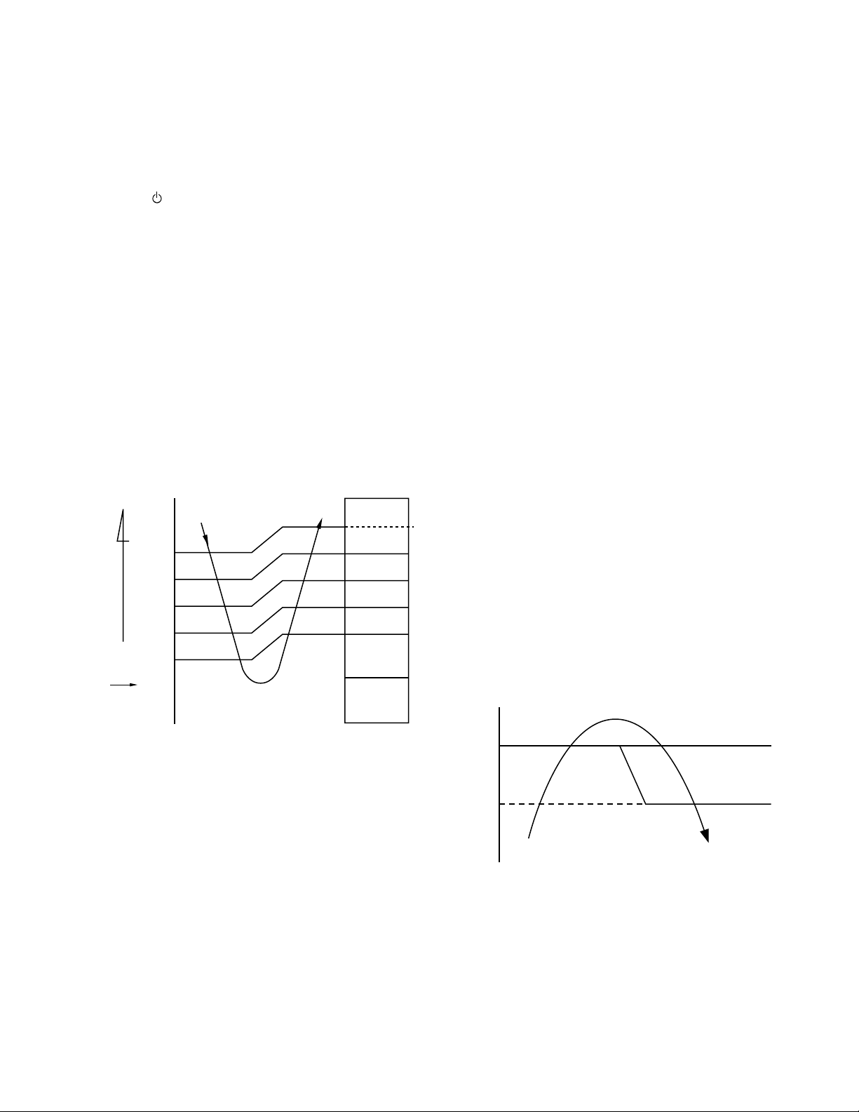
6-2-2. Cooling Operation
(The Remote controller [MODE] Button
is Set to the COOL Position)
• Once the setting is made, the operation mode is
memorized in the microcomputer so that the same
operation can be effected thereafter simply by
pushing [ ] button.
• A cooling operation signal is transmitted to outdoor
unit.
• The indoor fan motor operates as shown in Fig.62-2 when [FAN] button is set to AUTO.
• The motor operates with a constant air flow when
the [FAN] button is set to LOW, LOW+, MED, MED+,
or HIGH.
• The outdoor unit controls the outdoor fan relay
R01, R02 and R03, and the compressor motor
speed according to the operation command signal
sent from the indoor unit.
˚C
+3
+2.5
+2
+1.5
+1
(Room temp.) – (Set temp.)
+0.5
Set
temp.
0
–0,5
NOTE :
1: Calculated from difference in motor speed of M+
*
and L–, and controlled.
Fig. 6-2-2 Setting of air flow [Air Flow AUTO]
M+
*1
*1
*1
L–
In normal
operation
(1) Cooling capacity control
• The cooling capacity and room temperature
are controlled by changing the compressor
motor speed according to both the difference
between the temperature detected by the room
temperature sensor and the temperature set by
[TEMP] button and also any change in room
temperature.
• When compressor has been activated or
reactivated, it operates with Max. 33 rps for 2
minutes and with Max. 57 rps from 2 to 4
minutes passed.
• When room temperature is lower than set
temperature and indoor fan motor is operated
at fan speed L– as shown in Fig. 6-2-2 while
the outdoor unit stops.
(2) Prevent-freezing control
If temperature of indoor heat exchanger detected
by the indoor heat exchanger sensor is 5°C or
lower, compressor motor speed is gradually
lowered to pre vent freezing of the indoor heat
exchanger. If temperature is 7°C or higher, return
the operation to the above item (1).
(3) Current release control
The input current of compressor and outdoor fan
motor (Precisely inverter main circuit control
section) which occupy most of air conditioner
input is detected by the outdoor current sensor ,
and compressor motor speed is gradually lowered
so that current value does not exceed 11.5A if
current value exceeds 11.5A. When the current
value lowers to 11.0A, return the operation to the
above item (1).
Comp. motor
14.2
13.7
Current value
Normal control
speed down
Comp. motor
speed keep
Fig. 6-2-3
(4) Outdoor temperature release control
The outdoor temperature release is controlled by
changing the current release points 14.2 and 13.7
in the above item according to temperature
detected by the outdoor temperature sensor.
For example, if the outdoor temperature is 43°C,
the value of current release points becomes 9.6A.
− 12 −
FILE NO. SVM-05019
(5) Limit for maximum compressor motor speed
by indoor fan speed
When outdoor temperature sensor detected
32°C or lower, and indoor heat exchanger
sensor detected 17°C or lower, the maximum
compressor motor speed is limited by the indoor
fan speed.
For example, when 1 unit only operates, the
compressor motor speed is limited as described
in the table below.
Table 6-2-1
Air flow
rate
HIGH
M+
MED
L
L–
UL
SUL
M10 M13 M16
(rps) (rps) (rps)
32 48 54
29 42 46
24 28 38
20 20 30
20 20 30
20 20 20
20 20 20
(6) Louver control
The vertical air flow louvers are automatically set
to horizontal or cool memory position.
When temperature of indoor heat exchanger
becomes 5°C or lower by the prevent-freezing
control and the compressor is turned off, the
vertical air flow louvers close once and then
return to the position of previous time.
(7) Discharge temperature control
The discharge temperature of refrigerant gas
from the compressor is detected by the discharge temperature sensor, and controls operating compressor motor speed.
1) Control 1 (A zone) : Normal operation zone
When TD detect value is 101°C or lower, the
operation is performed with operating motor
speed instructed by the serial signal.
2) Control 2 (B zone) : Slow-up zone of motor
speed
When TD detect value is 101°C or higher,
operating motor speed is slowly up.
3) Control 3 (C zone) : Keep zone
When TD detect value is 108°C or higher,
operating motor speed is not changed if
raising operation speed.
4) Control 4 (D zone) : Slow down zone of motor
speed
When TD detect value is 111°C or higher,
operating motor speed is slowly down.
5) Control 5 (E zone) : Normal down of motor
speed
When TD detect value is 115°C or higher,
operating motor speed is down.
6) Control 6 (F zone) : Operation stop zone
If TD detect value exceeds 120°C during
operation, stop the operation immediately.
Then, restart the operation when TD detect
value becomes 108°C or lower.
TD
(˚C)
120
115
111
108
101
Zone
F
E
D
C
B
A
Operation stop zone
Normal down zone of motor speed
Slow down of motor speed
Keep zone : Motor speed is not changed.
Slow-up zone of motor speed
Normal operation zone
Fig. 6-2-4 Compressor motor speed control
– 13 –
Release of motor speed
FILE NO. SVM-05019
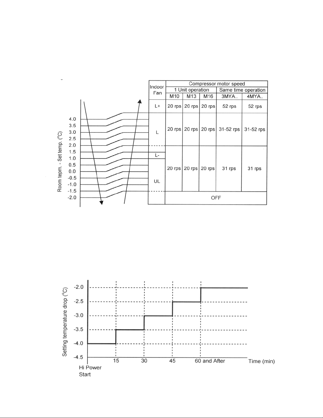
(8) ECONO operation control
When the [ECO] button is pushed, ECONO
operation is performed by restraining air flow
and compressor motor speed. The set
temperature is changed also.
1) The set temperature increased 0.5°C per hour up
to 2°C starting from the set temperature when
ECONO has been received.
2) Indoor air flow is controlled between L+ and UL.
The compressor motor speed in control as shown
in Fig. 6-2-5
(9) COMFORT SLEET operation control.
When the [COMFORT SLEEP] button is
pushed, the ECONO operation activate
together with the timer OFF function. Each
time of pressing [COMFORT SLEEP] button
the off timer setting changes in the sequence
of 1, 3, 5 or 9 hours.
Fig. 6-2-5
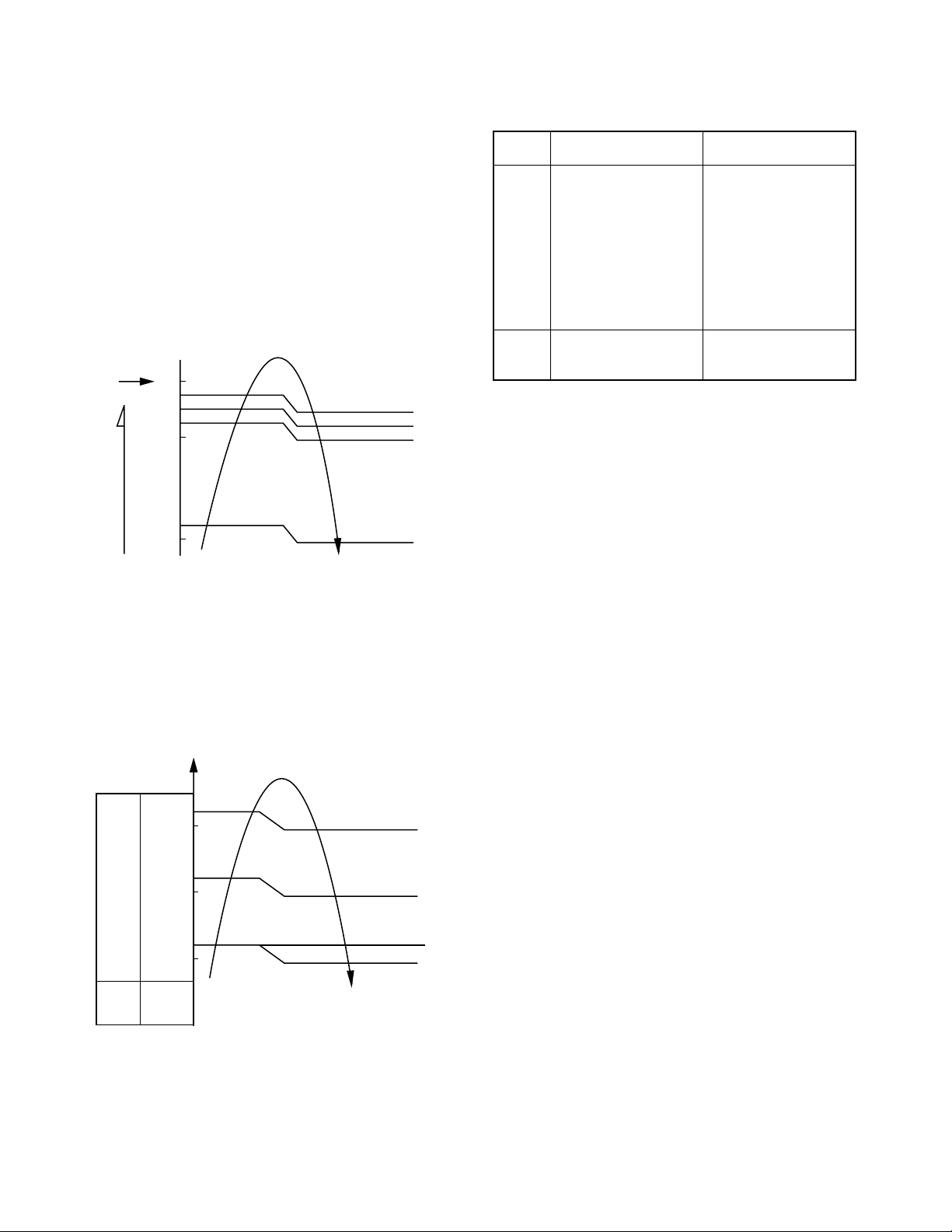
(10) Hi POWER operation control.
When the [Hi POWER] button is pushed
Hi Power operation is performed by change
set temperature and air flow (display on the
remote control does not change).
1) Changing of set temperature.
Fig. 6-2-6
− 14 −

FILE NO. SVM-05019
–0.5
0
+0.5
+1.0
+1.5
+2.0
+2.5
*1
L–
SUL
(Room temp.) – (Set temp.)
Set
temp.
2) Changing of air flow (Fan setting : AUTO)
When the Hi POWER is started, the fan of the
indoor unit operates at higher air flow level than
normal air flow AUTO (normal air flow AUTO
is shown in Fig. 6-2-2). Because of the
difference between room temperature and set
temperature are increased automatically.
3) Changing of air flow (Fan setting : One of 5
levels)
When the Hi POWER is started, the fan of the
indoor unit operates at higher consecutive air
flow level. (Fan speed on the display of remote
control does not change)
4) Changing of louver position
If the room temperature is higher than setting
temperature by 3.5 °C or more, the louver is
automatically set to the maximum air flow
position. If it is not, position of louver is not
change. When room temperature is reach to
setting temperature. The louver moves back
to set position.
(11) Quiet operation control.
When the [QUIET] button is pushed, the fan is
restricted the revolution speed at L- level until
the [QUIET] button is pushed once again
(cancel QUIET operation).
Remarks :
QUIET operation is appropriate to work with
less cooling load condition. Because of the
fan speed L- may cause not enough the
cooling capacity.
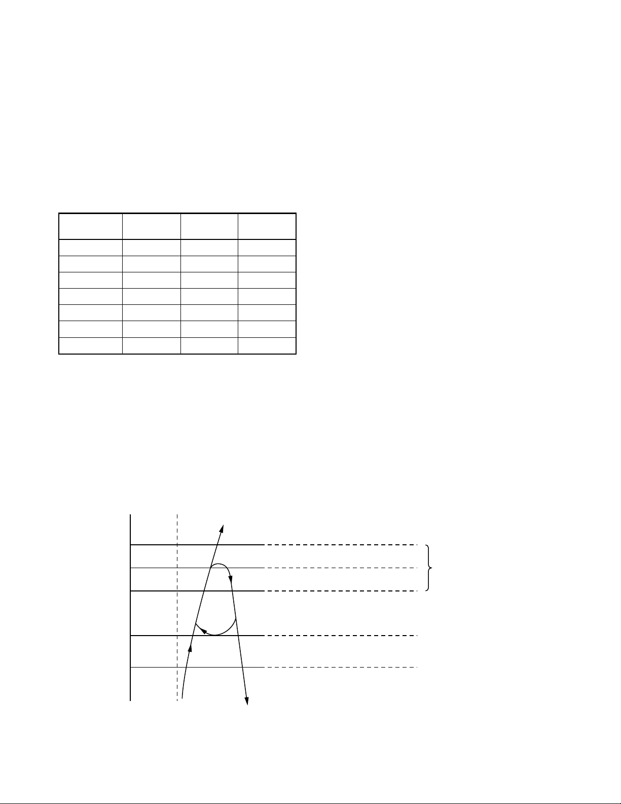
6-2-3. DRY Operation
(The Remote controller [MODE] Button
is Set to the DRY Position)
• Once the setting is made, the operation mode is
memorized in the microcomputer so that the same
operation can be effected thereafter simply by
pushing [ ] button.
• Dry operation signal is transmitted to outdoor unit.
• The Cooling operation giving priority to dehumidi-
fying, which restrains the indoor fan speed and
compressor motor speed, is performed.
• The indoor fan motor operates as shown in Fig.
6-2-7. (Fan speed is AUTO only.)
• The outdoor unit controls the outdoor fan relay
R01, R02 and R03, and the compressor motor
speed according to the operation command signal
sent from the indoor unit.
NOTE :
1 : Middle motor speed between L– and SUL
*
Fig. 6-2-7 Setting of air flow
(1) Dehumidifying-preferential Cooling capacity
control
• The cooling capacity and room temperature are
controlled by changing the compressor motor
speed according to both the difference between
the temperature detected by the room temperature
sensor and the temperature set by [TEMP] button
and also any change in room temperature.
• When the air conditioner operates in Dry mode, the
maximum compressor motor speed is restricted.
M10 : Max. 20 rps
M13 : Max. 20 rps
M16 : Max. 22 rps
While multiple indoor units operate, compressor
motor speed is calculated in the outdoor unit to
operate.
• When room temperature is lower than set tempera-
ture, indoor fan motor is operated at fan speed SUL
as shown in Fig. 6-2-6 while the outdoor unit stops.
• ECONO Hi POWER, QUIET and COMFORT-
SLEEP mode cannot be set.
• Other controls than the above-mentioned controls
are common to those of cooling operation.
− 15 −
6-2-4. Heating Operation
33
*
3
*
2
32
44
43
20
19
31
30
A
A
−
8
A + 4
A
−
8
HIGH
SUL
SUL
FAN
AUTO
Starting
of FAN
Manual
Approximate
revolution speed
of HIGH and SUL
linear by Tc.
Stop
( NOTE : *1)
Transferring of heating operation signal from indoor
unit to outdoor unit starts.
The indoor fan motor operates by the room temperature when selecting "AUTO" of "FAN" as shown in
Fig. 6-2-8, and operates with a set air flow when
selecting LOW to HIGH.
However, to prevent cold draft, revolution speed of
the fan is restricted by indoor heat exchanger when
air flow is AUTO (Fig.
6-2-9) and sta
rting of FAN
Manual.
[Basic control]
(3) SUL : Super ultra low
[In star ting and in stability]
In star ting
• Until 12 minutes
passed after
operation start
FAN
AUTO
• When 12 to 25
minutes passed
after operation start
and room temp. is
3°C or lower than
set temp.
FILE NO. SVM-05019
In stability
• When 12 to 25
minutes passed
after operation start
and room temp. is
higher than (set
temp. --3°C)
• When 25 minutes or
more passed after
operation start
Set
temp.
−
(Room temp.)
(Set temp.)
1, *2 : Approximate revolution speed of M+ and L to
*
0
−0.5
−
1
−
1.5
−
2
−
5.0
−
5.5
[FAN AUTO]
LOW
1
*
2
*
M+
HIGH
linear according to temperature.
Fig. 6-2-8 Setting of air flow
[Cold draft preventing control]
The upper limit of fan revolution speed is shown
below.
FAN
Manual
• Room temp.≥
Set temp. − 4°C
• Room temp. >
Set temp. − 3,5°C
The outdoor unit controls the outdoor fan based
upon the operation signal sent from the indoor unit,
and also controls revolution speed of the compressor motor.
The power coupler (IC20) for four-way valve is
turned on, and turned off in defrost operation.
(1) Heating capacity control
Calculate the difference between temperature
detected by room temp. sensor every minute and
the set temp. set on "Temp. indicator" and
variation amount of room temp.
Then, obtain the correction amount of the
command signal, and correct the current frequency command signal.
(2) High-temp. release control
If temperature of the indoor heat exchanger
detected by the indoor heat exchanger sensor is
55°C or higher, compressor motor speed is
gradually lowered to prevent over-temp. rising of
compressed pressure.
If temperature becomes below 48°C, return to
above item (1).
Fig. 6-2-9 Cold draft preventing control
NOTES :
(1) Stops for 2 minutes after thermostat-OFF.
(2) 24°C when the set temp. is 24°C or more
Set temp. when the set temp. is below 24°C
(3) Current release control
The input current of compressor and outdoor fan
motor (Precisely inverter main circuit control
section) which occupy most of air conditioner
input is detected by the outdoor current sensor.
The compressor motor speed is lowered gradually according to the range of TO (outside air
temp.) if the input current exceeds the current
value determined in each zone as shown in Fig.
6-2-10 so that the input current does not exceed
the set value.
In case that the current lowered by approx. 0.3A to
0.5A than each set value, return to above item (1).
− 16 −
Loading...